BLA boost unit - Siebert Hydraulik & Pneumatik
BLA boost unit - Siebert Hydraulik & Pneumatik
BLA boost unit - Siebert Hydraulik & Pneumatik

Create successful ePaper yourself
Turn your PDF publications into a flip-book with our unique Google optimized e-Paper software.
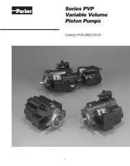
<strong>BLA</strong><br />
<strong>boost</strong> <strong>unit</strong><br />
Catalogue HY17-8224/UK<br />
November 2004
Catalogue HY02-8001/UK<br />
Content<br />
Boost <strong>unit</strong>s<br />
<strong>BLA</strong><br />
Contents Page 10-2-<br />
General information.......................................................... 3<br />
Description....................................................................... 3<br />
Oil cooling........................................................................ 3<br />
Filter................................................................................. 4<br />
Boost <strong>unit</strong> selection.......................................................... 4<br />
Boost pressure................................................................. 5<br />
Installation........................................................................ 5<br />
Line connection ............................................................... 6<br />
Reservoir.......................................................................... 6<br />
Valves............................................................................... 6<br />
Ordering information........................................................ 6<br />
Available versions............................................................. 6<br />
Filter cartridges................................................................ 6<br />
Installation dimensions..................................................... 7<br />
10-2- 2 Parker Hannifin Corporation<br />
Hydraulics Group
Catalogue HY02-8001/UK<br />
General information<br />
The <strong>BLA</strong> <strong>boost</strong> <strong>unit</strong> simplifies the building of closed or<br />
semi-closed hydrostatic transmissions.<br />
Main features are:<br />
• Replaces conventional charge pump and<br />
corresponding valves in many applications<br />
• Allows pump speeds above normal selfpriming<br />
speed.<br />
• Suitable for system flow rates to 400 l/min<br />
• Includes filter<br />
• Simple construction - no moving/wear parts<br />
• Cost-effective installation<br />
• Small tank size<br />
• Helps in building a low-cost hydrostatic<br />
transmission.<br />
Boost <strong>unit</strong>s<br />
<strong>BLA</strong><br />
Typical applications:<br />
• Fan drives<br />
• Propeller drives<br />
• Generator drives<br />
• Pump drives.<br />
Description<br />
In a closed circuit hydrostatic transmission, a charge<br />
pump is normally included with the main pump, providing<br />
make-up fluid which replaces pump and motor<br />
volumetric losses. It also maintains sufficient pump inlet<br />
pressure to avoid cavitation.<br />
The <strong>BLA</strong> <strong>boost</strong> <strong>unit</strong> replaces the charge pump in many<br />
applications, when the following conditions are met:<br />
- The max-to-min pump flow ratio does not exceed 2:1<br />
- System pressure changes gradually without frequent<br />
and pronounced pressure peaks<br />
- The line length between pump and <strong>boost</strong> <strong>unit</strong> is<br />
relatively short.<br />
There are two basic sizes of the <strong>BLA</strong> <strong>boost</strong> <strong>unit</strong>:<br />
- <strong>BLA</strong> 4 (to 160 l/min pump flow)<br />
- <strong>BLA</strong> 6 (to 400 l/min).<br />
The main part of the <strong>unit</strong> is an aluminium housing with<br />
a built-in nozzle and an injector; refer to the cross section<br />
to the right.<br />
When fluid flows from the motor outlet port through<br />
the <strong>unit</strong> and to the pump inlet port, the increased fluid<br />
velocity between the nozzle and injector creates a low<br />
pressure zone causing additional fluid to be drawn from<br />
tank into the main circuit.<br />
Also, pressure increases after the injector, allowing the<br />
pump to be operated at speeds higher than the selfpriming<br />
speed. The ’<strong>boost</strong> pressure’ increases with flow<br />
as shown in the diagrams (fig. 4, page 5).<br />
The housing includes ports that should be connected to<br />
the pump and motor drain ports respectively.<br />
An additional bleed-off nozzle diverts approx. 10% of<br />
the main flow through the cartridge filter before being<br />
directed to the tank.<br />
Oil cooling<br />
An oil cooler is usually required in the hydraulic system,<br />
in order to remove the heat that is generated in the<br />
main circuit. A full-flow oil cooler should be installad in<br />
the return line between the motor and the <strong>boost</strong> <strong>unit</strong>;<br />
refer to fig. 3, page 4.<br />
To<br />
pump<br />
inlet<br />
Injector From<br />
tank<br />
To<br />
filter<br />
From filter<br />
to tank<br />
Nozzle<br />
Fig. 1. <strong>BLA</strong> <strong>boost</strong> <strong>unit</strong> cross section.<br />
<strong>BLA</strong>_cross_ny.eps<br />
Leif A./04-11-22<br />
From<br />
motor<br />
outlet<br />
Bleed-off<br />
nozzle<br />
10<br />
10-2- 3 Parker Hannifin Corporation<br />
Hydraulics Group
Catalogue HY02-8001/UK<br />
Technical Information<br />
Filter<br />
The <strong>BLA</strong> <strong>boost</strong> <strong>unit</strong> is supplied with a standard spin-on<br />
cartridge filter. The paper insert provides a 20 µm nominal<br />
filtration (³ 50 µm absolute filtration).<br />
Cartridges are available as spare parts (page 6).<br />
For continuous operation, an additional full-flow return<br />
filter is usually required. It should be installed upstream<br />
of the <strong>BLA</strong> <strong>unit</strong>; refer to the top schematic to the right.<br />
1<br />
1. Pump<br />
2. Motor<br />
3. Boost <strong>unit</strong> (with injector<br />
and nozzle)<br />
5. Filter cartridge<br />
3<br />
5<br />
Fig. 2. Boost <strong>unit</strong> installation (example).<br />
9<br />
8<br />
6<br />
2<br />
6. Pressure relief valve<br />
8. Full-flow filter (when<br />
required)<br />
9. Reservoir<br />
<strong>BLA</strong>_install.eps<br />
Leif A./04-11-22<br />
Boost <strong>unit</strong>s<br />
<strong>BLA</strong><br />
Boost <strong>unit</strong> selection<br />
The <strong>BLA</strong> 4 is available in four sizes with a max recommended<br />
flow of 40, 63, 100, and 160 l/min. A filter is<br />
included.<br />
The <strong>BLA</strong> 6 is available in the following sizes: 250, 350<br />
and 400 l/min; it also includes a filter.<br />
Example<br />
Select a suitable <strong>boost</strong> <strong>unit</strong> for a closed loop hydrostatic<br />
transmission that utilizes an F11-19 pump at<br />
4000 rpm; nominal flow is approx. 76 l/min.<br />
According to the F11/F12 brochure, the required<br />
inlet pressure for an F11-19, operating as a pump at<br />
4000 rpm, is 0.9 bar absolute.<br />
The <strong>BLA</strong> 4-100 is selected (refer to the middle<br />
diagram, fig. 4). It will supply about 1.7 bar <strong>boost</strong><br />
pressure at approx. 76 l/min, providing a margin for<br />
line losses between the <strong>boost</strong> <strong>unit</strong> and the pump.<br />
NOTE: The <strong>boost</strong> pressure (after the <strong>unit</strong>) is approx.<br />
half the pressure before the <strong>unit</strong>.<br />
As an example, the up-stream pressure of a<br />
<strong>BLA</strong> 4-100 at max. flow (100 l/min) is about<br />
6.5 bar.<br />
1<br />
3<br />
6<br />
8<br />
2<br />
1<br />
9<br />
5<br />
<strong>BLA</strong>_4_schematic.eps 7<br />
Leif A./04-11-22<br />
4<br />
3<br />
6<br />
2<br />
5<br />
1. Pump<br />
2. Motor<br />
9<br />
3. Boost <strong>unit</strong> (with injector<br />
and nozzle)<br />
4. Oil cooler (when required)<br />
5. Filter cartridge<br />
<strong>BLA</strong>_6_schematic.eps<br />
Leif A./04-11-22<br />
Fig. 3. Circuit schematics (examples).<br />
6. Pressure relief valve<br />
7. Directional control valve<br />
8. Full-flow filter (when<br />
required)<br />
9. Reservoir<br />
10-2- 4 Parker Hannifin Corporation<br />
Hydraulics Group
Catalogue HY02-8001/UK<br />
Technical Information<br />
Boost pressure<br />
The diagrams in fig. 4 show max outlet pressure versus<br />
flow through the various <strong>boost</strong> <strong>unit</strong>s. The pressure increase<br />
obtained at higher flows usually corresponds to<br />
the additional pump inlet pressure required at elevated<br />
shaft speeds.<br />
To avoid pump cavitation, the <strong>boost</strong> <strong>unit</strong> should be installed<br />
as close to the pump as possible. The pressure<br />
at the pump inlet must not, under any operating condition,<br />
drop below the required pressure at a particular<br />
pump speed.<br />
Pressure [bar]<br />
4<br />
Boost <strong>unit</strong>s<br />
<strong>BLA</strong><br />
Installation<br />
For proper functioning, the <strong>boost</strong> <strong>unit</strong> must be installed<br />
well below the lowest oil level in the reservoir.<br />
The <strong>BLA</strong> can either be bolted directly to the reservoir<br />
side wall as shown below or connected separately with<br />
piping or hoses.<br />
An adapter plate, with mounting face and hole pattern<br />
corresponding to that of the <strong>boost</strong> <strong>unit</strong> housing, should<br />
be fabricated and welded in place. The sealing is accomplished<br />
with seal washers.<br />
The filtered oil flow from the <strong>boost</strong> <strong>unit</strong> must enter the<br />
reservoir as far away as possible from the inlet, and the<br />
pipe must always be well below the lowest oil level.<br />
3<br />
2<br />
1<br />
<strong>BLA</strong> 4-40<br />
<strong>BLA</strong> 4-63<br />
0<br />
20 30 40 50 60<br />
Flow [l/min]<br />
Pressure [bar]<br />
4<br />
3<br />
2<br />
<strong>BLA</strong> 4-100<br />
<strong>BLA</strong> 4-160<br />
Adapter plate<br />
welded to<br />
the reservoir<br />
1<br />
0<br />
40 80 120 160<br />
Flow [l/min]<br />
Pressure [bar]<br />
4<br />
<strong>BLA</strong> 6-250 <strong>BLA</strong> 6-350<br />
3<br />
Seal washer<br />
Installation_reservoir.eps<br />
Leif A./04-11-22<br />
Fig. 5. Boost <strong>unit</strong>/reservoir installation (example).<br />
2<br />
1<br />
<strong>BLA</strong> 6-400<br />
0<br />
100 200 300 400<br />
Flow [l/min]<br />
<strong>BLA</strong>_pressure_flow.eps<br />
Leif A./04-11-22<br />
Fig. 4. <strong>BLA</strong> pressure/flow diagrams.<br />
10<br />
10-2- 5 Parker Hannifin Corporation<br />
Hydraulics Group
Catalogue HY02-8001/UK<br />
Technical Information<br />
Line connection<br />
When the <strong>boost</strong> <strong>unit</strong> is connected to the reservoir with<br />
piping or hoses, line length should not exceed 0.5 m,<br />
and the inner diameter should equal or exceed 13 mm<br />
(1/2”).<br />
To avoid large pressure losses between the <strong>boost</strong> <strong>unit</strong><br />
and the pump inlet, the line should be as straight as<br />
possible, not to exceed 0.5 m in length.<br />
The recommended, minimum inner diameter of the line<br />
is shown in the following table.<br />
<strong>BLA</strong> 4 Inner dia. <strong>BLA</strong> 6 Inner dia.<br />
size [mm] size [mm]<br />
-40 13 -250 32<br />
-63 20 -350 38<br />
-100 20 -400 38<br />
-160 25<br />
Reservoir<br />
The reservoir should be large enough to allow the oil to<br />
be turned over in 1.5 to 2 min. The oil will then be sufficiently<br />
de-aerated. The size of the reservoir normally<br />
corresponds to 15-20 % of the pump flow.<br />
As an example, a pump flow of 75 l/min requires a reservoir<br />
of 10 to 15 l.<br />
Valves<br />
A system pressure relief valve or directional control<br />
valve should be connected as shown in figure 3 (page<br />
4).<br />
The valve return must be connected to the <strong>boost</strong> <strong>unit</strong><br />
inlet (not directly to the reservoir).<br />
NOTE: The drain lines from the pump and the motor<br />
are also connected to the <strong>boost</strong> <strong>unit</strong>; refer to<br />
the schematics and installation drawings on<br />
page 4.<br />
Boost <strong>unit</strong>s<br />
<strong>BLA</strong><br />
Ordering information<br />
Example: <strong>BLA</strong> 6 - 250<br />
Type: <strong>BLA</strong> 4 or 6<br />
Size: <strong>BLA</strong> 4: 40, 63, 100 or 160<br />
<strong>BLA</strong> 6: 250, 350 or 400<br />
Available versions<br />
Version Part no.<br />
<strong>BLA</strong> 4-40 73 186<br />
<strong>BLA</strong> 4-40-X* 379 7824<br />
<strong>BLA</strong> 4-63 73 061<br />
<strong>BLA</strong> 4-100 73062<br />
<strong>BLA</strong> 4-160 73 159<br />
<strong>BLA</strong> 6-250 73 311<br />
<strong>BLA</strong> 6-350 370 1097<br />
<strong>BLA</strong> 6-400 73 312<br />
* X - Bleed-off nozzle plugged; <strong>BLA</strong> 4<br />
Filter cartridges<br />
Version<br />
Part no.<br />
<strong>BLA</strong> 4-40,-63, -100 351 7857<br />
<strong>BLA</strong> 4-160 73 194<br />
<strong>BLA</strong> 6-250 73 308<br />
<strong>BLA</strong> 6-350,-400 73 309<br />
Seal washers (for ports PE and PF)<br />
Version Part no. Washer size<br />
<strong>BLA</strong> 4 (all) 943 908 1<br />
/ 2<br />
”<br />
<strong>BLA</strong> 6-250 944 252 3<br />
/ 4<br />
”<br />
<strong>BLA</strong> 6-350, -400 944 498 1”<br />
10-2- 6 Parker Hannifin Corporation<br />
Hydraulics Group
Catalogue HY02-8001/UK<br />
Installation dimensions<br />
Boost <strong>unit</strong>s<br />
<strong>BLA</strong><br />
<strong>BLA</strong> 4<br />
33<br />
11<br />
PA<br />
Ø11<br />
(x2)<br />
21<br />
135<br />
96 R11 (x2)<br />
PE PF<br />
64<br />
PB<br />
33<br />
L<br />
27<br />
PC<br />
93<br />
37 41<br />
PA<br />
14<br />
PE<br />
PF<br />
Port sizes (all are BSP)<br />
Port <strong>BLA</strong> 4 <strong>BLA</strong> 6 Description<br />
PA 3<br />
/ 4<br />
” 1 1 / 4<br />
” From motor outlet<br />
PB 3<br />
/ 4<br />
” 1 1 / 4<br />
” To pump inlet<br />
PC 3<br />
/ 8<br />
” 3<br />
/ 4<br />
” From pump and<br />
PD 3<br />
/ 8<br />
” 3<br />
/ 4<br />
” motor drain ports<br />
PE 1) 1<br />
/ 2<br />
” 1” From reservoir<br />
PF 1) 1<br />
/ 2<br />
” 3<br />
/ 4<br />
” Return to reservoir<br />
PG 1<br />
/ 2<br />
” 3<br />
/ 4<br />
” To cooler<br />
PH 1<br />
/ 2<br />
” 3<br />
/ 4<br />
” From cooler<br />
1) Countersunk to accept seal washer:<br />
PE: <strong>BLA</strong>4 – Ø 29x2.4; <strong>BLA</strong>6 – Ø 44x2.9<br />
PF: <strong>BLA</strong>4 – Ø 29x2.4; <strong>BLA</strong>6 – Ø 36x2.4.<br />
PA<br />
PC<br />
Ø93<br />
PD<br />
PB<br />
20*<br />
* Additional space required<br />
for filter replacement<br />
Weight<br />
<strong>BLA</strong> size Weight [kg]<br />
4-40, -63, -100 1.9<br />
4-160 2.1<br />
6-250 3.1<br />
6-350, 400 3.2<br />
<strong>BLA</strong> 6<br />
17 42<br />
100<br />
9<br />
R11 (x4)<br />
PE<br />
<strong>BLA</strong>4_install.eps<br />
Leif A./04-11-22<br />
109<br />
29 46<br />
56<br />
Dimension L<br />
<strong>BLA</strong> size L [mm]<br />
4-40, -63, -100 153<br />
4-160 203<br />
6-250 250<br />
6-350, -400 301<br />
90<br />
35<br />
PF<br />
Ø11 (x4)<br />
PA<br />
45<br />
PC<br />
PE<br />
PF<br />
L<br />
Ø93<br />
20*<br />
PC<br />
PA<br />
PD<br />
PB<br />
* Additional space required<br />
for filter replacement<br />
10<br />
15<br />
65<br />
100<br />
<strong>BLA</strong>6_install.eps<br />
Leif A./04-11-22<br />
10-2- 7 Parker Hannifin Corporation<br />
Hydraulics Group