Quick Guide of Jumper Setting and operation of FBs-7SG ... - FATEK
Quick Guide of Jumper Setting and operation of FBs-7SG ... - FATEK
Quick Guide of Jumper Setting and operation of FBs-7SG ... - FATEK

You also want an ePaper? Increase the reach of your titles
YUMPU automatically turns print PDFs into web optimized ePapers that Google loves.
<strong>Quick</strong> <strong>Guide</strong> <strong>of</strong> <strong>Jumper</strong> <strong>Setting</strong> <strong>and</strong> <strong>operation</strong> <strong>of</strong> <strong>FBs</strong>-<strong>7SG</strong> Module<br />
This guide is a supplement mainly for the users who have used the FBe-<strong>7SG</strong> module.<br />
Before the formal <strong>FBs</strong> user’s manual is complete, for those users who never used the<br />
FBe-<strong>7SG</strong> module, please also refer the content <strong>of</strong> FBE Advance manual chapter 17.<br />
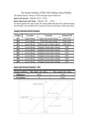
1. <strong>Jumper</strong>s function <strong>and</strong> its location<br />
Common<br />
Control<br />
DISP0<br />
DISP1<br />
<strong>Jumper</strong> Location Function<br />
JP2 Lower position Decode(With jumper)/non-decode(No jumper)<br />
JP3 Lower position O.V. test(T)or normal(N)<br />
JP1 Rear side High driving voltage selection<br />
JP5 Upper position High(HV)/Low(LV) driving voltage selection *1<br />
JP6 Upper position 0.6V(0.6V) voltage drop selection<br />
JP7 Upper position 1.2V(1V2) voltage drop selection<br />
JP8 Lower position High(HV)/Low(LV) driving voltage selection *1<br />
JP9 Lower position 0.6V(0.6V) voltage drop selection<br />
JP10 Lower position 1.2V(1V2) voltage drop selection<br />
Note 1: High(HV)/Low(LV) driving voltage selection jumper must be inserted with short<br />
metal bar horizontally.<br />
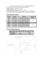
2. High driving voltage selection – JP1<br />
This jumper is located at the rear side <strong>of</strong> the module, please turn the module’s bottom face<br />
up when perform the setting.<br />
The upper three jumpers can only be selected one for shorted when usage. This setting only<br />
takes effective when the High(HV)/Low(LV) driving voltage selection jumper is set to HV<br />
position. When the jumper is positioned at LV, the driving voltage is 5V.<br />
When BOOST jumper is shorted, the driving voltage will be boosted about 5% from its<br />
nominal value can be used for compensation <strong>of</strong> line voltage drop.<br />
1
3. I/O address occupation <strong>and</strong> displays<br />
Module Display Mode I/O Occupied Model ID. Displays<br />
<strong>7SG</strong>1<br />
Decode 3 R.O. <strong>7SG</strong>1S 8 Digits<br />
Non-Decode 4 R.O. <strong>7SG</strong>1H 64 Segments<br />
<strong>7SG</strong>2<br />
Decode 5 R.O. <strong>7SG</strong>2S 16 Digits<br />
Non-Decode 8 R.O. <strong>7SG</strong>2H 128 Segments<br />
4. Display control<br />
The pattern <strong>of</strong> the LED display driven by the <strong>FBs</strong>-<strong>7SG</strong> LED display control module can be<br />
easily controlled by fill up the contents <strong>of</strong> the corresponding output registers. For more<br />
complicate applications, e.g. leading zero display control, message scrolling <strong>and</strong><br />
16-segment display control, we provide a h<strong>and</strong>y instruction TDSP to facilitate the user’s<br />
coding. Please refer the User’s manual for detail description <strong>of</strong> TDSP.<br />
Display control <strong>of</strong> <strong>7SG</strong>1 - decode mode<br />
The Rm at following table represent the first output register allocated for <strong>7SG</strong>1 module<br />
This register controls the decimal point display <strong>of</strong> every digit. D7~D0<br />
Rm+0 control the decimal point <strong>of</strong> 8 th ~ 1 st digit respectively. The decimal point<br />
will be lighted when the corresponding control bit is 1.<br />
This register controls the display <strong>of</strong> 4 th ~ 1 st digit. Every 4 bits(nibble)<br />
control one digit. D3~D0 control the first digit(right most), D7~D4<br />
Rm+1<br />
control the second digit, D11~D8 control the third digit while D15~D12<br />
control the fourth digit.<br />
This register can control the display <strong>of</strong> 8 th ~ 5 th digit. Every 4 bits(nibble)<br />
control one digit. D3~D0 control the 5<br />
Rm+2<br />
th digit, D7~D4 control the 6 th<br />
digit, D11~D8 control the 7 th digit while D15~D12 control the 8 th<br />
digit(left most).<br />
Please refer the contents <strong>of</strong> page 4 for the corresponding decoded display patterns for each 4 bits<br />
combination value.<br />
Display control <strong>of</strong> <strong>7SG</strong>1 - non-decode mode<br />
The Rm at following table represent the first output register allocated for <strong>7SG</strong>1 module<br />
This register controls the segment display <strong>of</strong> 2 nd ~ 1 st digit. Every 8<br />
Rm+0 bits(byte) control one digit. D7~D0 control the first digit(right most),<br />
D15~D8 control the second digit.<br />
This register controls the segment display <strong>of</strong> 4 th ~ 3 rd digit. Every 8<br />
bits(byte) control one digit. D7~D0 control the 3<br />
Rm+1<br />
rd digit, D15~D8<br />
control the 4 th digit.<br />
This register controls the segment display <strong>of</strong> 6 th ~ 5 th digit. Every 8<br />
bits(byte) control one digit. D7~D0 control the 5<br />
Rm+2<br />
th digit, D15~D8<br />
control the 6 th digit.<br />
This register controls the segment display <strong>of</strong> 8 th ~ 7 th digit. Every 8<br />
bits(byte) control one digit. D7~D0 control the 7<br />
Rm+3<br />
th digit, D15~D8<br />
control the 8 th digit(left most).<br />
Please refer the contents <strong>of</strong> page 5 for the corresponding driven segment for each control bits.<br />
2
Display control <strong>of</strong> <strong>7SG</strong>2 - decode mode<br />
The Rm at following table represent the first output register allocated for <strong>7SG</strong>2 module<br />
This register controls the decimal point display <strong>of</strong> every digit. D15~D0<br />
Rm+0 control the decimal point <strong>of</strong> 16 th ~ 1 st digit respectively. The decimal<br />
point will be lighted when the corresponding control bit is 1.<br />
This register controls the display <strong>of</strong> 4 th ~ 1 st digit. Every 4 bits(nibble)<br />
control one digit. D3~D0 control the first digit(right most), D7~D4<br />
Rm+1<br />
control the second digit, D11~D8 control the third digit while D15~D12<br />
control the fourth digit.<br />
This register controls the display <strong>of</strong> 8 th ~ 5 th digit. Every 4 bits(nibble)<br />
control one digit. D3~D0 control the first digit, D7~D4 control the<br />
Rm+2<br />
second digit, D11~D8 control the third digit while D15~D12 control the<br />
fourth digit.<br />
This register controls the display <strong>of</strong> 12 th ~ 9 th digit. Every 4 bits(nibble)<br />
control one digit. D3~D0 control the 9<br />
Rm+3<br />
th digit, D7~D4 control the 10 th<br />
digit, D11~D8 control the 11 th digit while D15~D12 control the 12 th<br />
digit.<br />
This register can control the display <strong>of</strong> 16 th ~ 13 th digit. Every 4<br />
bits(nibble) control one digit. D3~D0 control the 13<br />
Rm+4<br />
th digit, D7~D4<br />
control the 14 th digit, D11~D8 control the15 th digit while D15~D12<br />
control the 16 th digit(left most).<br />
Please refer the contents <strong>of</strong> page 4 for the corresponding decoded display patterns for each<br />
4 bits value<br />
Display control <strong>of</strong> <strong>7SG</strong>2 - non-decode mode<br />
The Rm at following table represent the first output register allocated for <strong>7SG</strong>2 module<br />
Rm+0<br />
Rm+1<br />
Rm+2<br />
Rm+3<br />
Rm+4<br />
Rm+5<br />
This register controls the segment display <strong>of</strong> 2 nd ~ 1 st digit. Every 8<br />
bits(byte) control one digit. D7~D0 control the first digit(right most),<br />
D15~D8 control the second digit.<br />
This register controls the segment display <strong>of</strong> 4 th ~ 3 rd digit. Every 8<br />
bits(byte) control one digit. D7~D0 control the 3 rd digit, D15~D8<br />
control the 4 th digit.<br />
This register controls the segment display <strong>of</strong> 6 th ~ 5 th digit. Every 8<br />
bits(byte) control one digit. D7~D0 control the 5 th digit, D15~D8<br />
control the 6 th digit.<br />
This register controls the segment display <strong>of</strong> 8 th ~ 7 th digit. Every 8<br />
bits(byte) control one digit. D7~D0 control the 7 th digit, D15~D8<br />
control the 8 th digit.<br />
This register controls the segment display <strong>of</strong> 10 th ~ 9 th digit. Every 8<br />
bits(byte) control one digit. D7~D0 control the 9 th digit, D15~D8<br />
control the 10 th digit.<br />
This register controls the segment display <strong>of</strong>12 th ~ 11 th digit. Every 8<br />
bits(byte) control one digit. D7~D0 control the 11 th digit, D15~D8<br />
control the 12 th digit.<br />
3
This register controls the segment display <strong>of</strong> 14 th ~ 13 th digit. Every 8<br />
bits(byte) control one digit. D7~D0 control the 13<br />
Rm+6<br />
th digit, D15~D8<br />
control the 14 th digit.<br />
This register controls the segment display <strong>of</strong> 16 th ~ 15 th digit. Every 8<br />
bits(byte) control one digit. D7~D0 control the 15<br />
Rm+7<br />
th digit, D15~D8<br />
control the 16 th digit(left most).<br />
Please refer the contents <strong>of</strong> page 5 for the corresponding driven segment for each control<br />
bits.<br />
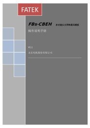
Display pattern for decoded mode<br />
Nibble value<br />
Segment data<br />
Segment<br />
Hexade<br />
Binary designation a b c d e f g<br />
cimal<br />
0 0000 1 1 1 1 1 1 0<br />
1 0001 0 1 1 0 0 0 0<br />
2 0010 1 1 0 1 1 0 1<br />
3 0011 1 1 1 1 0 0 1<br />
4 0100 0 1 1 0 0 1 1<br />
5 0101 1 0 1 1 0 1 1<br />
6 0110 1 0 1 1 1 1 1<br />
7 0111 1 1 1 0 0 1 0<br />
8 1000 1 1 1 1 1 1 1<br />
9 1001 1 1 1 1 0 1 1<br />
A 1010 0 0 0 0 0 0 1<br />
B 1011 1 0 0 1 1 1 1<br />
C 1100 0 1 1 0 1 1 1<br />
D 1101 0 0 0 1 1 0 1<br />
E 1110 0 0 0 1 1 1 1<br />
F 1111<br />
e<br />
f<br />
d<br />
g<br />
a<br />
c<br />
b<br />
P<br />
0 0 0 0 0 0 0<br />
Display<br />
pattern<br />
4
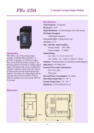
Following segment designation only apply for the LED display board provided by <strong>FATEK</strong>.<br />
Non-decode mode bit control designation for seven-segment display device<br />
D6<br />
a<br />
D1<br />
f<br />
b<br />
D5<br />
D0<br />
g<br />
D2<br />
e<br />
c<br />
D4<br />
d<br />
D3<br />
P<br />
D7<br />
Non-decode mode bit control designation for 16-segment display device<br />
5