Audio Codec with USB Interface, Mono ... - Texas Instruments
Audio Codec with USB Interface, Mono ... - Texas Instruments
Audio Codec with USB Interface, Mono ... - Texas Instruments

Create successful ePaper yourself
Turn your PDF publications into a flip-book with our unique Google optimized e-Paper software.
Burr-Brown <strong>Audio</strong><br />
PCM2912A<br />
www.ti.com.......................................................................................................................................................................................... SLES230–SEPTEMBER 2008<br />
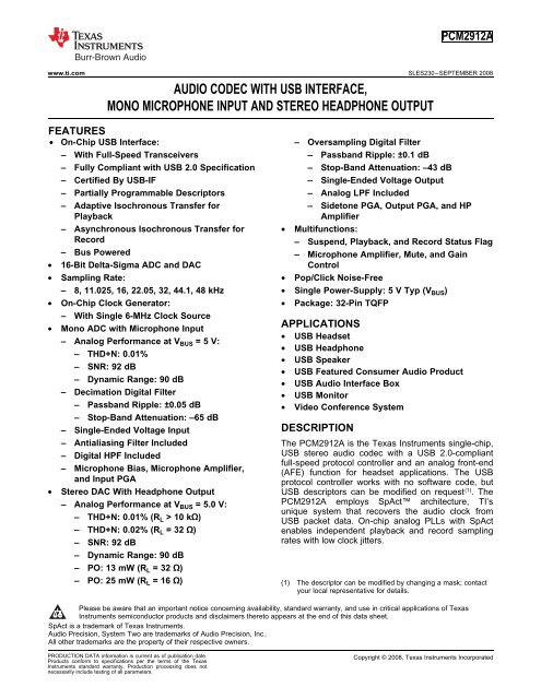
AUDIO CODEC WITH <strong>USB</strong> INTERFACE,<br />
MONO MICROPHONE INPUT AND STEREO HEADPHONE OUTPUT<br />
1FEATURES<br />
234• On-Chip <strong>USB</strong> <strong>Interface</strong>: – Oversampling Digital Filter<br />
– With Full-Speed Transceivers – Passband Ripple: ±0.1 dB<br />
– Fully Compliant <strong>with</strong> <strong>USB</strong> 2.0 Specification – Stop-Band Attenuation: –43 dB<br />
– Certified By <strong>USB</strong>-IF – Single-Ended Voltage Output<br />
– Partially Programmable Descriptors – Analog LPF Included<br />
– Adaptive Isochronous Transfer for – Sidetone PGA, Output PGA, and HP<br />
Playback Amplifier<br />
– Asynchronous Isochronous Transfer for • Multifunctions:<br />
Record – Suspend, Playback, and Record Status Flag<br />
– Bus Powered – Microphone Amplifier, Mute, and Gain<br />
• 16-Bit Delta-Sigma ADC and DAC Control<br />
• Sampling Rate: • Pop/Click Noise-Free<br />
– 8, 11.025, 16, 22.05, 32, 44.1, 48 kHz • Single Power-Supply: 5 V Typ (VBUS) • On-Chip Clock Generator: • Package: 32-Pin TQFP<br />
•<br />
– With Single 6-MHz Clock Source<br />
<strong>Mono</strong> ADC <strong>with</strong> Microphone Input<br />
– Analog Performance at VBUS = 5 V:<br />
– THD+N: 0.01%<br />
– SNR: 92 dB<br />
– Dynamic Range: 90 dB<br />
– Decimation Digital Filter<br />
APPLICATIONS<br />
• <strong>USB</strong> Headset<br />
• <strong>USB</strong> Headphone<br />
• <strong>USB</strong> Speaker<br />
• <strong>USB</strong> Featured Consumer <strong>Audio</strong> Product<br />
• <strong>USB</strong> <strong>Audio</strong> <strong>Interface</strong> Box<br />
• <strong>USB</strong> Monitor<br />
– Passband Ripple: ±0.05 dB • Video Conference System<br />
– Stop-Band Attenuation: –65 dB<br />
– Single-Ended Voltage Input<br />
DESCRIPTION<br />
– Antialiasing Filter Included The PCM2912A is the <strong>Texas</strong> <strong>Instruments</strong> single-chip,<br />
–<br />
–<br />
Digital HPF Included<br />
Microphone Bias, Microphone Amplifier,<br />
and Input PGA<br />
<strong>USB</strong> stereo audio codec <strong>with</strong> a <strong>USB</strong> 2.0-compliant<br />
full-speed protocol controller and an analog front-end<br />
(AFE) function for headset applications. The <strong>USB</strong><br />
protocol controller works <strong>with</strong> no software code, but<br />
• Stereo DAC With Headphone Output <strong>USB</strong> descriptors can be modified on request (1) . The<br />
– Analog Performance at VBUS = 5.0 V:<br />
– THD+N: 0.01% (RL > 10 kΩ)<br />
PCM2912A employs SpAct architecture, TI’s<br />
unique system that recovers the audio clock from<br />
<strong>USB</strong> packet data. On-chip analog PLLs <strong>with</strong> SpAct<br />
– THD+N: 0.02% (RL = 32 Ω) enables independent playback and record sampling<br />
– SNR: 92 dB<br />
rates <strong>with</strong> low clock jitters.<br />
– Dynamic Range: 90 dB<br />
– PO: 13 mW (RL = 32 Ω)<br />
– PO: 25 mW (RL = 16 Ω) (1) The descriptor can be modified by changing a mask; contact<br />
your local representative for details.<br />
1<br />
Please be aware that an important notice concerning availability, standard warranty, and use in critical applications of <strong>Texas</strong><br />
<strong>Instruments</strong> semiconductor products and disclaimers thereto appears at the end of this data sheet.<br />
2SpAct is a trademark of <strong>Texas</strong> <strong>Instruments</strong>.<br />
3<strong>Audio</strong> Precision, System Two are trademarks of <strong>Audio</strong> Precision, Inc..<br />
4All other trademarks are the property of their respective owners.<br />
PRODUCTION DATA information is current as of publication date. Copyright © 2008, <strong>Texas</strong> <strong>Instruments</strong> Incorporated<br />
Products conform to specifications per the terms of the <strong>Texas</strong><br />
<strong>Instruments</strong> standard warranty. Production processing does not<br />
necessarily include testing of all parameters.
PCM2912A<br />
SLES230–SEPTEMBER 2008.......................................................................................................................................................................................... www.ti.com<br />
This integrated circuit can be damaged by ESD. <strong>Texas</strong> <strong>Instruments</strong> recommends that all integrated circuits be handled <strong>with</strong><br />
appropriate precautions. Failure to observe proper handling and installation procedures can cause damage.<br />
ESD damage can range from subtle performance degradation to complete device failure. Precision integrated circuits may be more<br />
susceptible to damage because very small parametric changes could cause the device not to meet its published specifications.<br />
ABSOLUTE MAXIMUM RATINGS (1)(2)<br />
Over operating free-air temperature range (unless otherwise noted).<br />
RECOMMENDED OPERATING CONDITIONS<br />
Over operating free-air temperature range (unless otherwise noted).<br />
PARAMETER PCM2912A UNIT<br />
Supply voltage V BUS –0.3 to +6.5 V<br />
Ground voltage differences: BGND, PGND, AGND, HGND, DGND ±0.1 V<br />
Input voltage : V CCP, V CCA, V CCL, V CCR, V DD –0.3 to 4 V<br />
Digital input voltage<br />
PLAY, REC. –0.3 to 6.5 V<br />
D+, D–, XTI, XTO, MMUTE, TEST0, TEST1, POWER, MAMP, SSPND –0.3 to 4 V<br />
Analog input voltage MBIAS, V IN, V COM1, V COM2, V OUTL, V OUTR, FR, FL –0.3 to 4 V<br />
Input current (any pins except supplies) ±10 mA<br />
Ambient temperature under bias –40 to +125 °C<br />
Storage temperature –55 to +150 °C<br />
Junction temperature +150 °C<br />
(1) Stresses beyond those listed under Absolute Maximum Ratings may cause permanent damage to the device. These are stress ratings<br />
only, and functional operation of the device at these or any other conditions beyond those indicated under Recommended Operating<br />
Conditions is not implied. Exposure to absolute-maximum-rated conditions for extended periods may affect device reliability.<br />
(2) All voltage values are <strong>with</strong> respect to network ground terminal.<br />
PARAMETER MIN NOM MAX UNIT<br />
V BUS Supply voltage 4.35 5.00 5.25 V<br />
Analog input voltage, full scale (–0 dB) 0.43 V CCA V PP<br />
Digital input logic family TTL<br />
Digital input clock frequency 5.997 6.000 6.003 MHz<br />
Analog output load resistance 32 Ω<br />
Analog output load capacitance 100 pF<br />
Digital output load capacitance 10 pF<br />
T A Operating free-air temperature –25 +70 °C<br />
2 Submit Documentation Feedback Copyright © 2008, <strong>Texas</strong> <strong>Instruments</strong> Incorporated<br />
Product Folder Link(s): PCM2912A
ELECTRICAL CHARACTERISTICS<br />
All specifications at TA = +25°C, VBUS = 5 V, fS = 44.1 kHz, fIN = 1 kHz, and 16-bit data, unless otherwise noted.<br />
PCM2912A<br />
www.ti.com.......................................................................................................................................................................................... SLES230–SEPTEMBER 2008<br />
DIGITAL INPUT/OUTPUT<br />
INPUT LOGIC<br />
PCM2912A<br />
PARAMETER TEST CONDITIONS MIN TYP MAX UNIT<br />
Host interface Apply <strong>USB</strong> revision 2.0, full-speed<br />
<strong>Audio</strong> data format <strong>USB</strong> isochronous data format<br />
VIH 2 3.3<br />
Input logic level VDC<br />
VIL 0.8<br />
I IH (1)(2) V IN = 3.3 V ±10<br />
I IL (1)(2)<br />
I IH (3)<br />
Input logic current<br />
V IN = 0 V ±10<br />
V IN = 3.3 V 65 100<br />
I IL (3) V IN = 0 V ±10<br />
OUTPUT LOGIC<br />
V OH (1) I OH = –10 mA 2.9<br />
V OL (1) I OL = 10 mA 0.3<br />
V OH (4) Output logic level I OH = –2 mA 2.8 VDC<br />
V OL (4) I OL = 2 mA 0.5<br />
V OL (5)<br />
I OL = 8 mA 0.5<br />
I OH (5) Output leak current V IN = 5 V ±10 μA<br />
CLOCK FREQUENCY<br />
MICROPHONE BIAS<br />
Input clock frequency, XTI 5.997 6.000 6.003 MHz<br />
Output voltage 0.75 V CCA VDC<br />
Output current 2 mA<br />
Output noise R L = 1 kΩ 5 μV RMS<br />
(1) Pins 3, 4: D–, D+.<br />
(2) Pins 8, 23, 24, 27, 28: XTI, MAMP, POWER, TEST1, TEST0<br />
(3) Pin 30: MMUTE<br />
(4) Pins 7, 29: XTO, SSPND<br />
(5) Pins 31, 32: REC, PLAY.<br />
Copyright © 2008, <strong>Texas</strong> <strong>Instruments</strong> Incorporated Submit Documentation Feedback 3<br />
Product Folder Link(s): PCM2912A<br />
μA<br />
μA
PCM2912A<br />
SLES230–SEPTEMBER 2008.......................................................................................................................................................................................... www.ti.com<br />
ELECTRICAL CHARACTERISTICS (continued)<br />
All specifications at T A = +25°C, V BUS = 5 V, f S = 44.1 kHz, f IN = 1 kHz, and 16-bit data, unless otherwise noted.<br />
PCM2912A<br />
PARAMETER TEST CONDITIONS MIN TYP MAX UNIT<br />
ANALOG-TO-DIGITAL CONVERTER (ADC) CHARACTERISTICS<br />
Resolution 16 Bits<br />
<strong>Audio</strong> data channel 1 Channel<br />
Sampling frequency 8, 11.025, 16, 22.05, 32, 44.1, 48 kHz<br />
ADC Dynamic Performance (6)<br />
Total harmonic distortion plus<br />
THD+N V IN = –1 dB of 0.43 V CCA 0.01 0.02 %<br />
noise<br />
Dynamic range A-weighted 82 90 dB<br />
SNR Signal-to-noise ratio A-weighted 84 92 dB<br />
ADC DC Accuracy<br />
Analog Input<br />
Microphone Amplifier<br />
Input PGA<br />
Gain error ±2 ±10 % of FSR<br />
Bipolar zero error ±0 % of FSR<br />
Input voltage 0.43 V CCA V PP<br />
Center voltage 0.5 V CCA V<br />
Antialiasing filter frequency –3 dB 150 kHz<br />
response fIN = 20 kHz –0.08 dB<br />
Gain 0 20 dB<br />
Input impedance 20 kΩ<br />
Gain range –12 30 dB<br />
Gain step size 1 dB<br />
ADC Digital Filter Performance<br />
Passband 0.454 f S Hz<br />
Stop band 0.583 f S Hz<br />
Passband ripple ±0.02 dB<br />
Stop-band attenuation –65 dB<br />
Delay time 17.4/f S s<br />
HPF frequency response –3 dB 0.078 f S/1000 Hz<br />
(6) f IN = 1 kHz, using <strong>Audio</strong> Precision System Two, RMS mode <strong>with</strong> 20-kHz LPF, 400-Hz HPF in calculation. Mic amp = 0 dB,<br />
PGA = 0 dB.<br />
4 Submit Documentation Feedback Copyright © 2008, <strong>Texas</strong> <strong>Instruments</strong> Incorporated<br />
Product Folder Link(s): PCM2912A
PCM2912A<br />
www.ti.com.......................................................................................................................................................................................... SLES230–SEPTEMBER 2008<br />
ELECTRICAL CHARACTERISTICS (continued)<br />
All specifications at T A = +25°C, V BUS = 5 V, f S = 44.1 kHz, f IN = 1 kHz, and 16-bit data, unless otherwise noted.<br />
PCM2912A<br />
PARAMETER TEST CONDITIONS MIN TYP MAX UNIT<br />
DIGITAL-TO-ANALOG CONVERTER (DAC) CHARACTERISTICS<br />
Resolution 16 Bits<br />
<strong>Audio</strong> data channel 1, 2 Channel<br />
Sampling frequency 8, 11.025, 16, 22.05, 32, 44.1, 48 kHz<br />
DAC Dynamic Performance (7)<br />
THD+N<br />
Total harmonic distortion plus RL > 10 kΩ, VOUT = 0 dB of 0.6 VCCA 0.01 0.02 %<br />
noise RL = 32 Ω, VOUT = 0 dB of 0.55 VCCA 0.02 0.05 %<br />
Dynamic range EIAJ, A-Weighted 82 90 dB<br />
SNR Signal-to-noise ratio EIAJ, A-Weighted 84 92 dB<br />
DAC DC Accuracy<br />
Analog Output<br />
Channel separation R L > 10 kΩ 80 88 dB<br />
Gain mismatch<br />
channel-to-channel<br />
±2 ±10 % of FSR<br />
Gain error ±2 ±10 % of FSR<br />
Bipolar zero error ±3 % of FSR<br />
R L > 10 kΩ 0.6 V CCA<br />
Output voltage V PP<br />
R L = 32 Ω 0.55 V CCA<br />
Center voltage 0.5 V CCA V<br />
R L = 32 Ω 13<br />
Output power mW<br />
R L = 16 Ω 25<br />
Line 10 kΩ<br />
Load impedance (AC coupling) Headphone 16 32 Ω<br />
LPF frequency response<br />
Sidetone Programmable Attenuator<br />
–3 dB 140 kHz<br />
f = 20 kHz –0.1 dB<br />
Gain range –76 0 dB<br />
Gain step size 1 dB<br />
Output Programmable Attenuator<br />
Gain range –76 0 dB<br />
Gain step size 1 dB<br />
Analog Loopback Performance (8)<br />
THD+N<br />
Total harmonic distortion plus RL > 10 kΩ, VIN = 0 dB of 0.43 VCCA 0.01 0.02 %<br />
noise RL = 32 Ω, VIN = 0 dB of 0.43 VCCA 0.02 0.05 %<br />
Dynamic range EIAJ, A-weighted 82 90 dB<br />
SNR Signal-to-noise ratio EIAJ, A-weighted 84 92 dB<br />
DAC Digital Filter Performance<br />
Passband 0.445 f S Hz<br />
Stop band 0.555 f S Hz<br />
Passband ripple ±0.1 dB<br />
Stop-band attenuation –43 dB<br />
Delay time 14.3/f S s<br />
(7) f OUT = 1 kHz, using <strong>Audio</strong> Precision System Two, RMS mode <strong>with</strong> 20-kHz LPF, 400-Hz HPF. Output attenuator = 0 dB,<br />
Sidetone = Mute.<br />
(8) MIC Amp = 0 dB, Sidetone attenuator = 0 dB, Output attenuator = 0 dB.<br />
Copyright © 2008, <strong>Texas</strong> <strong>Instruments</strong> Incorporated Submit Documentation Feedback 5<br />
Product Folder Link(s): PCM2912A
PCM2912A<br />
SLES230–SEPTEMBER 2008.......................................................................................................................................................................................... www.ti.com<br />
ELECTRICAL CHARACTERISTICS (continued)<br />
All specifications at T A = +25°C, V BUS = 5 V, f S = 44.1 kHz, f IN = 1 kHz, and 16-bit data, unless otherwise noted.<br />
PCM2912A<br />
PARAMETER TEST CONDITIONS MIN TYP MAX UNIT<br />
POWER-SUPPLY REQUIREMENTS<br />
V BUS Voltage range Bus-powered 4.35 5.0 5.25 VDC<br />
Supply current<br />
Power dissipation<br />
ADC, DAC operation (R L = 32 Ω) 85 100 mA<br />
Suspend mode (9)<br />
220 300 μA<br />
ADC, DAC Operation 425 500 mW<br />
Suspend mode (9) 0.8 1 mW<br />
VCCP,VCCL, Internally-generated power<br />
VCCR,VCCA, 3 3.3 3.6 VDC<br />
supply voltage (10)<br />
VDD TEMPERATURE RANGE<br />
Operation temperature –25 +85 °C<br />
θ JA Thermal resistance 32-pin TQFP 80 °C/W<br />
(9) Under <strong>USB</strong> suspend state<br />
(10) Pins 5, 15, 19, 21, 26: V DD, V CCA, V CCL, V CCR, V CCP.<br />
6 Submit Documentation Feedback Copyright © 2008, <strong>Texas</strong> <strong>Instruments</strong> Incorporated<br />
Product Folder Link(s): PCM2912A
PGND<br />
V CCP<br />
TEST1<br />
TEST0<br />
SSPND<br />
MMUTE<br />
REC<br />
PLAY<br />
25<br />
26<br />
27<br />
28<br />
29<br />
30<br />
31<br />
32<br />
POWER<br />
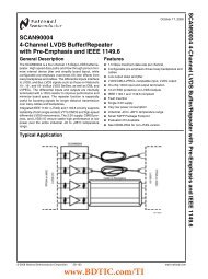
PIN ASSIGNMENTS<br />
24<br />
MAMP<br />
23<br />
22<br />
21<br />
20<br />
19<br />
18<br />
17<br />
1 2 3 4 5 6 7 8<br />
BGND<br />
VBUS VOUTR VCCR HGND<br />
VCCL VOUTL MBIAS<br />
D�<br />
PCM2912A<br />
D+<br />
V DD<br />
DGND<br />
XTO<br />
XTI<br />
16<br />
15<br />
14<br />
13<br />
12<br />
11<br />
10<br />
9<br />
V IN<br />
V CCA<br />
NC<br />
AGND<br />
V COM2<br />
V COM1<br />
FR<br />
FL<br />
PCM2912A<br />
www.ti.com.......................................................................................................................................................................................... SLES230–SEPTEMBER 2008<br />
PJT PACKAGE<br />
TQFP-32<br />
(TOP VIEW)<br />
Copyright © 2008, <strong>Texas</strong> <strong>Instruments</strong> Incorporated Submit Documentation Feedback 7<br />
Product Folder Link(s): PCM2912A
PCM2912A<br />
SLES230–SEPTEMBER 2008.......................................................................................................................................................................................... www.ti.com<br />
TERMINAL<br />
TERMINAL FUNCTIONS<br />
NAME PJT I/O DESCRIPTIONS<br />
BGND 1 — Reference for internal regulator.<br />
V BUS 2 — Connect to <strong>USB</strong> power (V BUS)<br />
D– 3 I/O <strong>USB</strong> differential input/output minus (1)<br />
D+ 4 I/O <strong>USB</strong> differential input/output plus (1)<br />
V DD 5 — Digital power supply (2)<br />
DGND 6 Digital ground<br />
XTO 7 O Crystal oscillator output<br />
XTI 8 I Crystal oscillator input (3)<br />
FL 9 — External filter pin of L-channel (optional)<br />
FR 10 — External filter pin of R-channel (optional)<br />
Common voltage for ADC, DAC, and analog front-end (V CCA/2). Decoupling capacitor should be connected to<br />
V COM1 11 — AGND.<br />
V COM2 12 — Common voltage for headphone (V CCA/2). Decoupling capacitor should be connected to AGND.<br />
AGND 13 — Analog ground<br />
NC 14 — Not connected<br />
V CCA 15 — Analog power supply<br />
V IN 16 I ADC microphone input<br />
MBIAS 17 O Microphone bias output (0.75 V CCA)<br />
V OUTL 18 O Headphone output for L-channel<br />
V CCL 19 — Analog power supply for headphone amplifier of L-channel (2)<br />
HGND 20 — Analog ground for headphone amplifier<br />
V CCR 21 — Analog power supply for headphone amplifier of R-channel (2)<br />
V OUTR 22 O Headphone output for R-channel<br />
MAMP 23 I Microphone preamplifier gain control (LOW: Preamplifier off, HIGH: Preamplifier on = +20 dB) (3)<br />
POWER 24 I Power consumption declaration select pin (LOW: 100 mA, HIGH: 500 mA) (3)<br />
PGND 25 — Analog ground for microphone bias, microphone amplifier, and PGA<br />
V CCP 26 — Analog power supply for PLL (2)<br />
TEST1 27 I Test pin. Must be set to HIGH (3)<br />
TEST0 28 I Test pin. Must be set to LOW (3)<br />
SSPND 29 O Suspend flag (LOW: Suspend, HIGH: Operational state)<br />
MMUTE 30 I Microphone mute control, active HIGH (LOW: Mute off, HIGH: Mute on) (4)<br />
REC 31 O Status output for record (LOW: Record, FLASH: Mute on recode, HIGH: Stop) (5)<br />
PLAY 32 O Status output for playback (LOW: Playback, FLASH: Mute on playback, HIGH: Stop) (5)<br />
(1) LV-TTL level<br />
(2) Connect decouple capacitor to corresponding ground.<br />
(3) 3.3-V CMOS level input.<br />
(4) 3.3-V CMOS level input <strong>with</strong> internal pulldown.<br />
(5) 5-V tolerant, open-drain.<br />
8 Submit Documentation Feedback Copyright © 2008, <strong>Texas</strong> <strong>Instruments</strong> Incorporated<br />
Product Folder Link(s): PCM2912A
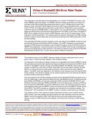
FUNCTIONAL BLOCK DIAGRAM<br />
MBIAS<br />
V IN<br />
V COM2<br />
V COM1<br />
V L<br />
OUT<br />
V R<br />
OUT<br />
FL<br />
FR<br />
MIC<br />
AMP<br />
+20/0 dB<br />
MIC<br />
BIAS<br />
HP AMP 15 mW (at 32 �)<br />
ATT 0 dB ~ –76 dB<br />
in 1 dB steps <strong>with</strong> Mute<br />
XTI<br />
6.000 MHz<br />
PGA + 30 dB ~ –12 dB<br />
in 1 dB steps<br />
�<br />
ATT 0 dB ~ –76 dB<br />
in 1 dB steps <strong>with</strong> Mute<br />
�<br />
XTO<br />
BGND<br />
V REF<br />
ADC<br />
DAC<br />
V /V /V L/V R/V<br />
CCA CCP CC CC DD<br />
PLL (x16)<br />
Selector<br />
Selector<br />
5 V to 3.3 V<br />
Voltage<br />
Regulator<br />
FIFO<br />
Analog<br />
PLL<br />
Analog<br />
PLL<br />
FIFO<br />
96 MHz Tracker<br />
AGND/ HGND/ PGND/DGND<br />
Power<br />
Manager<br />
ISO-In<br />
Endpoint<br />
Control<br />
Endpoint<br />
ISO-Out<br />
Endpoint<br />
<strong>USB</strong> Protocol<br />
Controller<br />
(SpAct ® )<br />
XCVR<br />
<strong>USB</strong> SIE<br />
PCM2912A<br />
www.ti.com.......................................................................................................................................................................................... SLES230–SEPTEMBER 2008<br />
SSPND<br />
V BUS<br />
D+<br />
D–<br />
POWER<br />
MAMP<br />
MMUTE<br />
Copyright © 2008, <strong>Texas</strong> <strong>Instruments</strong> Incorporated Submit Documentation Feedback 9<br />
Product Folder Link(s): PCM2912A<br />
PLAY<br />
REC<br />
TEST0<br />
TEST1
PCM2912A<br />
SLES230–SEPTEMBER 2008.......................................................................................................................................................................................... www.ti.com<br />
TYPICAL CHARACTERISTICS: INTERNAL FILTER<br />
All specifications at TA = +25°C, VBUS = 5 V, fS = 44.1 kHz, fIN = 1 kHz, and 16-bit data, unless otherwise noted.<br />
ADC Digital Decimation Filter Frequency Response<br />
Amplitude - dB<br />
Amplitude - dB<br />
0<br />
�40<br />
�80<br />
�120<br />
�160<br />
0 8 16 24 32<br />
0.2<br />
0<br />
�0.2<br />
�0.4<br />
�0.6<br />
OVERALL CHARACTERISTIC STOP BAND ATTENUATION<br />
Normalized Frequency - x f S<br />
�0.8<br />
0 0.1 0.2 0.3 0.4 0.5<br />
Normalized Frequency - x f S<br />
Amplitude - dB<br />
Amplitude - dB<br />
0<br />
�20<br />
�40<br />
�60<br />
�80<br />
�100<br />
0 0.2 0.4 0.6 0.8 1.0<br />
0<br />
�4<br />
�8<br />
�12<br />
�16<br />
Normalized Frequency - x f S<br />
Figure 1. Figure 2.<br />
PASSBAND RIPPLE TRANSIENT BAND RESPONSE<br />
�20<br />
0.46 0.48 0.50 0.52 0.54<br />
Normalized Frequency - x f S<br />
Figure 3. Figure 4.<br />
10 Submit Documentation Feedback Copyright © 2008, <strong>Texas</strong> <strong>Instruments</strong> Incorporated<br />
Product Folder Link(s): PCM2912A
ADC Digital High-Pass Filter Frequency Response<br />
Amplitude - dB<br />
0<br />
�20<br />
�40<br />
�60<br />
�80<br />
�100<br />
0 0.1 0.2 0.3 0.4<br />
Normalized Frequency - x f /1000<br />
S<br />
ADC Analog Antialiasing Filter Frequency Response<br />
Amplitude - dB<br />
0<br />
�10<br />
�20<br />
�30<br />
�40<br />
�50<br />
1 10 100 1000 10000<br />
f - Frequency - kHz<br />
Amplitude - dB<br />
Amplitude - dB<br />
0<br />
�0.2<br />
�0.4<br />
�0.6<br />
�0.8<br />
�1.0<br />
0 1 2 3 4<br />
0<br />
�0.2<br />
�0.4<br />
�0.6<br />
�0.8<br />
�1.0<br />
Normalized Frequency - x f /1000<br />
S<br />
0.01 0.1 1 10 100<br />
f - Frequency - kHz<br />
PCM2912A<br />
www.ti.com.......................................................................................................................................................................................... SLES230–SEPTEMBER 2008<br />
TYPICAL CHARACTERISTICS: INTERNAL FILTER (continued)<br />
All specifications at T A = +25°C, V BUS = 5 V, f S = 44.1 kHz, f IN = 1 kHz, and 16-bit data, unless otherwise noted.<br />
STOP BAND CHARACTERISTIC PASSBAND CHARACTERISTIC<br />
Figure 5. Figure 6.<br />
STOP BAND CHARACTERISTIC PASSBAND CHARACTERISTIC<br />
Figure 7. Figure 8.<br />
Copyright © 2008, <strong>Texas</strong> <strong>Instruments</strong> Incorporated Submit Documentation Feedback 11<br />
Product Folder Link(s): PCM2912A
PCM2912A<br />
SLES230–SEPTEMBER 2008.......................................................................................................................................................................................... www.ti.com<br />
DAC Digital Interpolation Filter Frequency Response<br />
Amplitude - dB<br />
0<br />
�20<br />
�40<br />
�60<br />
�80<br />
�100<br />
TYPICAL CHARACTERISTICS: INTERNAL FILTER (continued)<br />
All specifications at T A = +25°C, V BUS = 5 V, f S = 44.1 kHz, f IN = 1 kHz, and 16-bit data, unless otherwise noted.<br />
STOP BAND ATTENUATION PASSBAND RIPPLE<br />
0 1 2 3 4<br />
Normalized Frequency - x f S<br />
Amplitude - dB<br />
0<br />
�4<br />
�8<br />
�12<br />
�16<br />
�20<br />
Amplitude - dB<br />
0.2<br />
0<br />
�0.2<br />
�0.4<br />
�0.6<br />
�0.8<br />
0.46 0.48 0.50 0.52 0.54<br />
Normalized Frequency - x f S<br />
0 0.1 0.2 0.3 0.4 0.5<br />
Normalized Frequency - x f S<br />
Figure 9. Figure 10.<br />
TRANSIENT BAND RESPONSE<br />
Figure 11.<br />
12 Submit Documentation Feedback Copyright © 2008, <strong>Texas</strong> <strong>Instruments</strong> Incorporated<br />
Product Folder Link(s): PCM2912A
DAC Analog FIR Filter Frequency Response<br />
Amplitude - dB<br />
0<br />
�10<br />
�20<br />
�30<br />
�40<br />
�50<br />
0 8 16 24 32<br />
Normalized Frequency - x f S<br />
DAC Analog Low-Pass Filter Frequency Response<br />
Amplitude - dB<br />
0<br />
�10<br />
�20<br />
�30<br />
�40<br />
�50<br />
1 10 100 1000 10000<br />
f - Frequency - kHz<br />
Amplitude - dB<br />
Amplitude - dB<br />
0.2<br />
0<br />
�0.2<br />
�0.4<br />
�0.6<br />
�0.8<br />
0<br />
�0.2<br />
�0.4<br />
�0.6<br />
�0.8<br />
�1.0<br />
0 0.1 0.2 0.3 0.4 0.5<br />
Normalized Frequency - x f S<br />
0.01 0.1 1 10 100<br />
f - Frequency - kHz<br />
PCM2912A<br />
www.ti.com.......................................................................................................................................................................................... SLES230–SEPTEMBER 2008<br />
TYPICAL CHARACTERISTICS: INTERNAL FILTER (continued)<br />
All specifications at T A = +25°C, V BUS = 5 V, f S = 44.1 kHz, f IN = 1 kHz, and 16-bit data, unless otherwise noted.<br />
STOP BAND CHARACTERISTIC PASSBAND CHARACTERISTIC<br />
Figure 12. Figure 13.<br />
STOP BAND CHARACTERISTIC PASSBAND CHARACTERISTIC<br />
Figure 14. Figure 15.<br />
Copyright © 2008, <strong>Texas</strong> <strong>Instruments</strong> Incorporated Submit Documentation Feedback 13<br />
Product Folder Link(s): PCM2912A
PCM2912A<br />
SLES230–SEPTEMBER 2008.......................................................................................................................................................................................... www.ti.com<br />
ADC<br />
THD+N - Total Harmonic Distortion + Noise - %<br />
THD+N - Total Harmonic Distortion + Noise - %<br />
TYPICAL CHARACTERISTICS<br />
All specifications at TA = +25°C, VBUS = 5 V, fS = 44.1 kHz, fIN = 1 kHz, and 16-bit data, unless otherwise noted.<br />
0.010<br />
0.009<br />
0.008<br />
0.007<br />
0.006<br />
0.005<br />
0.004<br />
0.003<br />
0.010<br />
0.009<br />
0.008<br />
0.007<br />
0.006<br />
0.005<br />
0.004<br />
0.003<br />
THD+N AT –1 dB DYNAMIC RANGE AND SIGNAL-TO-NOISE RATIO<br />
vs TEMPERATURE vs TEMPERATURE<br />
�50 �25 0 25 50 75 100<br />
T - Free-Air Temperature - °C<br />
A<br />
4.2 4.4 4.6 4.8 5.0 5.2 5.4<br />
V - Supply Voltage - V<br />
BUS<br />
Dynamic Range and SNR - dB<br />
96<br />
94<br />
92<br />
90<br />
88<br />
86<br />
SNR<br />
Dynamic Range<br />
�50 �25 0 25 50 75 100<br />
TA - Free-Air Temperature - °C<br />
Figure 16. Figure 17.<br />
THD+N AT –1 dB DYNAMIC RANGE AND SIGNAL-TO-NOISE RATIO<br />
vs SUPPLY VOLTAGE vs SUPPLY VOLTAGE<br />
Dynamic Range and SNR - dB<br />
98<br />
96<br />
94<br />
92<br />
90<br />
88<br />
SNR<br />
Dynamic Range<br />
86<br />
4.2 4.4 4.6 4.8 5.0 5.2 5.4<br />
V - Supply Voltage - V<br />
BUS<br />
Figure 18. Figure 19.<br />
14 Submit Documentation Feedback Copyright © 2008, <strong>Texas</strong> <strong>Instruments</strong> Incorporated<br />
Product Folder Link(s): PCM2912A
THD+N - Total Harmonic Distortion + Noise - %<br />
DAC<br />
THD+N - Total Harmonic Distortion + Noise - %<br />
0.010<br />
0.009<br />
0.008<br />
0.007<br />
0.006<br />
0.005<br />
0.004<br />
0.003<br />
0.010<br />
0.009<br />
0.008<br />
0.007<br />
0.006<br />
0.005<br />
0.004<br />
0.003<br />
30 35 40 45 50<br />
f - Sampling Frequency - kHz<br />
S<br />
�50 �25 0 25 50 75 100<br />
T - Free-Air Temperature - °C<br />
A<br />
Dynamic Range and SNR - dB<br />
Dynamic Range and SNR - dB<br />
98<br />
96<br />
94<br />
92<br />
90<br />
88<br />
SNR<br />
Dynamic Range<br />
86<br />
30 35 40 45 50<br />
96<br />
94<br />
92<br />
90<br />
88<br />
f - Sampling Frequency - kHz<br />
S<br />
SNR<br />
Dynamic Range<br />
86<br />
�50 �25 0 25 50 75 100<br />
T - Free-Air Temperature - °C<br />
A<br />
PCM2912A<br />
www.ti.com.......................................................................................................................................................................................... SLES230–SEPTEMBER 2008<br />
TYPICAL CHARACTERISTICS (continued)<br />
All specifications at T A = +25°C, V BUS = 5 V, f S = 44.1 kHz, f IN = 1 kHz, and 16-bit data, unless otherwise noted.<br />
THD+N AT –1 dB DYNAMIC RANGE AND SIGNAL-TO-NOISE RATIO<br />
vs SAMPLING FREQUENCY vs SAMPLING FREQUENCY<br />
Figure 20. Figure 21.<br />
THD+N AT 0 dB DYNAMIC RANGE AND SIGNAL-TO-NOISE RATIO<br />
vs TEMPERATURE vs TEMPERATURE<br />
Figure 22. Figure 23.<br />
Copyright © 2008, <strong>Texas</strong> <strong>Instruments</strong> Incorporated Submit Documentation Feedback 15<br />
Product Folder Link(s): PCM2912A
PCM2912A<br />
SLES230–SEPTEMBER 2008.......................................................................................................................................................................................... www.ti.com<br />
THD+N - Total Harmonic Distortion + Noise - %<br />
THD+N - Total Harmonic Distortion + Noise - %<br />
0.010<br />
0.009<br />
0.008<br />
0.007<br />
0.006<br />
0.005<br />
0.004<br />
0.003<br />
0.010<br />
0.009<br />
0.008<br />
0.007<br />
0.006<br />
0.005<br />
0.004<br />
0.003<br />
4.2 4.4 4.6 4.8 5.0 5.2 5.4<br />
V - Supply Voltage - V<br />
BUS<br />
30 35 40 45 50<br />
f - Sampling Frequency - kHz<br />
S<br />
TYPICAL CHARACTERISTICS (continued)<br />
All specifications at T A = +25°C, V BUS = 5 V, f S = 44.1 kHz, f IN = 1 kHz, and 16-bit data, unless otherwise noted.<br />
THD+N AT 0 dB DYNAMIC RANGE AND SIGNAL-TO-NOISE RATIO<br />
vs SUPPLY VOLTAGE vs SUPPLY VOLTAGE<br />
Dynamic Range and SNR - dB<br />
Dynamic Range and SNR - dB<br />
98<br />
96<br />
94<br />
92<br />
90<br />
88<br />
86<br />
98<br />
96<br />
94<br />
92<br />
90<br />
88<br />
SNR<br />
Dynamic Range<br />
4.2 4.4 4.6 4.8 5.0 5.2 5.4<br />
V - Supply Voltage - V<br />
BUS<br />
Figure 24. Figure 25.<br />
THD+N AT 0 dB DYNAMIC RANGE AND SIGNAL-TO-NOISE RATIO<br />
vs SAMPLING FREQUENCY vs SAMPLING FREQUENCY<br />
SNR<br />
Dynamic Range<br />
86<br />
30 35 40 45 50<br />
f - Sampling Frequency - kHz<br />
S<br />
Figure 26. Figure 27.<br />
16 Submit Documentation Feedback Copyright © 2008, <strong>Texas</strong> <strong>Instruments</strong> Incorporated<br />
Product Folder Link(s): PCM2912A
Supply Current<br />
Operational Current - mA<br />
100<br />
90<br />
80<br />
70<br />
60<br />
Operational Current<br />
Suspend Current<br />
50<br />
0<br />
4.2 4.4 4.6 4.8 5.0 5.2 5.4<br />
V - Supply Voltage - V<br />
BUS<br />
Suspend Current - mA<br />
0.40<br />
0.35<br />
0.30<br />
0.25<br />
0.20<br />
0.15<br />
0.10<br />
0.5<br />
0.4<br />
0.3<br />
0.2<br />
0.1<br />
Suspend Current - mA<br />
Operational Current - mA<br />
100<br />
90<br />
80<br />
70<br />
60<br />
<strong>USB</strong> spec limit for device = 0.3 mA<br />
�40 �20 0 20 40 60 80 100<br />
T - Free-Air Temperature - °C<br />
A<br />
50<br />
30 35 40 45 50<br />
f - Sampling Frequency - kHz<br />
S<br />
PCM2912A<br />
www.ti.com.......................................................................................................................................................................................... SLES230–SEPTEMBER 2008<br />
TYPICAL CHARACTERISTICS (continued)<br />
All specifications at T A = +25°C, V BUS = 5 V, f S = 44.1 kHz, f IN = 1 kHz, and 16-bit data, unless otherwise noted.<br />
SUPPLY CURRENT SUPPLY CURRENT<br />
vs SUPPLY VOLTAGE vs SAMPLING FREQUENCY<br />
Figure 28. Figure 29.<br />
SUPPLY CURRENT<br />
vs TEMPERATURE AT SUSPEND MODE<br />
Figure 30.<br />
Copyright © 2008, <strong>Texas</strong> <strong>Instruments</strong> Incorporated Submit Documentation Feedback 17<br />
Product Folder Link(s): PCM2912A
PCM2912A<br />
SLES230–SEPTEMBER 2008.......................................................................................................................................................................................... www.ti.com<br />
<strong>USB</strong> INTERFACE<br />
GENERAL DESCRIPTION<br />
Control data and audio data are transferred to the PCM2912A via D+ (pin 4) and D– (pin 3). All data transferred<br />
to/from the PCM2912A are performed at full speed. Table 1 summarizes the device descriptor. The device<br />
descriptor can be modified on request.<br />
Table 1. Device Descriptor<br />
<strong>USB</strong> revision 2.0 compliant<br />
Device class 0x00 (device defined in interface level)<br />
Device sub class 0x00 (not specified)<br />
Device protocol 0x00 (not specified)<br />
Max packet size for endpoint 0 8-byte<br />
Vendor ID 0x08BB<br />
Product ID 0x2912<br />
Device release number 0x0100 (1.00)<br />
Number of configurations 1<br />
Vendor string String #1 (refer to Table 3)<br />
Product string String #2 (refer to Table 3)<br />
Serial number Not supported<br />
Table 2 lists the configuration descriptor. The configuration descriptor can be modified on request.<br />
<strong>Interface</strong> Three interfaces<br />
Table 2. Configuration Descriptor<br />
Power attribute 0x80 (Bus powered, no remote wakeup)<br />
Max power 0x32 (100 mA at POWER = Low) / 0xFA (500mA at POWER = High)<br />
Table 3 summarizes the string descriptor. The string descriptor can be modified on request.<br />
#0 0x0409<br />
Table 3. String Descriptor<br />
#1 Burr-Brown from TI<br />
#2 <strong>USB</strong> audio CODEC<br />
18 Submit Documentation Feedback Copyright © 2008, <strong>Texas</strong> <strong>Instruments</strong> Incorporated<br />
Product Folder Link(s): PCM2912A
Device Configuration<br />
<strong>Interface</strong> #0<br />
Endpoint #0<br />
Default Endpoint<br />
Endpoint #1<br />
(IF #1)<br />
<strong>Audio</strong> Streaming <strong>Interface</strong><br />
Endpoint #1<br />
(IF #1)<br />
<strong>Audio</strong> Streaming <strong>Interface</strong><br />
IT<br />
TID3<br />
OT<br />
TIDB<br />
�<br />
UID4<br />
�<br />
UIDA<br />
FU<br />
FU<br />
FU<br />
UID5<br />
UID2<br />
UID8<br />
Standard <strong>Audio</strong> Control <strong>Interface</strong> (IF #0)<br />
OT<br />
TID6<br />
IT<br />
TID1<br />
IT<br />
TID7<br />
PCM2912A<br />
www.ti.com.......................................................................................................................................................................................... SLES230–SEPTEMBER 2008<br />
Figure 31 illustrates the <strong>USB</strong> audio function topology. The PCM2912A has three interfaces. Each interface is<br />
constructed <strong>with</strong> some alternative settings.<br />
Figure 31. <strong>USB</strong> <strong>Audio</strong> Function Topology<br />
Analog Out<br />
Analog In<br />
<strong>Interface</strong> #0 is the control interface. Alternative setting #0 is the only possible setting for interface #0. Alternative<br />
setting #0 describes the standard audio control interface. The audio control interface is constructed <strong>with</strong> a series<br />
of terminal connections. The PCM2912A has the following 10 terminals:<br />
• Input terminal (Terminal ID#1) for audio analog input for sidetone<br />
• Feature unit (Unit ID#2) for sidetone PGA<br />
• Input terminal (Terminal ID#3) for isochronous out stream<br />
• Mixer unit (Unit ID#4) for sidetone mixing<br />
• Feature unit (Unit ID#5) for analog output PGA<br />
• Output terminal (Terminal ID#6) for audio analog output<br />
• Input terminal (Terminal ID#7) for audio analog input<br />
• Feature unit (Unit ID#8) for analog input PGA<br />
• Mixer unit (Unit ID#A) for analog input<br />
• Output terminal (Terminal ID#B) for isochronous in stream<br />
Copyright © 2008, <strong>Texas</strong> <strong>Instruments</strong> Incorporated Submit Documentation Feedback 19<br />
Product Folder Link(s): PCM2912A
PCM2912A<br />
SLES230–SEPTEMBER 2008.......................................................................................................................................................................................... www.ti.com<br />
Input terminal #3 is defined as <strong>USB</strong> stream (terminal type 0x0101). Input terminal #3 can accept two-channel<br />
audio streams constructed by the left and right channels. Output terminal #6 is defined as a speaker (terminal<br />
type 0x0301). Input terminals #1 and #7 are defined as Microphone (terminal type 0x0201). Physically, these two<br />
input terminals are the same input, but logically duplicated. Output terminal B is defined as a <strong>USB</strong> stream<br />
(terminal type 0x0101). Output terminal B is a single-channel audio stream. Mixer unit #4 multiplexes the analog<br />
input (sidetone) and the audio data of the digital-to-analog converter (DAC). Mixer unit A is placed in front of<br />
output terminal B. Mixer unit A has no impact on recording data. Mixer units #4 and A do not have programming<br />
capability.<br />
Feature unit #5 supports the following sound control features for analog outputs:<br />
• Volume control<br />
• Mute control<br />
The built-in volume controller can be manipulated by an audio-class-specific request from 0 dB to –76 dB in<br />
steps of 1 dB. An individual (L and R) channel can be set for different values. The built-in mute controller can be<br />
manipulated by an audio-class-specific request. Only the master mute control request is acceptable.<br />
Feature unit #2 supports the following sound control features for analog input (sidetone):<br />
• Volume control<br />
• Mute control<br />
The built-in volume controller can be manipulated by an audio-class-specific request from 0 dB to –76 dB in 1-dB<br />
steps. Only the master volume control is acceptable. The built-in mute controller can be manipulated by<br />
audio-class-specific request. Only the master mute control request is acceptable.<br />
Feature unit #8 supports the following sound control features for analog input (microphone record input):<br />
• Volume control<br />
• Mute control<br />
The built-in analog volume controller can be manipulated by an audio-class-specific request from +30 dB to –12<br />
dB in 1-dB steps. The built-in mute controller can be manipulated by an audio-class-specific request. Only the<br />
master mute control request is acceptable.<br />
<strong>Interface</strong> #1<br />
<strong>Interface</strong> #1 is the audio streaming interface for data output. Table 4 lists the three alternative settings for<br />
<strong>Interface</strong> #1. Alternative setting #0 is the zero bandwidth setting. All other alternative settings are operational<br />
settings.<br />
<strong>Interface</strong> #2<br />
Table 4. <strong>Interface</strong> #1 Alternative Settings<br />
ALTERNATIVE<br />
SETTING DATA FORMAT TRANSFER MODE SAMPLING RATE (kHz)<br />
00 Zero Bandwidth<br />
01 16 bit Stereo 2s complement (PCM) Adaptive<br />
02 16 bit <strong>Mono</strong> 2s complement (PCM) Adaptive<br />
8, 11.025, 16, 22.05, 32, 44.1,<br />
48<br />
8, 11.025, 16, 22.05, 32, 44.1,<br />
48<br />
<strong>Interface</strong> #2 is the audio streaming interface for data output. Table 5 shows the two alternative settings for<br />
<strong>Interface</strong> #2. Alternative setting #0 is the Zero Band Width setting. Alternative setting #1 is an operational setting.<br />
Table 5. <strong>Interface</strong> #2 Alternative Settings<br />
ALTERNATIVE<br />
SETTING DATA FORMAT TRANSFER MODE SAMPLING RATE (kHz)<br />
00 Zero Bandwidth<br />
01 16 bit <strong>Mono</strong> 2s complement (PCM) Asynchronous<br />
8, 11.025, 16, 22.05, 32,<br />
44.1, 48<br />
20 Submit Documentation Feedback Copyright © 2008, <strong>Texas</strong> <strong>Instruments</strong> Incorporated<br />
Product Folder Link(s): PCM2912A
Endpoints<br />
Internal Regulator<br />
Clock and Reset<br />
DAC<br />
ADC<br />
Microphone Bias<br />
PCM2912A<br />
www.ti.com.......................................................................................................................................................................................... SLES230–SEPTEMBER 2008<br />
The PCM2912A has the following three endpoints:<br />
• Control endpoint (EP #0)<br />
• Isochronous out audio data stream endpoint (EP #1)<br />
• Isochronous in audio data stream endpoint (EP #2)<br />
The control endpoint is the default endpoint. The control endpoint controls all functions of the PCM2912A by the<br />
standard <strong>USB</strong> request and <strong>USB</strong> audio class-specific request from the host. The isochronous out audio data<br />
stream endpoint is an audio sink endpoint, which receives the PCM audio data. The isochronous out audio data<br />
stream endpoint accepts the asynchronous transfer mode. The isochronous in audio data stream endpoint is an<br />
audio source endpoint, which transmits the PCM audio data. The isochronous in audio data stream endpoint<br />
uses synchronous transfer mode.<br />
All required power sources are generated by five internal regulators.<br />
Each regulator generates 3.3 V (typical, <strong>with</strong>out load) from V BUS (pin 2). Each regulator has an output pin and a<br />
ground return pin (as described in Table 6); this pair must be decoupled <strong>with</strong> an appropriate capacitor. Note that<br />
this capacitance affects inrush-current limitation. One band-gap reference circuit supplies reference voltage for all<br />
regulators. BGND (pin 1) is provided for reference ground of the band-gap reference.<br />
Table 6. Internal Regulator Summary<br />
SUPPLIED CIRCUIT OUTPUT RETURN<br />
Digital V DD (pin 5) DGND (pin 6)<br />
Analog V CCA (pin 15) AGND (pin 13)<br />
Headphone (L-ch) V CCL (pin 19) HGND (pin 20)<br />
Headphone (R-ch) V CCR (pin 21) HGND (pin 20)<br />
PLL V CCP (pin 26) PGND (pin 25)<br />
The PCM2912A requires a 6-MHz (±500 ppm) clock for <strong>USB</strong> function and audio function, which can be<br />
generated from a built-in crystal oscillator <strong>with</strong> a 6-MHz crystal resonator. The 6-MHz crystal resonator must be<br />
connected to XTI (pin 8) and XTO (pin 7) <strong>with</strong> one high (1-MΩ) resistor and two small capacitors, whose<br />
capacitance depends on the load capacitance of the crystal resonator. An external clock can be supplied through<br />
XTI; if an external clock is supplied, XTO must be left open. Because there is no clock disabling signal, using the<br />
external clock supply is not recommended. SSPND (pin 29) is unable to use clock disabling.<br />
The PCM2912A has an internal power-on-reset circuit, which works automatically when V BUS (pin 2) exceeds 2.5<br />
V, typical (2.2 V to 2.7 V), and approximately 700 μs is required until the internal reset is released.<br />
The PCM2912A has a stereo delta-sigma DAC that uses a 64-f S oversampling technique <strong>with</strong> an 8-f S<br />
oversampling digital filter. DAC outputs are provided through the headphone amplifier; V OUTL (pin 18) and V OUTR<br />
(pin 22) provide 13 mW at 32 Ω and 0.6 V CCL/V CCR V PP at a 10-kΩ load.<br />
The PCM2912A has a mono delta-sigma ADC that uses a 64-f S oversampling technique <strong>with</strong> a 1/64-f S<br />
decimation digital filter. The microphone input, V IN (pin 16), is fed to the ADC through a +20-dB microphone<br />
amplifier and the PGA, which has +30 dB to –12 dB in 1-dB steps.<br />
The PCM2912A has a microphone bias generator, which provides a low-noise, 0.75-V CCA, 2-mA source current<br />
output <strong>with</strong> appropriate output impedance for electret-microphone driving. This output, MBIAS (pin 17), should be<br />
bypassed to AGND (pin 13) through an appropriate capacitor to reduce the output noise level.<br />
Copyright © 2008, <strong>Texas</strong> <strong>Instruments</strong> Incorporated Submit Documentation Feedback 21<br />
Product Folder Link(s): PCM2912A
PCM2912A<br />
SLES230–SEPTEMBER 2008.......................................................................................................................................................................................... www.ti.com<br />
Microphone Amplifier<br />
The PCM2912A has a low-noise, single-ended, mono microphone amplifier <strong>with</strong> a mute function that is controlled<br />
by MUTE (pin 30). The signal gain is selectable by MAMP (pin 23). The noise level at the input node is 5 μV RMS,<br />
and the input impedance is 20 kΩ.<br />
Input PGA<br />
The PCM2912A also has a low-noise input, programmable gain amplifier (PGA) for the microphone amplifier<br />
output/ADC input, <strong>with</strong> a gain range of +30 dB to –12 dB in 1dB/step.<br />
Sidetone Programmable Attenuator<br />
The PCM2912A has a low-noise, sidetone programmable attenuator <strong>with</strong> a mute function for the sidetone signal<br />
path (microphone amplifier output to output PGA input), and a gain range of 0 dB to –76 dB in 1 dB/step.<br />
Output Programmable Attenuator<br />
The PCM2912A has a low-noise output programmable attenuator <strong>with</strong> a mute function for mixed signal, which<br />
affects DAC output signal and sidetone signal. The output PGA gain range is 0 dB to –76 dB in 1 dB/step.<br />
V COM1 and V CCM2<br />
V COM2 (pin 12) is provided for the center voltage of the headphone amplifier. V COM1 (pin 11) is provided for the<br />
center voltage of all other analog circuits. Each V COM pin must be decoupled <strong>with</strong> an appropriate capacitor.<br />
Because the headphone output is disconnected when entering the suspend state, determining the capacitance is<br />
important to prevent pop noise, especially for V COM2 (pin 12). The equivalent resistance of V COM2 is 500 kΩ, and<br />
V COM1 is 15 kΩ.<br />
Filter Pins<br />
FL (pin 9) and FR (pin 10) are provided to make a low-pass filter (LPF) to decrease the DAC outband noise, as<br />
shown in Figure 32. This filter is optional.<br />
DAC<br />
10 k�<br />
10 k�<br />
FR/FL<br />
C F<br />
Side Tone<br />
V COM<br />
Figure 32. Filter Circuit<br />
22 Submit Documentation Feedback Copyright © 2008, <strong>Texas</strong> <strong>Instruments</strong> Incorporated<br />
Product Folder Link(s): PCM2912A<br />
20 k�<br />
–<br />
+<br />
20 k�
INTERFACE SEQUENCE<br />
Power-On, Attach, and Play Back Sequence<br />
V (pin 2)<br />
BUS<br />
0 V<br />
D+ (pin 4),<br />
D � (pin 3)<br />
SSPND (pin 29)<br />
VOUTL (pin 18),<br />
VOUTR (pin 22)<br />
Bus Idle<br />
700 �s<br />
Internal Reset<br />
2.5 V (typ)<br />
Bus Reset Set Configuration 1st <strong>Audio</strong> Data 2nd <strong>Audio</strong> Data<br />
Device Setup<br />
SOF SOF SOF<br />
1 ms<br />
Ready for Setup Ready for Playback<br />
PCM2912A<br />
www.ti.com.......................................................................................................................................................................................... SLES230–SEPTEMBER 2008<br />
The PCM2912A is ready for setup when the reset sequence has finished and the <strong>USB</strong> bus is attached. After a<br />
connection has been established, the PCM2912A is ready to accept <strong>USB</strong> audio data. While waiting for the audio<br />
data (that is, in an idle state), the analog output is set to bipolar zero (BPZ).<br />
When receiving the audio data, the PCM2912A stores the first audio packet, which contains 1-ms audio data,<br />
into the internal storage buffer. The PCM2912A starts playing the audio data when the subsequent Start of<br />
Frame (SOF) packet is detected, as shown in Figure 33.<br />
Figure 33. Initial Sequence<br />
5.0 V (typ)<br />
Copyright © 2008, <strong>Texas</strong> <strong>Instruments</strong> Incorporated Submit Documentation Feedback 23<br />
Product Folder Link(s): PCM2912A
PCM2912A<br />
SLES230–SEPTEMBER 2008.......................................................................................................................................................................................... www.ti.com<br />
Play, Stop, and Detach Sequence<br />
When the host finishes or aborts the play back process, the PCM2912A stops playing after last audio data has<br />
played, as shown in Figure 34.<br />
V (pin 2)<br />
BUS<br />
D+ (pin 4),<br />
D � (pin 3)<br />
VOUTL (pin 18),<br />
VOUTR (pin 22)<br />
Record Sequence<br />
D+ (pin 4),<br />
D– (pin 3)<br />
V (pin 16)<br />
IN<br />
<strong>Audio</strong> Data <strong>Audio</strong> Data Last <strong>Audio</strong> Data<br />
SOF SOF SOF SOF SOF<br />
1ms<br />
1 ms<br />
SET_INTERFACE<br />
SOF SOF<br />
Figure 34. Play, Stop, and Detach<br />
Figure 35 illustrates how the PCM2912A records the audio into the internal memory after receiving the<br />
SET_INTERFACE command.<br />
IN token<br />
<strong>Audio</strong> data<br />
SOF<br />
IN token<br />
Figure 35. Record Sequence<br />
<strong>Audio</strong> data<br />
SOF<br />
IN token<br />
<strong>Audio</strong> data<br />
24 Submit Documentation Feedback Copyright © 2008, <strong>Texas</strong> <strong>Instruments</strong> Incorporated<br />
Product Folder Link(s): PCM2912A<br />
SOF<br />
Detach
Suspend and Resume Sequence<br />
D+ (pin 4),<br />
D � (pin 3)<br />
SSPND (pin 29)<br />
VOUTL (pin 18),<br />
VOUTR (pin 22)<br />
Active<br />
2.5 ms<br />
5 ms<br />
Idle<br />
Suspend<br />
Active<br />
PCM2912A<br />
www.ti.com.......................................................................................................................................................................................... SLES230–SEPTEMBER 2008<br />
The PCM2912A enters a suspend state when it sees a constant idle state on the <strong>USB</strong> bus after approximately 5<br />
ms. When the PCM2912A enters the suspend state, the SSPND flag (pin 29) is asserted. The PCM2912A wakes<br />
up immediately after detecting the non-idle state on the <strong>USB</strong> bus. Figure 36 illustrates these actions.<br />
Figure 36. Suspend and Resume<br />
Copyright © 2008, <strong>Texas</strong> <strong>Instruments</strong> Incorporated Submit Documentation Feedback 25<br />
Product Folder Link(s): PCM2912A
PCM2912A<br />
SLES230–SEPTEMBER 2008.......................................................................................................................................................................................... www.ti.com<br />
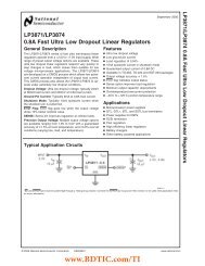
TYPICAL CIRCUIT CONNECTION<br />
A bus-powered (Hi-power), +20-dB microphone amplifier application example is shown in Figure 37.<br />
REC<br />
R12<br />
C17<br />
Mic Mute<br />
R13<br />
POWER 24 23 22 21 20 19 18 17 MBIAS<br />
PLAY<br />
25<br />
26<br />
27<br />
28<br />
29<br />
30<br />
31<br />
32<br />
PGND<br />
V CCP<br />
TEST1<br />
TEST0<br />
SSPND<br />
MMUTE<br />
REC<br />
PLAY<br />
C14<br />
BGND 1 2 3 4 5 6 7 8<br />
R1 R2<br />
Headphone<br />
R11<br />
R10<br />
PCM2912A<br />
V BUS D– D+ GND<br />
C1<br />
R8<br />
R7<br />
C11<br />
C2<br />
V IN<br />
V CCA<br />
NC<br />
AGND<br />
V COM2<br />
FR<br />
FL<br />
R4<br />
X1<br />
C3<br />
<strong>USB</strong> Connector<br />
16<br />
15<br />
14<br />
13<br />
12<br />
11<br />
10<br />
9<br />
Microphone<br />
NOTE: X 1: 6-MHz crystal resonator<br />
C 1, C 8, C 11, C 14, C 17, C 18: 1 μF ceramic<br />
C 2, C 3: 10 pF to 33 pF (depending on load capacitance of crystal resonator)<br />
C 4, C 5: 100 pF ceramic<br />
C 6, C 10: 3.3 μF<br />
C 7: 0.1 μF<br />
C 9: 0.22 μF electrolytic (depending on required frequency response for microphone input)<br />
C 13, C 16: 100 μF electrolytic (depending on required frequency response for headphone output)<br />
R 1, R 2: 22 Ω to 33 Ω<br />
R 3: 1.5 kΩ<br />
R 4: 1 MΩ<br />
R 5: 1 kΩ (depending on microphone characteristic)<br />
R 7, R 8, R 10, R 11: 3.3 kΩ<br />
R 12, R 13: 820 Ω (depending on LED drive current)<br />
L 1: 1 μH (DC resistance < 0.6 Ω)<br />
It is possible to change maximum power if total power of actual application does not require over 100 mA (set<br />
POWER = low to configure as low-power device).<br />
C18<br />
L1<br />
C16<br />
MAMP<br />
V BUS<br />
V R<br />
OUT<br />
D-<br />
V CC R<br />
D+<br />
R3<br />
HGND<br />
VCCL V DD<br />
DGND<br />
V L<br />
OUT<br />
XTO<br />
C13<br />
XTI<br />
R5<br />
C10<br />
V COM1<br />
Figure 37. <strong>USB</strong> Headset Application<br />
NOTE:<br />
The circuit in Figure 37 is for information only. Total board design should be<br />
considered in order to meet the <strong>USB</strong> specification as a <strong>USB</strong>-compliant product.<br />
26 Submit Documentation Feedback Copyright © 2008, <strong>Texas</strong> <strong>Instruments</strong> Incorporated<br />
Product Folder Link(s): PCM2912A<br />
C9<br />
C8<br />
C7<br />
C6<br />
C5<br />
C4
RELATED DOCUMENTATION FROM TEXAS INSTRUMENTS<br />
PCM2912A<br />
www.ti.com.......................................................................................................................................................................................... SLES230–SEPTEMBER 2008<br />
For additional information concerning the PCM2912A device, see the TI application report, Operating<br />
Envronments for PCM2912 Applications (SLAA387), available for download from www.ti.com.<br />
Copyright © 2008, <strong>Texas</strong> <strong>Instruments</strong> Incorporated Submit Documentation Feedback 27<br />
Product Folder Link(s): PCM2912A
PACKAGING INFORMATION<br />
Orderable Device Status (1)<br />
Package<br />
Type<br />
Package<br />
Drawing<br />
Pins Package<br />
Qty<br />
PCM2912APJT ACTIVE TQFP PJT 32 250 Green (RoHS &<br />
no Sb/Br)<br />
PCM2912APJTR ACTIVE TQFP PJT 32 1000 Green (RoHS &<br />
no Sb/Br)<br />
Eco Plan (2) Lead/Ball Finish MSL Peak Temp (3)<br />
CU NIPDAU Level-1-260C-UNLIM<br />
CU NIPDAU Level-1-260C-UNLIM<br />
(1) The marketing status values are defined as follows:<br />
ACTIVE: Product device recommended for new designs.<br />
LIFEBUY: TI has announced that the device will be discontinued, and a lifetime-buy period is in effect.<br />
NRND: Not recommended for new designs. Device is in production to support existing customers, but TI does not recommend using this part in<br />
a new design.<br />
PREVIEW: Device has been announced but is not in production. Samples may or may not be available.<br />
OBSOLETE: TI has discontinued the production of the device.<br />
(2) Eco Plan - The planned eco-friendly classification: Pb-Free (RoHS), Pb-Free (RoHS Exempt), or Green (RoHS & no Sb/Br) - please check<br />
http://www.ti.com/productcontent for the latest availability information and additional product content details.<br />
TBD: The Pb-Free/Green conversion plan has not been defined.<br />
Pb-Free (RoHS): TI's terms "Lead-Free" or "Pb-Free" mean semiconductor products that are compatible <strong>with</strong> the current RoHS requirements<br />
for all 6 substances, including the requirement that lead not exceed 0.1% by weight in homogeneous materials. Where designed to be soldered<br />
at high temperatures, TI Pb-Free products are suitable for use in specified lead-free processes.<br />
Pb-Free (RoHS Exempt): This component has a RoHS exemption for either 1) lead-based flip-chip solder bumps used between the die and<br />
package, or 2) lead-based die adhesive used between the die and leadframe. The component is otherwise considered Pb-Free (RoHS<br />
compatible) as defined above.<br />
Green (RoHS & no Sb/Br): TI defines "Green" to mean Pb-Free (RoHS compatible), and free of Bromine (Br) and Antimony (Sb) based flame<br />
retardants (Br or Sb do not exceed 0.1% by weight in homogeneous material)<br />
(3) MSL, Peak Temp. -- The Moisture Sensitivity Level rating according to the JEDEC industry standard classifications, and peak solder<br />
temperature.<br />
PACKAGE OPTION ADDENDUM<br />
www.ti.com 22-Nov-2008<br />
Important Information and Disclaimer:The information provided on this page represents TI's knowledge and belief as of the date that it is<br />
provided. TI bases its knowledge and belief on information provided by third parties, and makes no representation or warranty as to the<br />
accuracy of such information. Efforts are underway to better integrate information from third parties. TI has taken and continues to take<br />
reasonable steps to provide representative and accurate information but may not have conducted destructive testing or chemical analysis on<br />
incoming materials and chemicals. TI and TI suppliers consider certain information to be proprietary, and thus CAS numbers and other limited<br />
information may not be available for release.<br />
In no event shall TI's liability arising out of such information exceed the total purchase price of the TI part(s) at issue in this document sold by TI<br />
to Customer on an annual basis.<br />
Addendum-Page 1
TAPE AND REEL INFORMATION<br />
*All dimensions are nominal<br />
Device Package<br />
Type<br />
Package<br />
Drawing<br />
Pins SPQ Reel Reel<br />
Diameter Width<br />
(mm) W1 (mm)<br />
PACKAGE MATERIALS INFORMATION<br />
www.ti.com 5-Dec-2008<br />
A0 (mm) B0 (mm) K0 (mm) P1<br />
(mm)<br />
PCM2912APJTR TQFP PJT 32 1000 330.0 16.4 9.6 9.6 1.5 12.0 16.0 Q2<br />
Pack Materials-Page 1<br />
W<br />
(mm)<br />
Pin1<br />
Quadrant
*All dimensions are nominal<br />
PACKAGE MATERIALS INFORMATION<br />
www.ti.com 5-Dec-2008<br />
Device Package Type Package Drawing Pins SPQ Length (mm) Width (mm) Height (mm)<br />
PCM2912APJTR TQFP PJT 32 1000 346.0 346.0 33.0<br />
Pack Materials-Page 2
POST OFFICE BOX 655303 • DALLAS, TEXAS 75265<br />
MECHANICAL DATA<br />
MPQF112 – NOVEMBER 2001<br />
PJT (S-PQFP–N32) PLASTIC QUAD FLATPACK<br />
1,05<br />
0,95<br />
32<br />
0,80<br />
0,45<br />
0,20 M<br />
0,30<br />
1<br />
7,00 SQ<br />
9,00<br />
Seating Plane<br />
1,20 0,10<br />
1,00<br />
SQ<br />
NOTES: A. All linear dimensions are in millimeters.<br />
B. This drawing is subject to change <strong>with</strong>out notice.<br />
C. Falls <strong>with</strong>in JEDEC MS-026<br />
0,15<br />
0,05<br />
0,25<br />
0,75<br />
0,45<br />
Gage Plane<br />
0°– 7°<br />
0,20<br />
0,09<br />
4203540/A 11/01<br />
1
IMPORTANT NOTICE<br />
<strong>Texas</strong> <strong>Instruments</strong> Incorporated and its subsidiaries (TI) reserve the right to make corrections, modifications, enhancements, improvements,<br />
and other changes to its products and services at any time and to discontinue any product or service <strong>with</strong>out notice. Customers should<br />
obtain the latest relevant information before placing orders and should verify that such information is current and complete. All products are<br />
sold subject to TI’s terms and conditions of sale supplied at the time of order acknowledgment.<br />
TI warrants performance of its hardware products to the specifications applicable at the time of sale in accordance <strong>with</strong> TI’s standard<br />
warranty. Testing and other quality control techniques are used to the extent TI deems necessary to support this warranty. Except where<br />
mandated by government requirements, testing of all parameters of each product is not necessarily performed.<br />
TI assumes no liability for applications assistance or customer product design. Customers are responsible for their products and<br />
applications using TI components. To minimize the risks associated <strong>with</strong> customer products and applications, customers should provide<br />
adequate design and operating safeguards.<br />
TI does not warrant or represent that any license, either express or implied, is granted under any TI patent right, copyright, mask work right,<br />
or other TI intellectual property right relating to any combination, machine, or process in which TI products or services are used. Information<br />
published by TI regarding third-party products or services does not constitute a license from TI to use such products or services or a<br />
warranty or endorsement thereof. Use of such information may require a license from a third party under the patents or other intellectual<br />
property of the third party, or a license from TI under the patents or other intellectual property of TI.<br />
Reproduction of TI information in TI data books or data sheets is permissible only if reproduction is <strong>with</strong>out alteration and is accompanied<br />
by all associated warranties, conditions, limitations, and notices. Reproduction of this information <strong>with</strong> alteration is an unfair and deceptive<br />
business practice. TI is not responsible or liable for such altered documentation. Information of third parties may be subject to additional<br />
restrictions.<br />
Resale of TI products or services <strong>with</strong> statements different from or beyond the parameters stated by TI for that product or service voids all<br />
express and any implied warranties for the associated TI product or service and is an unfair and deceptive business practice. TI is not<br />
responsible or liable for any such statements.<br />
TI products are not authorized for use in safety-critical applications (such as life support) where a failure of the TI product would reasonably<br />
be expected to cause severe personal injury or death, unless officers of the parties have executed an agreement specifically governing<br />
such use. Buyers represent that they have all necessary expertise in the safety and regulatory ramifications of their applications, and<br />
acknowledge and agree that they are solely responsible for all legal, regulatory and safety-related requirements concerning their products<br />
and any use of TI products in such safety-critical applications, not<strong>with</strong>standing any applications-related information or support that may be<br />
provided by TI. Further, Buyers must fully indemnify TI and its representatives against any damages arising out of the use of TI products in<br />
such safety-critical applications.<br />
TI products are neither designed nor intended for use in military/aerospace applications or environments unless the TI products are<br />
specifically designated by TI as military-grade or "enhanced plastic." Only products designated by TI as military-grade meet military<br />
specifications. Buyers acknowledge and agree that any such use of TI products which TI has not designated as military-grade is solely at<br />
the Buyer's risk, and that they are solely responsible for compliance <strong>with</strong> all legal and regulatory requirements in connection <strong>with</strong> such use.<br />
TI products are neither designed nor intended for use in automotive applications or environments unless the specific TI products are<br />
designated by TI as compliant <strong>with</strong> ISO/TS 16949 requirements. Buyers acknowledge and agree that, if they use any non-designated<br />
products in automotive applications, TI will not be responsible for any failure to meet such requirements.<br />
Following are URLs where you can obtain information on other <strong>Texas</strong> <strong>Instruments</strong> products and application solutions:<br />
Products Applications<br />
Amplifiers amplifier.ti.com <strong>Audio</strong> www.ti.com/audio<br />
Data Converters dataconverter.ti.com Automotive www.ti.com/automotive<br />
DSP dsp.ti.com Broadband www.ti.com/broadband<br />
Clocks and Timers www.ti.com/clocks Digital Control www.ti.com/digitalcontrol<br />
<strong>Interface</strong> interface.ti.com Medical www.ti.com/medical<br />
Logic logic.ti.com Military www.ti.com/military<br />
Power Mgmt power.ti.com Optical Networking www.ti.com/opticalnetwork<br />
Microcontrollers microcontroller.ti.com Security www.ti.com/security<br />
RFID www.ti-rfid.com Telephony www.ti.com/telephony<br />
RF/IF and ZigBee® Solutions www.ti.com/lprf Video & Imaging www.ti.com/video<br />
Wireless www.ti.com/wireless<br />
Mailing Address: <strong>Texas</strong> <strong>Instruments</strong>, Post Office Box 655303, Dallas, <strong>Texas</strong> 75265<br />
Copyright © 2008, <strong>Texas</strong> <strong>Instruments</strong> Incorporated