M085 M086 Converter P-Bus / Modbus RS485 - Domat International
M085 M086 Converter P-Bus / Modbus RS485 - Domat International
M085 M086 Converter P-Bus / Modbus RS485 - Domat International

Create successful ePaper yourself
Turn your PDF publications into a flip-book with our unique Google optimized e-Paper software.
<strong>M085</strong><br />
<strong>M086</strong><br />
<strong>Converter</strong> P-<strong>Bus</strong> / <strong>Modbus</strong> <strong>RS485</strong><br />
Summary<br />
<strong>M085</strong> and <strong>M086</strong> are microprocessor-controlled converters of Landis & Gyr P-<strong>Bus</strong><br />
for I/O modules Landis & Gyr PTM..., PTK... to <strong>Modbus</strong> RTU over <strong>RS485</strong>. The<br />
converters provide galvanical separation of both interfaces and the power part,<br />
and they are able to supply 32 or 64 BE (P-<strong>Bus</strong> load units) respectively.<br />
Application<br />
<br />
integration of Landis & Gyr I/O modules into a SoftPLC or 3 rd party<br />
environment – reconstruction and refurbishment of old plants using<br />
Landis & Gyr PRU.., PRV.., and RWP80 controllers.<br />
Function<br />
The converter links the I/O modules of total load of up to 64 BE to <strong>Domat</strong> MiniPLC,<br />
<strong>Domat</strong> IPLC500, IPLC510, IPCB.1, IPCT.1, to a SoftPLC runtime or to any other client<br />
capable of <strong>Modbus</strong> RTU communication.<br />
After powering on, the converter continuously scans the P-<strong>Bus</strong> and searches for the<br />
connected I/O modules which updates the internal I/O list. Using special commands<br />
(over domat.exe or according to the <strong>Modbus</strong> table) it is possible to save the actual<br />
configuration of the P-<strong>Bus</strong> (addresses and types of the I/O modules) into the memory of<br />
the converter, which speeds up the P-<strong>Bus</strong> communication. This is recommended<br />
especially at higher <strong>Modbus</strong> baudrates.<br />
Technical data<br />
Power supply<br />
Consumption<br />
universal 90...260 V AC, 120...370 V DC<br />
according to P-<strong>Bus</strong> load units, max. 30 VA<br />
Fuse<br />
Ambient temperature 0 ÷ 50°C<br />
Ambient humidity<br />
Output P-<strong>Bus</strong> PWR<br />
Max. current<br />
Short-circuit protection<br />
<strong>RS485</strong> communication<br />
Maximum bus length<br />
replaceable fuse T2A / 250 V<br />
5% ÷ 95% non-condensing<br />
24 V AC<br />
<strong>M085</strong>: 0.6 A, <strong>M086</strong>: 1.0 A<br />
Automatic fuse against overload, shortcircuit,<br />
overvoltage with automatic reset<br />
1200 m<br />
domat <strong>M085</strong> 1
Max. number of devices on the bus 256<br />
Baud rate<br />
Protocol<br />
<strong>Modbus</strong> addressing<br />
P-<strong>Bus</strong> communication<br />
Load<br />
Galvanical separation<br />
Dimensions<br />
1200...115200 bps<br />
<strong>Modbus</strong> RTU slave<br />
with free software: domat.exe or SoftPLC IDE<br />
Permanently short-circuit resistant<br />
<strong>M085</strong>: 32 BE, <strong>M086</strong>: 64 BE<br />
power supply part, <strong>RS485</strong>, and P-<strong>Bus</strong> are<br />
mutually optically separated up to 1000 V DC<br />
see below<br />
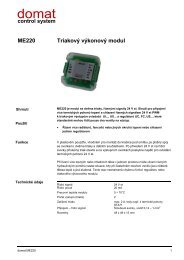
Terminals, LED<br />
Connection<br />
T2A / 250V L N TE<br />
<strong>M085</strong><br />
PWR<br />
TXD<br />
PBUS<br />
ON<br />
P-BUS PWR<br />
PU GND<br />
1 2<br />
INIT<br />
PBUS<br />
PWR<br />
ON<br />
1 2<br />
BUS<br />
END<br />
<strong>RS485</strong><br />
K+ K-<br />
P-BUS COM<br />
PC PU PD<br />
T2A/250V<br />
L<br />
N<br />
TE<br />
PWR<br />
TXD<br />
PBUS<br />
INIT<br />
BUS END<br />
<strong>RS485</strong> K+<br />
<strong>RS485</strong> K-<br />
fuse<br />
power, 230 V phase<br />
power, reference<br />
technical earth (optional)<br />
on: power OK<br />
<strong>RS485</strong> data transmit, red<br />
on: communication error<br />
flashes 1:1 : communication OK<br />
flashes 1:8 : communication off<br />
if ON at power-up, <strong>RS485</strong> default<br />
communication parameters (adr.<br />
1, 9600 bps, N, 8, 1) are set<br />
both switches at ON: <strong>RS485</strong><br />
termination<br />
communication, positive<br />
communication, negative<br />
PU P-<strong>Bus</strong> power, +<br />
GND<br />
P-<strong>Bus</strong> power ground<br />
PBUS PWR on: P-<strong>Bus</strong> power OK<br />
PC<br />
P-<strong>Bus</strong> time sync<br />
PU<br />
reference voltage<br />
PD<br />
P-<strong>Bus</strong> data<br />
230 V AC<br />
<strong>Modbus</strong> RTU<br />
L N TE K+ K-<br />
<strong>M085</strong>, <strong>M086</strong><br />
PU GND PC PU PD<br />
24 V ~ G G0<br />
PC PU PD<br />
Tr1<br />
L&G PTM..., PTK....<br />
Tr1... original transformer for<br />
powering of the I/O modules<br />
2 domat <strong>M085</strong>
The power supply 24 V of the <strong>M085</strong>, <strong>M086</strong> (P-BUS PWR, terminals PU a GND) may be<br />
used e.g. as a power source for a process station (IPLC) etc, but only up to the load<br />
limit of 0.6 A (<strong>M085</strong>) or 1 A (<strong>M086</strong>).<br />
Installation<br />
Maintenance<br />
The converter is snapped on a DIN rail. Remember to leave space enough around the<br />
device to allow heat dissipation.<br />
If the PWR LED is off, please check / replace the fuse. Use only fuse of the same type<br />
and rating!<br />
Dimensions<br />
14<br />
8,5<br />
90<br />
45<br />
8,5<br />
14<br />
21,5<br />
53<br />
105 58<br />
10<br />
Related products<br />
IPLC500<br />
IPLC510<br />
IPCT.1<br />
IPCB.1<br />
M012<br />
M080<br />
M035<br />
RC-Vision<br />
MiniPLC process station<br />
MiniPLC process station<br />
process station with touchscreen<br />
process station without touchscreen<br />
converter RS232-<strong>RS485</strong><br />
converter USB-<strong>RS485</strong><br />
<strong>Modbus</strong> RTU / TCP router<br />
SCADA software<br />
03/2012 Subject to technical changes.<br />
domat <strong>M085</strong> 3
Attachment 1: The <strong>Modbus</strong> table<br />
The following <strong>Modbus</strong> functions are supported:<br />
F01 Read Coil Status – reading bits<br />
F03 Read Holding Registers – reading words<br />
F15 Force Multiple Coils – writing bits<br />
F16 Force Multiple Registers – writing words.<br />
Register name<br />
module ID<br />
firmware<br />
status LSB<br />
Register<br />
number<br />
1 LSB<br />
1 MSB<br />
2 LSB<br />
2 MSB<br />
3 LSB<br />
3 MSB<br />
Type Description Note<br />
R module identification at <strong>RS485</strong> 2-byte number, here 0x0091<br />
R firmware version 0x0100 = V1.00<br />
R, W RAM module status lower byte<br />
bit 0 – EEPROM write enabled<br />
bit 1 – P-<strong>Bus</strong> comm. stop<br />
bit 2 – P-<strong>Bus</strong> config reset<br />
bit 3 – Pbus config save<br />
bit 4 – EEPROM init (not used)<br />
bit 5 – P-<strong>Bus</strong> module search stop<br />
EEPROM init<br />
Proceed as follows:<br />
- set the INIT switch to ON<br />
- power the module on<br />
- set the INIT switch to OFF<br />
- set bit 4 to 1<br />
(indicated by bit 2 in status<br />
MSB)<br />
EEPROM init : init switch on, start<br />
module, init switch off, set bit 4 to 1<br />
(indicated by bit 2 in status MSB)<br />
status MSB 3 MSB R RAM bit 1 – init mode active (INIT switch is<br />
ON)<br />
bit 2 – EEPROM write enabled<br />
bit 3 – EEPROM inited (not used)<br />
baud rate<br />
(communication<br />
speed)<br />
<strong>Modbus</strong> address 4 MSB<br />
4 LSB R, W<br />
EEPROM<br />
R, W<br />
EEPROM<br />
bit 5 – P-<strong>Bus</strong> comm error<br />
10dec … 1200 bps<br />
New baudrate setting is active<br />
11dec … 2400 bps<br />
only after restart. The register<br />
12dec … 4800 bps<br />
is written immediately.<br />
13dec … 9600 bps (výchozí hodnota)<br />
14dec … 19200 bps<br />
15dec … 38400 bps<br />
16dec … 57600 bps<br />
17dec … 115200 bps<br />
1...250 default address: 1<br />
reserved<br />
5 LSB<br />
serial <strong>RS485</strong> port5 MSB R, W<br />
settings<br />
EEPROM<br />
parameters of the <strong>RS485</strong><br />
communication<br />
(default = no partiy, one stop bit:<br />
0x00)<br />
bit 0-1 ... parity<br />
(00 –no parity, 01 – even, 10 –<br />
odd)<br />
bit 2 ... stop bits (0 – one, 1 -<br />
two)<br />
number of found 6 LSB<br />
modules 6 MSB<br />
number of 7 LSB<br />
definitions of 7 MSB<br />
known modules<br />
R<br />
R<br />
number of I/O modules found on the<br />
P-<strong>Bus</strong><br />
number of I/O module types in the<br />
internal library (may differ with<br />
firmware versions)<br />
New settings is active only after<br />
restart. The register is written<br />
immediately.<br />
for diagnostics only<br />
for diagnostics only<br />
4 domat <strong>M085</strong>
uptime<br />
8 LSB<br />
8 MSB<br />
R uptime in ticks for diagnostics only<br />
module data<br />
1001 LSB R, W RAM Data of the P-<strong>Bus</strong> module with<br />
1001 MSB<br />
address 0, register 0<br />
module data 1002 LSB<br />
1002 MSB<br />
R, W RAM Data of the P-<strong>Bus</strong> module with<br />
address 0, register 1<br />
module data 1003 LSB<br />
1003 MSB<br />
R, W RAM Data of the P-<strong>Bus</strong> module with<br />
address 0, register 2<br />
module data 1004 LSB<br />
1004 MSB<br />
R, W RAM Data of the P-<strong>Bus</strong> module with<br />
address 0, register 3<br />
module data 1005 LSB<br />
1005 MSB<br />
R, W RAM Data of the P-<strong>Bus</strong> module with<br />
address 1, register 0<br />
...<br />
module data 1008 LSB<br />
1008 MSB<br />
R, W RAM Data of the P-<strong>Bus</strong> module with<br />
address 1, register 3<br />
... (other modules and their registers)<br />
module data 1512 LSB<br />
1512 MSB<br />
R, W RAM Data of the P-<strong>Bus</strong> module with<br />
address 127, register 3<br />
module info 2001 LSB<br />
2001 MSB<br />
R RAM P-<strong>Bus</strong> module address 0,<br />
P-<strong>Bus</strong> address<br />
module info 2002 LSB<br />
2002 MSB<br />
R RAM P-<strong>Bus</strong> module address 0,<br />
module status<br />
module info 2003 LSB R RAM P-<strong>Bus</strong> module address 0,<br />
2003 MSB<br />
module type (code see below)<br />
module info 2004 LSB R RAM P-<strong>Bus</strong> module address 0,<br />
2004 MSB<br />
detected module type (code see<br />
below)<br />
module info 2005 LSB R RAM P-<strong>Bus</strong> module address 1,<br />
2005 MSB<br />
P-<strong>Bus</strong> address<br />
... (other modules and their states)<br />
module info 2512 LSB R RAM P-<strong>Bus</strong> module address 127,<br />
2512 MSB<br />
detected module type (code see<br />
below)<br />
To be interpreted according to<br />
the I/O module type, see tables<br />
below<br />
bit 0: comm error<br />
bit 15: read from Flash<br />
For commissioning, SoftPLC IDE and a converter RS232 or USB to <strong>RS485</strong> are used.<br />
Define a serial channel in the SoftPLC IDE, and insert the Landis & Gyr P-<strong>Bus</strong> I/O<br />
modules into the channel according to the module types and address pegs. The <strong>M085</strong><br />
or <strong>M086</strong> is to be addressed in the Special functions menu (it may be connected on the<br />
<strong>RS485</strong> bus together with more <strong>Modbus</strong>/<strong>RS485</strong> modules if the data throughput is OK)<br />
and after the communication from the SoftPLC is started, the module starts to<br />
communicate with the P-<strong>Bus</strong> I/O modules. It is not necessary to use the <strong>Modbus</strong> table.<br />
When communicating with other / 3 rd Party clients, use <strong>Modbus</strong> registers 1001 and<br />
higher for communication with the converter. In the registers of 2001 and higher, there<br />
are diagnostic data: types and states of the P-<strong>Bus</strong> modules which were auto-detected<br />
by the converter.<br />
domat <strong>M085</strong> 5
Attachment 2: Variable maps for P-<strong>Bus</strong> I/O modules<br />
The address of the first register (Register 0) with the module data is 1000 + 4 * P-<strong>Bus</strong><br />
address (peg), see <strong>Modbus</strong> table. The module is represented by maximum 4 registers.<br />
Example: Input 2 (Register 1, see below) of the module PTM1.2R1K (2x passive AI) with<br />
the address peg No. 3 is to be read in the register with address of<br />
1000 + 4 * 3 + 1 = 1013.<br />
PTM1.2C<br />
2x pulse counter<br />
Module code 0x0000<br />
Register 0 (read)<br />
Bit Description<br />
0 Pulse input 2 bit 0<br />
1 Pulse input 2 bit 1<br />
2 Pulse input 2 bit 2<br />
3 Pulse input 2 bit 3<br />
4 Pulse input 2 bit 4<br />
5 Pulse input 2 bit 5<br />
6 Pulse input 2 bit 6<br />
7 No function<br />
8 Pulse input 1 bit 0<br />
9 Pulse input 1 bit 1<br />
10 Pulse input 1 bit 2<br />
11 Pulse input 1 bit 3<br />
12 Pulse input 1 bit 4<br />
13 Pulse input 1 bit 5<br />
14 Pulse input 1 bit 6<br />
15 No function<br />
PTM1.2D20<br />
2x potential-free digital input<br />
Module code 0x0101<br />
Register 0 (read)<br />
Bit Description<br />
0 Input 1 (0 – off, 1 – on)<br />
1 Input 2 (0 – off, 1 – on)<br />
2 No function<br />
3 No function<br />
4 No function<br />
5 No function<br />
6 No function<br />
7 No function<br />
8 Input 1 (0 – off, 1 – on)<br />
9 Input 2 (0 – off, 1 – on)<br />
10 No function<br />
11 No function<br />
12 No function<br />
13 No function<br />
14 No function<br />
15 No function<br />
6 domat <strong>M085</strong>
PTM1.2R1K<br />
2x analog passive input for Ni1000 L&G sensors<br />
Module code 0x0202<br />
Register 0 (read, Input 1), Register 1 (read, Input 2)<br />
Bit Description<br />
0 No function<br />
1 No function<br />
2 No function<br />
3 A/D converter, bit 0<br />
4 A/D converter, bit 1<br />
5 A/D converter, bit 2<br />
6 A/D converter, bit 3<br />
7 A/D converter, bit 4<br />
8 A/D converter, bit 5<br />
9 A/D converter, bit 6<br />
10 A/D converter, bit 7<br />
11 A/D converter, bit 8<br />
12 A/D converter, bit 9<br />
13 A/D converter, bit 10<br />
14 A/D converter, bit 11<br />
15 Broken or short-circuit<br />
The converter has 12 bit resolution (0...4095). The curve is linearised in the module. The<br />
temperature is calculated from the read value X :<br />
t = 0.05 * X – 52.4<br />
so e.g. for the read value of 1448 the temperature is t = 0.05 * 1448 – 52.4 = 20 °C.<br />
Bit 15 in true indicates a broken or short-circuited sensor. The measured value range is<br />
–50...150 °C (read value 48...4048). Broken sensor: the read value is 4095, short<br />
circuited sensor: 0.<br />
PTM1.2Y10<br />
2x analog output 0...10 V<br />
Module code 0x0303<br />
Register 0 (write, Output 1), Register 1 (write, Output 2)<br />
Bit Description<br />
0 Back-up value, bit 0<br />
1 Back-up value, bit 1<br />
2 Back-up value, bit 2<br />
3 Back-up value, bit 3<br />
4 Back-up value, bit 4<br />
5 No function<br />
6 No function<br />
7 D/A converter, bit 0<br />
8 D/A converter, bit 1<br />
9 D/A converter, bit 2<br />
10 D/A converter, bit 3<br />
11 D/A converter, bit 4<br />
12 D/A converter, bit 5<br />
13 D/A converter, bit 6<br />
14 D/A converter, bit 7<br />
15 No function<br />
domat <strong>M085</strong> 7
The converter has 8 bit resolution (0...240 dec), which corresponds to the output of 0..10<br />
V (0...100 %).<br />
The back-up value has 5 bit resolution, 0...31 dec, which corresponds to the output of<br />
0..10 V (0...100 %). If the P-<strong>Bus</strong> is not communicating, i.e. the I/O module does not<br />
receive a valid telegram at least each 4 s, the output is set to the backup value.<br />
PTM1.2U10<br />
2x analog input 0...10 V<br />
Module code 0x0606<br />
Register 0 (read, Input 1), Register 1 (read, Input 2)<br />
Bit Description<br />
0 No function<br />
1 No function<br />
2 A/D converter, bit 0<br />
3 A/D converter, bit 1<br />
4 A/D converter, bit 2<br />
5 A/D converter, bit 3<br />
6 A/D converter, bit 4<br />
7 A/D converter, bit 5<br />
8 A/D converter, bit 6<br />
9 A/D converter, bit 7<br />
10 A/D converter, bit 8<br />
11 A/D converter, bit 9<br />
12 A/D converter, bit 10<br />
13 A/D converter, bit 11<br />
14 A/D converter, bit 12<br />
15 No function<br />
The converter has 13 bit resolution (0...8191). The measured value Y is calculated from<br />
the read value X:<br />
Y = 0.03125 * (X / 2) – 14.0<br />
so e.g. for a humidity sensor and the read value of 7296 the rH = 0.03125 * (7296 / 2) –<br />
14.0 = 100 %rH.<br />
The measured value range is 0...10 V (read value 896...7296). A value < 64 means<br />
underflow, a value > 8126 is overflow.<br />
PTM1.2Y10S-M<br />
2x analog output 0...10 V with manual override<br />
Module code 0x0303<br />
Register 0 (write, Output 1), Register 1 (write, Output 2)<br />
Bit Description<br />
0 Back-up value, bit 0<br />
1 Back-up value, bit 1<br />
2 Back-up value, bit 2<br />
3 Back-up value, bit 3<br />
4 Back-up value, bit 4<br />
5 No function<br />
6 No function<br />
7 D/A converter, bit 0<br />
8 D/A converter, bit 1<br />
9 D/A converter, bit 2<br />
10 D/A converter, bit 3<br />
11 D/A converter, bit 4<br />
12 D/A converter, bit 5<br />
8 domat <strong>M085</strong>
13 D/A converter, bit 6<br />
14 D/A converter, bit 7<br />
15 No function<br />
Register 3 (read)<br />
Bit Description<br />
0 Output 1 in manual mode (1 = active)<br />
1 Output 2 in manual mode (1 = active)<br />
2 No function<br />
3 No function<br />
4 No function<br />
5 No function<br />
6 No function<br />
7 No function<br />
8 Manual override status Output 1 (1 = on, 0 = off)<br />
9 Manual override status Output 2 (1 = on, 0 = off)<br />
10 No function<br />
11 No function<br />
12 No function<br />
13 No function<br />
14 No function<br />
15 No function<br />
The converter has 8 bit resolution (0...240 dec), which corresponds to the output of 0..10<br />
V (0...100 %).<br />
The back-up value has 5 bit resolution, 0...31 dec, which corresponds to the output of<br />
0..10 V (0...100 %). If the P-<strong>Bus</strong> is not communicating, i.e. the I/O module does not<br />
receive a valid telegram at least each 4 s, the output is set to the backup value.<br />
PTM1.2QD<br />
Relay output 250 V AC with operation feedback<br />
Module code 0x0909<br />
Register 0 (write)<br />
Bit Description<br />
0 No function<br />
1 No function<br />
2 No function<br />
3 No function<br />
4 No function<br />
5 No function<br />
6 No function<br />
7 No function<br />
8 No function<br />
9 No function<br />
10 No function<br />
11 No function<br />
12 No function<br />
13 No function<br />
14 No function<br />
15 Relay command (0 = off, 1 = on)<br />
Register 1 (read)<br />
Bit Description<br />
0 No function<br />
1 No function<br />
2 No function<br />
3 No function<br />
4 Operation (feedback)<br />
domat <strong>M085</strong> 9
5 No function<br />
6 No function<br />
7 No function<br />
8 No function<br />
9 No function<br />
10 No function<br />
11 No function<br />
12 No function<br />
13 No function<br />
14 No function<br />
15 Relay status from Register 0 (Write), bit 15<br />
PTM1.2P100<br />
2x analog passive input for sensors Pt100, Ni100 or potentiometer 0...250 Ohm<br />
Module code 0x0A0A<br />
Register 0 (read, Input 1), Register 1 (read, Input 2)<br />
Bit Description<br />
0 No function<br />
1 No function<br />
2 A/D converter, bit 0<br />
3 A/D converter, bit 1<br />
4 A/D converter, bit 2<br />
5 A/D converter, bit 3<br />
6 A/D converter, bit 4<br />
7 A/D converter, bit 5<br />
8 A/D converter, bit 6<br />
9 A/D converter, bit 7<br />
10 A/D converter, bit 8<br />
11 A/D converter, bit 9<br />
12 A/D converter, bit 10<br />
13 A/D converter, bit 11<br />
14 A/D converter, bit 12<br />
15 Broken or short-circuit<br />
The converter has 13 bit resolution (0...8191). The A/D converter output is linear. This<br />
means that for the Pt100 sensors the value must be linarized: either by an<br />
approximation of part of the curve which is considered linear, or in the PLC. With<br />
SoftPLC it is recommended to perform the interpolation in the variable properties.<br />
The measured value Y is calculated from the read value X:<br />
Y = S * (X/2) + O<br />
so e.g. for a Pt100 ranged 10...40 °C, where it is considered linear, and read value of<br />
3580, the temperature is t = 0.1718213 * (3580/2) -287.5085 = 20 °C.<br />
The measuring range is 0...250 Ohm (read value of 346...7846). The read value when<br />
overflow is >7920, when underflow it is
2 No function<br />
3 No function<br />
4 No function<br />
5 No function<br />
6 No function<br />
7 D/A converter, bit 0<br />
8 D/A converter, bit 1<br />
9 D/A converter, bit 2<br />
10 D/A converter, bit 3<br />
11 D/A converter, bit 4<br />
12 D/A converter, bit 5<br />
13 D/A converter, bit 6<br />
14 D/A converter, bit 7<br />
15 No function<br />
The converter has 8 bit resolution (0...240 dec), which corresponds to the output of<br />
4...20 mA (0...100 %).<br />
PTM1.2I25<br />
2x analog input 0...25 mA<br />
Module code 0x0E0E<br />
Register 0 (read, Input 1), Register 1 (read, Input 2)<br />
Bit Description<br />
0 No function<br />
1 No function<br />
2 A/D converter, bit 0<br />
3 A/D converter, bit 1<br />
4 A/D converter, bit 2<br />
5 A/D converter, bit 3<br />
6 A/D converter, bit 4<br />
7 A/D converter, bit 5<br />
8 A/D converter, bit 6<br />
9 A/D converter, bit 7<br />
10 A/D converter, bit 8<br />
11 A/D converter, bit 9<br />
12 A/D converter, bit 10<br />
13 A/D converter, bit 11<br />
14 A/D converter, bit 12<br />
15 No function<br />
Using shunts, following ranges may be selected:<br />
1 .. 5mA (200Ω); 0 .. 10mA (100Ω); 0(4) .. 20mA (50Ω) a 0 .. 25mA (40Ω). With no<br />
shunt the measuring range is voltage, 0...1 V DC.<br />
The converter has 13 bit resolution (0...8191). The measured value Y is calculated from<br />
the read value X:<br />
Y = S * (X/2) + O<br />
where X = read value, S = slope, O = offset, Y = measured value.<br />
Example: for a 0...20 mA sensor measuring 0...100 % rH, a 50 Ohm shunt and read<br />
value of 7296, the rH is<br />
rH = 0.03125 * (7296 / 2) – 14.0 = 100 %rH.<br />
The measured range is 0...25 mA (read value 896...7296). A value < 64 means<br />
underflow, a value > 8126 means overflow.<br />
domat <strong>M085</strong> 11
PTM1.4D20<br />
4x potential free digital input<br />
Module code 0x0111<br />
Register 0 (read)<br />
Bit Description<br />
0 Input 1 (0 – off, 1 – on)<br />
1 Input 2 (0 – off, 1 – on)<br />
2 Input 3 (0 – off, 1 – on)<br />
3 Input 4 (0 – off, 1 – on)<br />
4 No function<br />
5 No function<br />
6 No function<br />
7 No function<br />
8 Input 1 (0 – off, 1 – on)<br />
9 Input 2 (0 – off, 1 – on)<br />
10 Input 3 (0 – off, 1 – on)<br />
11 Input 4 (0 – off, 1 – on)<br />
12 No function<br />
13 No function<br />
14 No function<br />
15 No function<br />
PTM1.4Y10S<br />
4x analogue output 0...10 V<br />
Module code 0x1313<br />
Register 0 (write, Output 1), Register 1 (write, Output 2), Register 2 (write, Output<br />
3), Register 3 (write, Output 4)<br />
Bit Description<br />
0 Back-up value, bit 0<br />
1 Back-up value, bit 1<br />
2 Back-up value, bit 2<br />
3 Back-up value, bit 3<br />
4 Back-up value, bit 4<br />
5 No function<br />
6 No function<br />
7 D/A converter, bit 0<br />
8 D/A converter, bit 1<br />
9 D/A converter, bit 2<br />
10 D/A converter, bit 3<br />
11 D/A converter, bit 4<br />
12 D/A converter, bit 5<br />
13 D/A converter, bit 6<br />
14 D/A converter, bit 7<br />
15 No function<br />
The converter has 8 bit resolution (0...240 dec), which corresponds to the output of 0..10<br />
V (0...100 %).<br />
The back-up value has 5 bit resolution, 0...31 dec, which corresponds to the output of<br />
0..10 V (0...100 %). If the P-<strong>Bus</strong> is not communicating, i.e. the I/O module does not<br />
receive a valid telegram at least each 4 s, the output is set to the backup value.<br />
12 domat <strong>M085</strong>
PTM1.2P1K<br />
2x analog passive input for sensors Pt1000, Ni1000 or potentiometer 2500 Ohm<br />
Module code 0x1616<br />
Register 0 (read, Input 1), Register 1 (read, Input 2)<br />
Bit Description<br />
0 No function<br />
1 No function<br />
2 A/D converter, bit 0<br />
3 A/D converter, bit 1<br />
4 A/D converter, bit 2<br />
5 A/D converter, bit 3<br />
6 A/D converter, bit 4<br />
7 A/D converter, bit 5<br />
8 A/D converter, bit 6<br />
9 A/D converter, bit 7<br />
10 A/D converter, bit 8<br />
11 A/D converter, bit 9<br />
12 A/D converter, bit 10<br />
13 A/D converter, bit 11<br />
14 A/D converter, bit 12<br />
15 Broken or short-circuit<br />
The converter has 13 bit resolution (0...8191). The A/D converter output is linear. This<br />
means that for the Pt1000 sensors the value must be linarized: either by an<br />
approximation of part of the curve which is considered linear, or in the PLC. With<br />
SoftPLC it is recommended to perform the interpolation in the variable properties.<br />
The measured value Y is calculated from the read value X:<br />
Y = S * (X/2) + O<br />
so e.g. for a Pt1000 ranged 10...40 °C, where it is considered linear, and read value of<br />
3580, the temperature is t = 0.1718213 * (3580/2) -287.5085 = 20 °C.<br />
The measuring range is 0...2500 Ohm (read value of 346...7846). The read value when<br />
overflow is >7920, when underflow it is
13 No function<br />
14 Relay command Stage 2 (0 = Off, 1 = On)<br />
15 Relay command Stage 1 (0 = Off, 1 = On)<br />
Register 1 (read)<br />
Bit Description<br />
0 No function<br />
1 No function<br />
2 No function<br />
3 No function<br />
4 Operation (feedback) 1<br />
5 Operation (feedback) 2<br />
6 No function<br />
7 No function<br />
8 No function<br />
9 No function<br />
10 No function<br />
11 No function<br />
12 No function<br />
13 No function<br />
14 Relay status Stage 2 from Register 0 (Write, bit 14)<br />
15 Relay status Stage 1 from Register 0 (Write, bit 15)<br />
PTM1.2I420<br />
2x analogue input 4...20 mA<br />
Module code 0x1A1A<br />
Register 0 (read, Input 1), Register 1 (read, Input 2)<br />
Bit Description<br />
0 No function<br />
1 No function<br />
2 A/D converter, bit 0<br />
3 A/D converter, bit 1<br />
4 A/D converter, bit 2<br />
5 A/D converter, bit 3<br />
6 A/D converter, bit 4<br />
7 A/D converter, bit 5<br />
8 A/D converter, bit 6<br />
9 A/D converter, bit 7<br />
10 A/D converter, bit 8<br />
11 A/D converter, bit 9<br />
12 A/D converter, bit 10<br />
13 A/D converter, bit 11<br />
14 A/D converter, bit 12<br />
15 No function<br />
The converter has 13 bit resolution (0...8191). The measured value Y is calculated from<br />
the read value X:<br />
Y = S * (X/2) + O<br />
where X = read value, S = slope, O = offset, Y = measured value.<br />
Example: for a 0...20 mA sensor measuring 0...100 % rH, a 50 Ohm shunt and read<br />
value of 7296, the rH is<br />
rH = 0.03125 * (7296 / 2) – 14.0 = 100 %rH.<br />
The measured range is 4...20 mA (read value 896...7296). A value < 64 means<br />
underflow, a value > 8126 means overflow.<br />
14 domat <strong>M085</strong>
PTM1.2Q250<br />
2x relay output 24...250 V st<br />
Module code 0x1D1D<br />
Register 0 (write)<br />
Bit Description<br />
0 Relay command 1 (0 = Off, 1 = On)<br />
1 Relay command 2 (0 = Off, 1 = On)<br />
2 No function<br />
3 No function<br />
4 No function<br />
5 No function<br />
6 No function<br />
7 No function<br />
8 No function<br />
9 No function<br />
10 No function<br />
11 No function<br />
12 No function<br />
13 No function<br />
14 No function<br />
15 No function<br />
PTM1.4R1K<br />
4x analog passive input for sensors Ni1000 L&G<br />
Module code 0x1E1E<br />
Register 0 (read, Input 1), Register 1 (read, Input 2), Register 2 (read, Input 3),<br />
Register 3 (read, Input 4)<br />
Bit Description<br />
0 No function<br />
1 No function<br />
2 A/D converter, bit 0<br />
3 A/D converter, bit 1<br />
4 A/D converter, bit 2<br />
5 A/D converter, bit 3<br />
6 A/D converter, bit 4<br />
7 A/D converter, bit 5<br />
8 A/D converter, bit 6<br />
9 A/D converter, bit 7<br />
10 A/D converter, bit 8<br />
11 A/D converter, bit 9<br />
12 A/D converter, bit 10<br />
13 A/D converter, bit 11<br />
14 A/D converter, bit 12<br />
15 Broken or short-circuit<br />
The converter has 13 bit resolution (0...8191). The curve is linearised in the module. The<br />
temperature is calculated from the read value X :<br />
t = 0.05 * X – 52.4<br />
so e.g. for the read value of 2896 the temperature is t = 0.05 * 2896/2 – 52.4 = 20 °C.<br />
Bit 15 in true indicates a broken or short-circuited sensor. The measured value range is<br />
–50...150 °C (read value 96...8096). Broken sensor: the read value is 8091, short<br />
circuited sensor: 0.<br />
domat <strong>M085</strong> 15
PTM1.2Q250-M<br />
2x relay output 24...250 V AC with manual override<br />
Module code 0x2020<br />
Register 0 (write)<br />
Bit Description<br />
0 No function<br />
1 No function<br />
2 No function<br />
3 No function<br />
4 No function<br />
5 No function<br />
6 No function<br />
7 No function<br />
8 No function<br />
9 No function<br />
10 No function<br />
11 No function<br />
12 No function<br />
13 No function<br />
14 Relay command 2 (0 = Off, 1 = On)<br />
15 Relay command 1 (0 = Off, 1 = On)<br />
Register 1 (read)<br />
Bit Description<br />
0 Manual override of Output 1 active (1 = active)<br />
1 Manual override of Output 2 active (1 = active)<br />
2 No function<br />
3 No function<br />
4 No function<br />
5 No function<br />
6 No function<br />
7 No function<br />
8 Status of manual override Output 1 (inverted, 0=on, 1=off)<br />
9 Status of manual override Output 2 (inverted, 0=on, 1=off)<br />
10 No function<br />
11 No function<br />
12 No function<br />
13 No function<br />
14 Status of Relay 2 from Register 0 (Write), bit 14<br />
15 Status of Relay 1 from Register 0 (Write), bit 15<br />
PTM1.2D42<br />
2x low voltage digital input 24 V AC or 10...42 V DC<br />
Module code 0x2121<br />
Register 0 (read)<br />
Bit Description<br />
0 Input 1 (0 – no voltage, 1 – voltage applied)<br />
1 Input 2 (0 – no voltage, 1 – voltage applied)<br />
2 No function<br />
3 No function<br />
4 No function<br />
5 No function<br />
6 No function<br />
7 No function<br />
8 Input 1 (0 – no voltage, 1 – voltage applied)<br />
9 Input 2 (0 – no voltage, 1 – voltage applied)<br />
10 No function<br />
11 No function<br />
16 domat <strong>M085</strong>
12 No function<br />
13 No function<br />
14 No function<br />
15 No function<br />
PTM1.3Q-M3<br />
Three-stage relay output with manual override<br />
Module code 0x2828<br />
Register 0 (write)<br />
Bit Description<br />
0 No function<br />
1 No function<br />
2 No function<br />
3 No function<br />
4 No function<br />
5 No function<br />
6 No function<br />
7 No function<br />
8 No function<br />
9 No function<br />
10 No function<br />
11 No function<br />
12 No function<br />
13 Relay command 3 (0 = Off, 1 = On)<br />
14 Relay command 2 (0 = Off, 1 = On)<br />
15 Relay command 1 (0 = Off, 1 = On)<br />
Register 1 (read)<br />
Bit Description<br />
0 Manual override of the output active (1 = active)<br />
1 No function<br />
2 No function<br />
3 No function<br />
4 No function<br />
5 No function<br />
6 No function<br />
7 No function<br />
8 Status of manual override Output 1 (inverted, 0=on, 1=off)<br />
9 Status of manual override Output 2 (inverted, 0=on, 1=off)<br />
10 Status of manual override Output 3 (inverted, 0=on, 1=off)<br />
11 No function<br />
12 No function<br />
13 Status of Relay 3 from Register 0 (Write), bit 13<br />
14 Status of Relay 2 from Register 0 (Write), bit 14<br />
15 Status of Relay 1 from Register 0 (Write), bit 15<br />
PTM1.2D20S<br />
2x digital potential-free digital input with memory function<br />
Module code 0x2929<br />
Register 0 (read)<br />
Bit Description<br />
0 Input 1 (0 – pulse not detected, 1 – pulse detected)<br />
1 Input 2 (0 – pulse not detected, 1 – pulse detected)<br />
2 Stav ukládání – Input 1 (0 = reset, 1 = aktivní) – kopie reg. pro write 0 bit 2<br />
3 Stav ukládání – Input 2 (0 = reset, 1 = aktivní) – kopie reg. pro write 0 bit 3<br />
4 No function<br />
5 No function<br />
6 No function<br />
domat <strong>M085</strong> 17
7 No function<br />
8 Input 1 (0 – pulse not detected, 1 – pulse detected)<br />
9 Input 2 (0 – pulse not detected, 1 – pulse detected)<br />
10 Status storage function input 1 (Actual value write register 0 bit 2)<br />
11 Status storage function input 2 (Actual value write register 0 bit 3)<br />
12 No function<br />
13 No function<br />
14 No function<br />
15 No function<br />
Register 1 (write)<br />
Bit Description<br />
0 No function<br />
1 No function<br />
2 Storage function – Input 1 (0 = reset, 1 = active)<br />
3 Storage function – Input 2 (0 = reset, 1 = active)<br />
4 No function<br />
5 No function<br />
6 No function<br />
7 No function<br />
8 No function<br />
9 No function<br />
10 No function<br />
11 No function<br />
12 No function<br />
13 No function<br />
14 No function<br />
15 No function<br />
The storage function is activated by setting the write register 1 bit 2 for input 1<br />
or write register 1 bit 3 for input 2. After detection of a puls on the input read register 0<br />
bit 0 (input 1) or read register 0 bit 1 (input 2) is set. The input can now be processed by<br />
the automation controller.<br />
The read register 0 bit 0 or bit 1 remains set until the automation controller has<br />
reset the input by setting write register 1 bit 2 or 3 back to 0.<br />
The contact input can either be used for the detection of make or break contact<br />
pulses. However, detection of a puls is always indicated by a 1 in the<br />
corresponding read register 0 (bit 0 or 1).<br />
PTM1.2Q250-B<br />
2x bi-stable output with changeover contact 24...250 V AC<br />
Module code 0x2D2D<br />
Register 0 (write)<br />
Bit Description<br />
0 Relay 1 On command (1 = activation)<br />
1 Relay 1 Off command (1 = activation)<br />
2 Relay 2 On command (1 = activation)<br />
3 Relay 2 Off command (1 = activation)<br />
4 No function<br />
5 No function<br />
6 No function<br />
7 No function<br />
8 No function<br />
9 No function<br />
10 No function<br />
11 No function<br />
18 domat <strong>M085</strong>
12 No function<br />
13 No function<br />
14 No function<br />
15 No function<br />
Relay 1 states<br />
Command Bit 0 Bit 1<br />
No function 0 0<br />
On 1 0<br />
Off 0 1<br />
No function 1 1<br />
Relay 2 states<br />
Povel Bit 2 Bit 3<br />
No function 0 0<br />
On 1 0<br />
Off 0 1<br />
No function 1 1<br />
PTM1.4Q250-P<br />
4x relay output 24...250 V AC with manual override<br />
Module code 0x3030<br />
Register 0 (write)<br />
Bit Description<br />
0 No function<br />
1 No function<br />
2 No function<br />
3 No function<br />
4 No function<br />
5 No function<br />
6 No function<br />
7 No function<br />
8 No function<br />
9 No function<br />
10 No function<br />
11 No function<br />
12 Relay 4 command (0 = Off, 1 = On) – make contacts Q23 and Q24<br />
13 Relay 3 command (0 = Off, 1 = On) – break contacts Q21 and Q22<br />
14 Relay 2 command (0 = Off, 1 = On) – make contacts Q13 and Q14<br />
15 Relay 1 command (0 = Off, 1 = On) – break contacts Q11 and Q12<br />
Register 1 (read)<br />
Bit Description<br />
0 Manual override channel 1 (relay 1 and 2) active (1 = active)<br />
1 Manual override channel 2 (relay 3 relay 4) active (1 = active)<br />
2 No function<br />
3 No function<br />
4 No function<br />
5 No function<br />
6 No function<br />
7 No function<br />
8 No function<br />
9 No function<br />
10 No function<br />
11 No function<br />
12 Relay 4, value from Register 0, bit 12<br />
domat <strong>M085</strong> 19
13 Relay 3, value from Register 0, bit 13<br />
14 Relay 2, value from Register 0, bit 14<br />
15 Relay 1, value from Register 0, bit 15<br />
PTM1.2D250<br />
2x digital input for 24...250 V AC or 24...100 V DC<br />
Module code 0x3131<br />
Register 0 (read)<br />
Bit Description<br />
0 Input 1 (0 – voltage-free, 1 – voltage applied, LED on)<br />
1 Input 2 (0 – voltage-free, 1 – voltage applied, LED on)<br />
2 No function<br />
3 No function<br />
4 No function<br />
5 No function<br />
6 No function<br />
7 No function<br />
8 Input 1 (0 – voltage-free, 1 – voltage applied, LED on)<br />
9 Input 2 (0 – voltage-free, 1 – voltage applied, LED on)<br />
10 No function<br />
11 No function<br />
12 No function<br />
13 No function<br />
14 No function<br />
15 No function<br />
PTM1.2Y250T-M<br />
3-point output 24...250 V AC with internal stroke model and manual override<br />
Module code 0x3838<br />
Register 0 (write)<br />
Bit Description<br />
0 No function<br />
1 No function<br />
2 No function<br />
3 No function<br />
4 Preset positioning time range bit 0<br />
5 Preset positioning time range bit 1<br />
6 Preset positioning time range bit 2<br />
7 Preset positioning time range bit 3<br />
8 Output value bit 0<br />
9 Output value bit 1<br />
10 Output value bit 2<br />
11 Output value bit 3<br />
12 Output value bit 4<br />
13 Output value bit 5<br />
14 Output value bit 6<br />
15 Output value bit 7<br />
Register 1 (read)<br />
Bit Description<br />
0 Manual override active (1 = active)<br />
1 No function<br />
2 No function<br />
3 1 = Positioning in progress<br />
4 Preset positioning time range bit 0, actual value write register 0 bit 4<br />
5 Preset positioning time range bit 1, actual value write register 0 bit 5<br />
6 Preset positioning time range bit 2, actual value write register 0 bit 6<br />
20 domat <strong>M085</strong>
7 Preset positioning time range bit 3, actual value write register 0 bit 7<br />
8 Output value status bit 0<br />
9 Output value status bit 1<br />
10 Output value status bit 2<br />
11 Output value status bit 3<br />
12 Output value status bit 4<br />
13 Output value status bit 5<br />
14 Output value status bit 6<br />
15 Output value status bit 7<br />
The output value has 8 bit resolution (0...255). The range 1...240 corresponds to the<br />
actuator value 0...100 %. The conversion of valve position (X) to the write value (Y) is<br />
calculated as follows:<br />
Y = (2.39 * X) + 1<br />
Calibration to Close = Write value 0<br />
Calibration to Open = Write value 255<br />
If the calibration is activated (by writing 0 or 255), the output is commanded for a longer time<br />
than the preset time range to make sure that the output had reached its end position and<br />
was synchronised with the internal controller. It is recommended to check the positioning<br />
time at the installation.<br />
Preset positioning ranges<br />
Preset value Time range (s) Preset value Time range (s)<br />
0 -- 8 96 ... 138<br />
1 8.5 ... 13 9 138 ... 192<br />
2 13 ... 18 10 192 ... 270<br />
3 18 ... 25 11 270 ... 378<br />
4 25 ... 35 12 378 ... 540<br />
5 35 ... 48 13 540 ... 660<br />
6 48 ... 66 14 --<br />
7 66 ... 96 15 --<br />
PTM1.4D20R<br />
4x digital input inverted, potential-free<br />
Module code 0x4141<br />
Register 0 (read)<br />
Bit Description<br />
0 Input 1 (0 – off, LED active; 1 – on)<br />
1 Input 2 (0 – off, LED active; 1 – on)<br />
2 Input 3 (0 – off, LED active; 1 – on)<br />
3 Input 4 (0 – off, LED active; 1 – on)<br />
4 No function<br />
5 No function<br />
6 No function<br />
7 No function<br />
8 Input 1 (0 – off, LED active; 1 – on)<br />
9 Input 2 (0 – off, LED active; 1 – on)<br />
10 Input 3 (0 – off, LED active; 1 – on)<br />
11 Input 4 (0 – off, LED active; 1 – on)<br />
12 No function<br />
13 No function<br />
14 No function<br />
15 No function<br />
domat <strong>M085</strong> 21
PTM1.2QD-M<br />
Relay output 250 V AC with feedback and manual override<br />
Module code 0x6060<br />
Register 0 (write)<br />
Bit Description<br />
0 No function<br />
1 No function<br />
2 No function<br />
3 No function<br />
4 No function<br />
5 No function<br />
6 No function<br />
7 No function<br />
8 No function<br />
9 No function<br />
10 No function<br />
11 No function<br />
12 No function<br />
13 No function<br />
14 No function<br />
15 Relay command (0 = Off, 1 = On)<br />
Register 1 (read)<br />
Bit Description<br />
0 Manual override active (1 = active)<br />
1 No function<br />
2 No function<br />
3 No function<br />
4 Operation (feedback)<br />
5 No function<br />
6 No function<br />
7 No function<br />
8 Manual output override status (inverted, 0 = on, 1 = off)<br />
9 No function<br />
10 No function<br />
11 No function<br />
12 No function<br />
13 No function<br />
14 No function<br />
15 Relay status from Register 0 (Write), bit 15<br />
PTM1.8D20E<br />
8x potential-free digital input<br />
Module code 0x8080<br />
Register 0 (read)<br />
Bit Description<br />
0 Input 1 (0 – off; 1 – on, LED active)<br />
1 Input 2 (0 – off; 1 – on, LED active)<br />
2 Input 3 (0 – off; 1 – on, LED active)<br />
3 Input 4 (0 – off; 1 – on, LED active)<br />
4 Input 5 (0 – off; 1 – on, LED active)<br />
5 Input 6 (0 – off; 1 – on, LED active)<br />
6 Input 7 (0 – off; 1 – on, LED active)<br />
7 Input 8 (0 – off; 1 – on, LED active)<br />
8 Input 1 (0 – off; 1 – on, LED active)<br />
9 Input 2 (0 – off; 1 – on, LED active)<br />
10 Input 3 (0 – off; 1 – on, LED active)<br />
22 domat <strong>M085</strong>
11 Input 4 (0 – off; 1 – on, LED active)<br />
12 Input 5 (0 – off; 1 – on, LED active)<br />
13 Input 6 (0 – off; 1 – on, LED active)<br />
14 Input 7 (0 – off; 1 – on, LED active)<br />
15 Input 8 (0 – off; 1 – on, LED active)<br />
PTM1.4QD-M2<br />
2-stage 250 V AC relay output with feedback and manual intervention<br />
Module code 0xA0A0<br />
Register 0 (write)<br />
Bit Description<br />
0 No function<br />
1 No function<br />
2 No function<br />
3 No function<br />
4 No function<br />
5 No function<br />
6 No function<br />
7 No function<br />
8 No function<br />
9 No function<br />
10 No function<br />
11 No function<br />
12 No function<br />
13 No function<br />
14 Relay command 2 (0 = Off, 1 = On)<br />
15 Relay command 1 (0 = Off, 1 = On)<br />
Register 1 (read)<br />
Bit Description<br />
0 Manual override active (1 = active)<br />
1 No function<br />
2 No function<br />
3 No function<br />
4 Operation (feedback) Stage 1<br />
5 Operation (feedback) Stage 2<br />
6 No function<br />
7 No function<br />
8 Manual output override Stage 1 status (inverted, 0 = on, 1 = off)<br />
9 Manual output override Stage 2 status (inverted, 0 = on, 1 = off)<br />
10 No function<br />
11 No function<br />
12 No function<br />
13 No function<br />
14 Relay 2 status from Register 0 (Write), bit 14<br />
15 Relay 1 status from Register 0 (Write), bit 15<br />
domat <strong>M085</strong> 23