

Proline Promass 83E/F/O Description of Device Functions - FMC ...
Proline Promass 83E/F/O Description of Device Functions - FMC ...
Proline Promass 83E/F/O Description of Device Functions - FMC ...

Create successful ePaper yourself
Turn your PDF publications into a flip-book with our unique Google optimized e-Paper software.
7 Block OUTPUTS <strong>Device</strong> <strong>Functions</strong> <strong>Proline</strong> <strong>Promass</strong> 83<br />
7.3.4 Information on the response <strong>of</strong> the relay output<br />
General<br />
If you have configured the relay output signal for “LIMIT VALUE” or “FLOW DIRECTION”, you<br />
can define the requisite switch points in the ON VALUE and OFF-VALUE functions. When the<br />
measured variable in question reaches one <strong>of</strong> these predefined values, the relay output switches as<br />
shown in the illustrations below.<br />
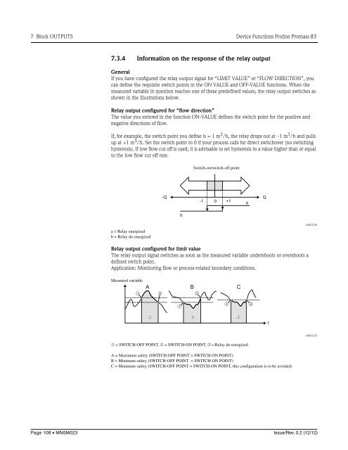
Relay output configured for “flow direction”<br />
The value you entered in the function ON-VALUE defines the switch point for the positive and<br />
negative directions <strong>of</strong> flow.<br />
If, for example, the switch point you define is = 1 m 3 /h, the relay drops out at –1 m 3 /h and pulls<br />
up at +1 m 3 /h. Set the switch point to 0 if your process calls for direct switchover (no switching<br />
hysteresis). If low flow cut <strong>of</strong>f is used, it is advisable to set hysteresis to a value higher than or equal<br />
to the low flow cut <strong>of</strong>f rate.<br />
Switch-on/switch-<strong>of</strong>f point<br />
-Q Q<br />
-1 0 +1<br />
a<br />
b<br />
a = Relay energized<br />
b = Relay de-energized<br />
A0001236<br />
Relay output configured for limit value<br />
The relay output signal switches as soon as the measured variable undershoots or overshoots a<br />
defined switch point.<br />
Application: Monitoring flow or process-related boundary conditions.<br />
Measured variable<br />
m<br />
A B C<br />
n<br />
n<br />
m<br />
m<br />
n<br />
o<br />
o<br />
o<br />
t<br />
A0001235<br />
m = SWITCH-OFF POINT, n = SWITCH-ON POINT, o = Relay de-energized<br />
A = Maximum safety (SWITCH-OFF POINT > SWITCH-ON POINT)<br />
B = Minimum safety (SWITCH-OFF POINT < SWITCH-ON POINT)<br />
C = Minimum safety (SWITCH-OFF POINT = SWITCH-ON POINT, this configuration is to be avoided)<br />
Page 108 • MN0M023<br />
Issue/Rev. 0.2 (12/12)


