NetworX NX-8E Panel Configuration Application Note - Keri Systems
NetworX NX-8E Panel Configuration Application Note - Keri Systems
NetworX NX-8E Panel Configuration Application Note - Keri Systems

You also want an ePaper? Increase the reach of your titles
YUMPU automatically turns print PDFs into web optimized ePapers that Google loves.
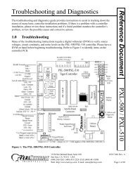
<strong>NetworX</strong> TM <strong>NX</strong>-<strong>8E</strong> Alarm <strong>Panel</strong><br />
The PXL-510 tiger controller can be connected with the <strong>NetworX</strong> 1 <strong>NX</strong>-<strong>8E</strong> Alarm panel to allow arming and disarming<br />
of the alarm system by using the alarm panel keypad, using a wireless Wiegand device, or simply presenting an access<br />
card. This document covers the necessary information for configuring the <strong>NX</strong>-<strong>8E</strong> Alarm panel so that communication<br />
between the alarm panel and the PXL-510 may occur. For instructions on installing the PXL-510 Tiger Controller refer<br />
to the PXL-500/PXL-510 Quick Start Guide (P/N 01918-001). For detailed instructions on installing the <strong>NetworX</strong> <strong>NX</strong>-<br />
<strong>8E</strong> Alarm <strong>Panel</strong> refer to the instructions provided by <strong>NetworX</strong>.<br />
1.0 The <strong>NetworX</strong> <strong>NX</strong>-<strong>8E</strong> Alarm <strong>Panel</strong><br />
In order for communication to take place between the PXL-510 master controller and the <strong>NetworX</strong> <strong>NX</strong>-<strong>8E</strong> Alarm<br />
Control <strong>Panel</strong>, the alarm control panel must be configured to use the <strong>NetworX</strong> <strong>NX</strong>584 protocol. The following steps<br />
will take you through that process. For detailed information concerning the function of the alarm panel, see the <strong>NX</strong>-<strong>8E</strong><br />
Installation Manual.<br />
<strong>Application</strong> <strong>Note</strong><br />
Figure 1: <strong>NetworX</strong> <strong>NX</strong>-<strong>8E</strong> Alarm <strong>Panel</strong><br />
<strong>NetworX</strong> <strong>NX</strong>-<strong>8E</strong><br />
1. <strong>NetworX</strong> is a trademark of GE Interlogix.<br />
1530 Old Oakland Road, Suite 100 01919-001 Rev. 2.0<br />
San Jose, CA 95112 USA<br />
(800) 260-5265 (408) 451-2520 FAX (408) 441-0309<br />
Web: http://www.kerisys.com E-mail: sales@kerisys.com Page 1 of 14
<strong>NetworX</strong> TM <strong>NX</strong>-<strong>8E</strong> Alarm <strong>Panel</strong><br />
<strong>Application</strong> <strong>Note</strong><br />
2.0 Configure the <strong>NX</strong>-<strong>8E</strong> Alarm <strong>Panel</strong><br />
1. When the alarm control panel is first powered up, the LCD shows the following message (see Figure 2).<br />
Figure 2: Alarm <strong>Panel</strong> - System Ready<br />
2. To enter the alarm panel programming mode, select the keys. The alarm panel keypad will beep three<br />
times then prompt for the programming code (see Figure 3).<br />
<strong>NetworX</strong> <strong>NX</strong>-<strong>8E</strong><br />
Figure 3: Alarm <strong>Panel</strong> - Enter Code<br />
3. Enter the programming code for the <strong>NX</strong>-<strong>8E</strong> (the default is set at ) followed by the<br />
key. The alarm panel then prompts for the device address (see Figure 4).<br />
Figure 4: Alarm <strong>Panel</strong> - Enter Device Address<br />
1530 Old Oakland Road, Suite 100 01919-001 Rev. 2.0<br />
San Jose, CA 95112 USA<br />
(800) 260-5265 (408) 451-2520 FAX (408) 441-0309<br />
Web: http://www.kerisys.com E-mail: sales@kerisys.com Page 2 of 14
<strong>NetworX</strong> TM <strong>NX</strong>-<strong>8E</strong> Alarm <strong>Panel</strong><br />
4. Select the key followed by the key. The alarm panel then prompts for the location (see Figure 5). Each<br />
“location” on the alarm panel refers to a different task. Each location may then have a number of segments that<br />
each have their own purpose within the individual location.<br />
Figure 5: Alarm <strong>Panel</strong> - Enter Location<br />
2.1 Serial Port Selector – Location 207<br />
<strong>Application</strong> <strong>Note</strong><br />
1. Enter the location for the Serial Port Selector, which is , followed by the key. Location<br />
207 will appear in the LCD. Select the key to enable the <strong>NetworX</strong> <strong>NX</strong>584 protocol (see Figure 6).<br />
Figure 6: Alarm <strong>Panel</strong> - Location 207<br />
2. Select the key to save the selection. Since Location 207 only has one segment to configure, the LCD returns<br />
to the Alarm <strong>Panel</strong> - Enter Location screen (see Figure 5 on page 3 where the LCD will show the last location<br />
entered in the lower right corner).<br />
<strong>NetworX</strong> <strong>NX</strong>-<strong>8E</strong><br />
1530 Old Oakland Road, Suite 100 01919-001 Rev. 2.0<br />
San Jose, CA 95112 USA<br />
(800) 260-5265 (408) 451-2520 FAX (408) 441-0309<br />
Web: http://www.kerisys.com E-mail: sales@kerisys.com Page 3 of 14
<strong>NetworX</strong> TM <strong>NX</strong>-<strong>8E</strong> Alarm <strong>Panel</strong><br />
<strong>Application</strong> <strong>Note</strong><br />
2.2 Baud Rate Table – Location 208<br />
1. Enter the location for the Baud Rate Table, which is , followed by the key. When the next<br />
location desired is the next sequential location (as it is in this case), selecting the<br />
you to that screen. If you would like to return to the current location, select the<br />
sequential location, select the<br />
key.<br />
key will automatically take<br />
key. To go to the previous<br />
2. After Location 207, enter Location 208 by either entering the location number followed by the key or<br />
selecting the key. Once Location 208 has appeared, select the key for 9600 Baud (the LCD should<br />
look similar to Figure 7).<br />
Figure 7: Alarm <strong>Panel</strong> - Location 208<br />
<strong>NetworX</strong> <strong>NX</strong>-<strong>8E</strong><br />
3. Select the key to save the selection. Since Location 208 only has one segment to configure, the LCD returns<br />
to the Alarm <strong>Panel</strong> - Enter Location screen.<br />
1530 Old Oakland Road, Suite 100 01919-001 Rev. 2.0<br />
San Jose, CA 95112 USA<br />
(800) 260-5265 (408) 451-2520 FAX (408) 441-0309<br />
Web: http://www.kerisys.com E-mail: sales@kerisys.com Page 4 of 14
<strong>NetworX</strong> TM <strong>NX</strong>-<strong>8E</strong> Alarm <strong>Panel</strong><br />
2.3 Programming the <strong>NX</strong>-<strong>8E</strong> Home Automation Protocol – Location 209<br />
1. Enter the location for Programming the <strong>NX</strong>-<strong>8E</strong> Home Automation Protocol, which is , followed<br />
by the key (or following Location #208, select the key). A visible number indicates that particular<br />
option has been turned on. A dash indicates the option is turned OFF. To toggle between OFF and on, select the<br />
corresponding number key on the alarm control keypad. For example, if the number 4 was showing (indicating the<br />
option is on), select the key to turn it OFF. To toggle it back on, select the key again. For this location,<br />
all options must be turned OFF. Once completed, the LCD should look similar to Figure 8).<br />
NOTE: For a more detailed description of the purpose of each numbered option, see the <strong>NX</strong>-<strong>8E</strong> Installation Manual.<br />
<strong>Application</strong> <strong>Note</strong><br />
Figure 8: Alarm <strong>Panel</strong> - Location 209<br />
2. Select the key to save the selection. Since Location 209 only has one segment to configure, the LCD returns<br />
to the Alarm <strong>Panel</strong> - Enter Location screen.<br />
<strong>NetworX</strong> <strong>NX</strong>-<strong>8E</strong><br />
1530 Old Oakland Road, Suite 100 01919-001 Rev. 2.0<br />
San Jose, CA 95112 USA<br />
(800) 260-5265 (408) 451-2520 FAX (408) 441-0309<br />
Web: http://www.kerisys.com E-mail: sales@kerisys.com Page 5 of 14
<strong>NetworX</strong> TM <strong>NX</strong>-<strong>8E</strong> Alarm <strong>Panel</strong><br />
<strong>Application</strong> <strong>Note</strong><br />
2.4 Enabling the <strong>NX</strong>-<strong>8E</strong> Transition-Based Broadcasts – Location 210<br />
1. Enter the location for Enabling the <strong>NX</strong>-<strong>8E</strong> Transition-Based Broadcasts, which is , followed by<br />
the key. This location has two segments that must be configured. For Location 210, Segment 1, all numbered<br />
options must be toggled to the OFF position. Once completed, the LCD will look similar to Figure 9.<br />
Figure 9: Alarm <strong>Panel</strong> - Location 210, Segment 1<br />
2. Select the key to save the selection and move to the next segment. For Location 210, Segment 2, all<br />
numbered options must be toggled to the OFF position. Once completed, the LCD will look similar to Figure 10.<br />
<strong>NetworX</strong> <strong>NX</strong>-<strong>8E</strong><br />
Figure 10: Alarm <strong>Panel</strong> - Location 210, Segment 2<br />
3. Select the key to save the selection and return to the Alarm <strong>Panel</strong> - Enter Location screen.<br />
1530 Old Oakland Road, Suite 100 01919-001 Rev. 2.0<br />
San Jose, CA 95112 USA<br />
(800) 260-5265 (408) 451-2520 FAX (408) 441-0309<br />
Web: http://www.kerisys.com E-mail: sales@kerisys.com Page 6 of 14
<strong>NetworX</strong> TM <strong>NX</strong>-<strong>8E</strong> Alarm <strong>Panel</strong><br />
2.5 Programming the Command/Request Enables – Location 211<br />
4. Enter the location for Programming the Command/Request Enables, which is , followed by the<br />
key. This location has four segments that must be configured. For Location 211, Segment 1, only option<br />
number 8 should be on. Once completed, the LCD will look similar to Figure 11.<br />
Figure 11: Alarm <strong>Panel</strong> - Location 211, Segment 1<br />
<strong>Application</strong> <strong>Note</strong><br />
5. Select the key to save the selection and move to the next segment. For Location 211, Segment 2, only<br />
options numbered 1 and 3 should be on. Once completed, the LCD will look similar to Figure 12.<br />
Figure 12: Alarm <strong>Panel</strong> - Location 211, Segment 2<br />
<strong>NetworX</strong> <strong>NX</strong>-<strong>8E</strong><br />
1530 Old Oakland Road, Suite 100 01919-001 Rev. 2.0<br />
San Jose, CA 95112 USA<br />
(800) 260-5265 (408) 451-2520 FAX (408) 441-0309<br />
Web: http://www.kerisys.com E-mail: sales@kerisys.com Page 7 of 14
<strong>NetworX</strong> TM <strong>NX</strong>-<strong>8E</strong> Alarm <strong>Panel</strong><br />
<strong>Application</strong> <strong>Note</strong><br />
6. Select the key to save the selection and move to the next segment. For Location 211, Segment 3, all<br />
numbered options must be toggled to the OFF position. Once completed, the LCD will look similar to Figure 13.<br />
Figure 13: Alarm <strong>Panel</strong> - Location 211, Segment 3<br />
7. Select the key to save the selection and move to the next segment. For Location 211, Segment 4, only option<br />
number 6 should be on. Once completed, the LCD will look similar to Figure 14.<br />
<strong>NetworX</strong> <strong>NX</strong>-<strong>8E</strong><br />
Figure 14: Alarm <strong>Panel</strong> - Location 211, Segment 4<br />
8. Select the key to save the selection and return to the Alarm <strong>Panel</strong> - Enter Location screen. The alarm panel is<br />
now configured to work in connection with the PXL-510. Select the “Exit” button and the LCD displays the<br />
System Ready message (see Figure 2 on page 2).<br />
1530 Old Oakland Road, Suite 100 01919-001 Rev. 2.0<br />
San Jose, CA 95112 USA<br />
(800) 260-5265 (408) 451-2520 FAX (408) 441-0309<br />
Web: http://www.kerisys.com E-mail: sales@kerisys.com Page 8 of 14
<strong>NetworX</strong> TM <strong>NX</strong>-<strong>8E</strong> Alarm <strong>Panel</strong><br />
3.0 Enable Alarm Control in Doors<br />
Once the <strong>NX</strong>-<strong>8E</strong> is configured to communicate with the PXL-510 controller, the Doors software needs to be enabled for<br />
Alarm Control.<br />
NOTE: Perform an auto configuration on the access control network before trying to enable the Alarm Control feature<br />
in Doors. If no master PXL-510 controller is detected on the network, Alarm Control will not be available for selection.<br />
1. To enable Alarm Control, click on the Setup ⇒ System pull-down menu or click the button on the tool bar.<br />
Click on the System Options tab followed by the<br />
should look similar to Figure 15.<br />
button. The System Options window<br />
<strong>Application</strong> <strong>Note</strong><br />
Figure 15: System Options Tab - Alarm Control OFF<br />
2. The default is for Alarm Control to be turned OFF. Alarm Control can not be enabled if a PXL-510 was not<br />
detected as the master controller on the access control system during the auto configuration. To enable use of the<br />
Alarm Control feature, click in the check box beside the Alarm Control ON field. A check mark appears in the<br />
check box and the following window appears (see Figure 16).<br />
<strong>NetworX</strong> <strong>NX</strong>-<strong>8E</strong><br />
Figure 16: Alarm Control Option Changed Warning - ON<br />
1530 Old Oakland Road, Suite 100 01919-001 Rev. 2.0<br />
San Jose, CA 95112 USA<br />
(800) 260-5265 (408) 451-2520 FAX (408) 441-0309<br />
Web: http://www.kerisys.com E-mail: sales@kerisys.com Page 9 of 14
<strong>NetworX</strong> TM <strong>NX</strong>-<strong>8E</strong> Alarm <strong>Panel</strong><br />
<strong>Application</strong> <strong>Note</strong><br />
3. To enable Alarm Control, click on the button. A “Saved <strong>Configuration</strong>” window flashes on the screen.<br />
4. Now click on the button on the tool bar and update the access control network with the new information.<br />
For details on the update process refer to the Doors Users Guide (P/N 01914-100).<br />
3.1 Disable Alarm Control in Doors<br />
1. To disable Alarm Control, click on the Setup ⇒ System pull-down menu or click the button on the tool bar.<br />
Click on the System Options tab followed by the<br />
should look similar to Figure 17.<br />
button. The System Options window<br />
<strong>NetworX</strong> <strong>NX</strong>-<strong>8E</strong><br />
Figure 17: System Options Tab - Alarm Control ON<br />
2. To disable Alarm Control, click in the Alarm Control ON check box. The check mark that was there disappears and<br />
the following window appears (see Figure 18).<br />
Figure 18: Alarm Control Option Changed Warning - OFF<br />
1530 Old Oakland Road, Suite 100 01919-001 Rev. 2.0<br />
San Jose, CA 95112 USA<br />
(800) 260-5265 (408) 451-2520 FAX (408) 441-0309<br />
Web: http://www.kerisys.com E-mail: sales@kerisys.com Page 10 of 14
<strong>NetworX</strong> TM <strong>NX</strong>-<strong>8E</strong> Alarm <strong>Panel</strong><br />
3. Click the button. A “Saved <strong>Configuration</strong>” window flashes on the screen.<br />
4. Now click on the button on the tool bar and update the access control network with the new information.<br />
For details on the update process refer to the Doors Users Guide (P/N 01914-100).<br />
4.0 Configure Reader in Doors<br />
Once the Alarm Control feature has been enabled and the access control network has been updated, two columns<br />
(Alarm Control Reader Type and Allow Access While Alarm System Offline) are added to the Doors tab in the Setup<br />
System window (see Figure 19). These columns allow for specific configuration of the readers associated with the<br />
Alarm Control panel.<br />
4.1 Assign Alarm Control Reader Type<br />
1. To assign an Alarm Control Reader Type, click on the Setup ⇒ System pull-down menu or click the button<br />
on the tool bar. Then click on the Doors tab. The Doors window appears (see Figure 19).<br />
<strong>Application</strong> <strong>Note</strong><br />
Figure 19: Setup System - Doors Tab<br />
2. Scan down the door name and controller/door address columns and locate a door to be assigned an Alarm Control<br />
Reader Type.<br />
3. Click on the drop-down arrow in the cell corresponding to the selected controller/door. The following options<br />
will appear:<br />
• Access Only – This is used when no Alarm Control panel is in use at that particular reader.<br />
• Arm Only – Presentation of a valid card will arm the alarm. A reader in this mode would not control access to a<br />
door nor disarm the alarm.<br />
• Disarm Only – Presentation of a valid card will disarm the alarm. A reader in this mode would not control access<br />
to a door nor arm the alarm.<br />
• Arm/Disarm – Presentation of a valid card will toggle the state of the Alarm <strong>Panel</strong>. If the Alarm <strong>Panel</strong> is armed,<br />
presentation of a valid card will disarm the alarm. If the Alarm <strong>Panel</strong> is disarmed, presentation of a valid card will<br />
arm the alarm. A reader in this mode will not control access to a door.<br />
• Access/Disarm – Presentation of a valid card will disarm the alarm and grant access to the door.<br />
• Access/Arm – Presentation of a valid card will grant access to the door while arming the alarm. This option is not<br />
recommended because it has the potential to cause false alarms. However, it is available as an option for<br />
special applications.<br />
<strong>NetworX</strong> <strong>NX</strong>-<strong>8E</strong><br />
1530 Old Oakland Road, Suite 100 01919-001 Rev. 2.0<br />
San Jose, CA 95112 USA<br />
(800) 260-5265 (408) 451-2520 FAX (408) 441-0309<br />
Web: http://www.kerisys.com E-mail: sales@kerisys.com Page 11 of 14
<strong>NetworX</strong> TM <strong>NX</strong>-<strong>8E</strong> Alarm <strong>Panel</strong><br />
<strong>Application</strong> <strong>Note</strong><br />
4. Click on the option pertaining to the selected controller/door.<br />
5. Repeat steps 2 through 4 for each controller/door. The resulting window should look similar to Figure 20 on page<br />
12.<br />
Figure 20: Setup System - Alarm Control Reader Type Set<br />
4.2 Allow Access While Alarm System Offline<br />
The Allow Access While Alarm System Offline column gives the operator the option to allow access through a<br />
controlled door even when that controller has lost communication with the alarm control panel or, if the controller is a<br />
slave, with the master controller.<br />
1. The default for the Allow Access column is set to .<br />
2. To allow access while the alarm system is not in communication with the access control network, locate the<br />
cell corresponding to the controller/door that is to allow access. Click on the cell to toggle it to<br />
.<br />
3. Once all the controllers/doors have been assigned an Alarm Control Reader Type and the Allow Access columns<br />
<strong>NetworX</strong> <strong>NX</strong>-<strong>8E</strong><br />
have been set, click on the button. If the changes are not saved before clicking any other button or exiting<br />
the System Setup window, the data entered is lost and must be re-entered.<br />
NOTE: In order for a User to have the ability to control any alarm controlled doors, they must be set up to have<br />
access to the specific controller/door. For further instructions on how to give a User access to a specific controller/<br />
door, see the Doors Users Guide - Section 4: Setup Users (P/N 01914-100).<br />
1530 Old Oakland Road, Suite 100 01919-001 Rev. 2.0<br />
San Jose, CA 95112 USA<br />
(800) 260-5265 (408) 451-2520 FAX (408) 441-0309<br />
Web: http://www.kerisys.com E-mail: sales@kerisys.com Page 12 of 14
<strong>NetworX</strong> TM <strong>NX</strong>-<strong>8E</strong> Alarm <strong>Panel</strong><br />
5.0 Alarm Control Message Text Strings<br />
When the Alarm Control feature is enabled in Doors, an additional tab appears in the Setup Monitors window. There are<br />
87 possible alarm control events that can be tracked. Each event is identified by a message text string that is a brief<br />
description of the event generated by the alarm panel when an event occurs. These strings can be edited by the operator<br />
to be more descriptive, making report viewing easier. There is a 40 character maximum for these text strings. For<br />
detailed information on ways to use the message text strings, refer to the Doors Users Guide (P/N 01914-100).<br />
<strong>Application</strong> <strong>Note</strong><br />
Figure 21: Alarm Control Message Text Strings<br />
5.1 Alarm Control Message Text String Definitions<br />
NOTE: 81 of the message text strings are generated by the alarm panel. For further information on these messages and<br />
what events generate them, refer to the <strong>NetworX</strong> documentation.<br />
Alarm System ARM Request<br />
Reported whenever a card is presented to a reader that has been set as an alarm arming reader.<br />
Alarm System DISARM Request<br />
Reported whenever a card is presented to a reader that has been set as an alarm disarming reader.<br />
Alarm System Request Failed<br />
Reported whenever an arm/disarm request has failed.<br />
Master Communication Restored<br />
Reported whenever communication between a master and slave controller is restored following a loss of<br />
communication.<br />
PXL Slave Lost Communication with Master<br />
Reported whenever communication between a master and slave controller is lost.<br />
<strong>NetworX</strong> <strong>NX</strong>-<strong>8E</strong><br />
1530 Old Oakland Road, Suite 100 01919-001 Rev. 2.0<br />
San Jose, CA 95112 USA<br />
(800) 260-5265 (408) 451-2520 FAX (408) 441-0309<br />
Web: http://www.kerisys.com E-mail: sales@kerisys.com Page 13 of 14
<strong>NetworX</strong> TM <strong>NX</strong>-<strong>8E</strong> Alarm <strong>Panel</strong><br />
<strong>Application</strong> <strong>Note</strong><br />
6.0 Reader Responses to Access Control Events<br />
During day-to-day activity, the reader will respond to access control events in a specific manner. Table 1 provides a<br />
summary of the reader's LED and beeper actions during access control events.<br />
Table 1: Reader Responses to Alarm Status<br />
Reader’s LED and Beeper Status Alarm Condition Alarm Condition Description<br />
solid red LED Alarm Status – Armed Alarm <strong>Panel</strong> is Armed<br />
flashing red LED with beeping Alarm Status – Exit<br />
Delay<br />
Alarm <strong>Panel</strong> is Armed and zones are shunted<br />
for a short time to allow exit of the building<br />
solid amber LED<br />
Alarm Status – Ready to<br />
Arm<br />
Alarm <strong>Panel</strong> is disarmed and can be armed<br />
flashing red LED (only on readers<br />
configured for arming)<br />
short red LED pulse with a short beep<br />
Alarm Status –<br />
Disarmed Zone Fault<br />
Access or Alarm<br />
Request Denied<br />
long red LED pulse with a short beep Alarm Request Denied –<br />
Zone Fault<br />
Zone fault detected, not ready to arm<br />
User does not have permission to access door<br />
or affect alarm condition<br />
User has permission to affect alarm condition,<br />
but a zone is in default not allowing the alarm<br />
to be armed<br />
flashing amber LED Alarm System Offline PXL-510 master has lost communication with<br />
alarm panel; or PXL slave has lost<br />
communication with the PXL-510 master<br />
<strong>NetworX</strong> <strong>NX</strong>-<strong>8E</strong><br />
1530 Old Oakland Road, Suite 100 01919-001 Rev. 2.0<br />
San Jose, CA 95112 USA<br />
(800) 260-5265 (408) 451-2520 FAX (408) 441-0309<br />
Web: http://www.kerisys.com E-mail: sales@kerisys.com Page 14 of 14