Hydraulic - MaxFlight Corporation
Hydraulic - MaxFlight Corporation
Hydraulic - MaxFlight Corporation

Create successful ePaper yourself
Turn your PDF publications into a flip-book with our unique Google optimized e-Paper software.
<strong>MaxFlight</strong><br />
VR2002VR2500<br />
Manual
Section I Operations<br />
APPENDIX A: SITE CONFIGURATION REQUIREMENTS Page 5<br />
CHAPTER 1: INTRODUCTION<br />
1 – 1 Introduction to the VR2002/VR2500 Page 76<br />
1 – 2 Overview of the VR2002/VR2500 Page 6<br />
1 – 3 Specific Ride Information Page 6<br />
1 – 4 Ride Restrictions Page 6<br />
1 – 5 Safety Page 7<br />
CHAPTER 2: OPERATION<br />
2 – 1 Overview of Chapter Page 9<br />
2 – 2 System Startup Procedures Page 9<br />
2 – 3 Description of Passenger Restraint System Page 10<br />
2 – 4 Game Selection Page 10<br />
2 – 5 Customer Pockets Page 10<br />
2 – 6 Height and Weight Page 10<br />
2 – 7 Recommended Passenger Loading Procedures Page 10<br />
2 – 8 Game Start Procedures Page 10<br />
2 – 9 Operation Control Icons Page 11<br />
2 – 10 System Shutdown Page 11<br />
2 – 11 Steering Wheel, Gas Pedal and Brake Pedal Page 12<br />
2 – 12 Emergency Stop Procedures Page 12<br />
2 – 13 Power Interruptions and Restart Procedures Page 12<br />
2 – 14 Ride and Facility Evacuation Procedure Page 13<br />
2 – 15 Ride Termination Conditions Page 13<br />
2 – 16 Operational Restrictions Page 13<br />
2 – 17 Daily Inspection Checklist Description Page 14<br />
CHAPTER 3: SUGGESTED POSTINGS<br />
Emergency Procedure Page 16<br />
Patron Notice (Height and Weight Requirements) Page 17<br />
New Emergency Raise Procedures Page 18<br />
Old Emergency Raise Procedures Page 19<br />
Daily Inspection Checklist Page 15<br />
Section II Technical<br />
CHAPTER 1: REQUIRED MAINTENANCE<br />
1-1 Daily Pre-Opening Inspections and Checks Page 22<br />
1-2 Weekly Maintenance Page 23<br />
1-3 Lubrication Page 24
1-4 Tri-Annual Maintenance Page 24<br />
1-5 Annual Maintenance Page 24<br />
1-6 Extended Periods of Non-Use (6 + Months) Page 24<br />
1-7 Harsh Environment Conditions Page 24<br />
CHAPTER 2: OPERATING LIMITATIONS<br />
2-1 Computer Page 24<br />
2-2 Restraint System Page 24<br />
2-3 <strong>Hydraulic</strong>s Page 24<br />
2-4 Frame and Structure Page 25<br />
2-5 Platform Page 25<br />
CHAPTER 3: SYSTEMS BRIEF<br />
3-1 <strong>Hydraulic</strong> System Page 25<br />
3-2 Electrical System Page 26<br />
CHAPTER 4: TROUBLESHOOTING & REPAIR<br />
4-1 Electrical Page 28<br />
4-2 <strong>Hydraulic</strong> Page 28<br />
4-3 Computer Page 29<br />
4-4 Unscheduled Cessation of Operation Page 29<br />
CHAPTER 5: COMPUTER DIAGNOSTIC SCREENS<br />
5-1 Introduction Page 29<br />
5-2 Layout Page 29<br />
5-3 Troubleshooting Page 30<br />
Pictures of Diagnostic Screens Page 30-35<br />
CHAPTER 6: DRAWINGS / SCHEMATICS<br />
6-1 Introduction Page 36<br />
6-2 Non Destructive Testing Page 36<br />
<strong>MaxFlight</strong> Letter for NDT Page 39<br />
Weekly Inspection Checklist Page 40
Section III Installation<br />
CHAPTER 1: SET UP<br />
1-1 Field Torque Procedure (Turn-of-the-Nut) Page 42<br />
1-2 Assembly Instructions Page 42<br />
APPENDIX B:<br />
INSTALLATION & PERFORMANCE TESTING CHECKLIST Page 47<br />
1. Passenger Seating Areas<br />
2. Frame and Base<br />
3. Projection and Audio Equipment<br />
4. <strong>Hydraulic</strong> System<br />
5. Electrical Equipment<br />
6. Operational Tests<br />
7 Safety Systems and Devices<br />
8. Queue and Holding Areas<br />
9. Building Fire Alarm Interface<br />
Section IV Drawings<br />
A. Electrical<br />
B. Mechanical
APPENDIX A – SITE CONFIGURATION REQUIREMENTS<br />
To determine the site configuration, there are several factors that need careful attention.<br />
1 - Available Floor Space<br />
Each unit has a footprint of 12’ 8” (3.9 m) wide by 15’ (4.6 m) deep, including the loading platform.<br />
Depending on the site topography, the actual configuration will vary.<br />
2 - Ceiling Clearances<br />
The ceiling height requirement is 12’ 8” (3.9 m) with a pathway of approximately 4’ (1.2 m) wide at the<br />
top, 2’ (0.61m) either side of center.<br />
3 - Floor Loading Capabilities<br />
Floors must be able to support the weight of the units. To obtain this information, consult an engineer or an<br />
architect.<br />
Approximate Unit Weight – 4800 lbs. (2181.8 kg)<br />
Load Distribution per Square Foot – 25.26 lbs. (11.4 kg)<br />
4 - Aisle Clearance<br />
Consult local building codes. A minimum of 6’ (1.83 m) is recommended, but should not supersede the<br />
local building codes.<br />
5 - Entrances & Exits<br />
Egress routs must be clear and unobstructed. Local building codes will dictate.<br />
6 - Environment<br />
Keep facility operating temperature reasonably stable. Temperatures less than 80 degrees Fahrenheit with<br />
humidity levels less than 60% would keep patrons comfortable and keep equipment functioning well. Also,<br />
for the best visual effect, facility lighting should be kept low.<br />
Warning – If the environment is not stable it will cause damage to the electronic<br />
equipment.<br />
7 - Floor Finishes<br />
A carpeted floor is the preferred floor finish. Tiled floors and bare concrete floors are okay but may require<br />
placing the machine on an anti-slip pad.<br />
8 - Truck Routes<br />
Depending on the size of the purchase, there could be a need to have access to the facility capable of<br />
accommodating large freight trucks, which require maneuvering room.<br />
9 - Docking<br />
Obtain and forward dock heights before shipping arrangements are made so that accommodations can be<br />
made for the ease of unloading.<br />
10 - Freight Elevators<br />
When installing units that are above the ground or dock level of your facility, examination of freight<br />
elevators for capacities, size and operability is necessary. Schedule time and operators for the day of<br />
delivery where applicable.
11 - Electrical Configurations<br />
U.S. CONFIGURATION<br />
Facilities with available three-phase service need:<br />
A. 2 circuit single-phase, 110 volts, 20 amp, 60 Hz<br />
B. 1 circuit three-phase, 208 volts, 30 amp, 60 Hz<br />
EUROPEAN CONFIGURATION<br />
Facility requirements are:<br />
A. 2 circuit single-phase, 220 volts, 10 amp, 50 Hz<br />
B. 1 circuit three-phase, 230 volts, 20 amp, 50 Hz<br />
HONG KONG CONFIGURATION<br />
Facility requirements are:<br />
A. 2 circuit single-phase, 110 volts, 15 amp, 50 Hz<br />
B. 1 circuit three-phase, 230 volts, 20 amp, 50 Hz<br />
12 - Public Barrier System<br />
Barriers may need to be set up to restrict patrons from coming within reach of the machine while in<br />
operation. It is not the responsibility of <strong>MaxFlight</strong> to provide or install the public barrier system.<br />
CHAPTER 1 – INTRODUCTION<br />
1-1 Introduction to the VR2002<br />
Welcome!! And thank you on your purchase of the VR2002 Cyber Roller Coaster. The VR2002 is the<br />
only full motion interactive experience of it’s kind. This is a dual seat roller coaster based on a virtual<br />
reality environment with a full 360 degree, 2 axis motion platform. The experience time and track selection<br />
can be varied according to patron demand while the standard time set is 2 minutes. You can select various<br />
track layouts thus making each ride as unique as possible.<br />
1-2 Overview of the VR2002<br />
The VR2002 is a computer driven simulator that provides a futuristic roller coaster ride. The customers<br />
can select their own unique track layout. This system allows for the feel of an actual roller coaster without<br />
having to leave the comforts of your facility.<br />
1-3 Overview of the Ride Selection System<br />
The customers can select their own unique track layout. This system is in the form of a<br />
kiosk that enables customers to enter their name and choose between a six (6) or nine (9)<br />
track segment ride from a library of available track pieces, from corkscrews, loops, and<br />
rolls, to drops and tunnels. Once track selection is complete, the customers board the two<br />
(2) passenger cockpit equipped with a huge 58” projection screen and a pulse pounding<br />
surround sound system. Once the cockpit is closed and locked, the passengers embark on<br />
a two (2) to three (3) minute roller coaster ride they will never forget.<br />
1-4 Specific Ride Information<br />
This section has been included in your manual to give you specific and detailed information about the<br />
VR2002 Cyber Coaster. This information complies with the ASTM 698-94 standard (American Society for<br />
Testing and Materials) which governs Physical Information to be provided for Amusement Rides and<br />
Devices.<br />
Ride Speed:<br />
Pitch Axis - 90 Degrees per second (15RPM)
Roll Axis - 90 Degrees per second (15 RPM)<br />
Direction of Travel: Pitch – 360 Degrees<br />
Roll – 360 Degrees<br />
Vertical axis (Y-axis)<br />
Maximum passenger capacity by weight per passenger position: 250 lbs.<br />
Maximum passenger capacity by weight per the total device: 500 lbs.<br />
Maximum passenger capacity by number per the total device: 2<br />
Duration of passenger exposure: 6 segment ride – 2 minutes (approx.)<br />
9 segment ride – 3 minutes (approx.)<br />
Passenger weight distribution:<br />
Maximum Unbalance – 100 lbs.<br />
Environmental restrictions:<br />
Humidity less than 60%<br />
Stable Environment – Temperatures less than 80°F,<br />
Recommended passenger restrictions: Minimum Height – 48”<br />
Mechanical power requirements: The hydraulic system operates at approximately<br />
2000 psi. The hydraulic lift circuit operates at approximately 1200 psi.<br />
Static information:<br />
Height:7’ 9” (approx.)<br />
Width: 12’ 8” (approx.)<br />
Length: 15’ (approx.)<br />
Weight: 4800 lbs.<br />
Dynamic information: Height:12’ 8” (approx.)<br />
Width: 12’ 8” (approx.)<br />
Length: 15’ (approx.)<br />
Weight: 5300 lbs. maximum<br />
Fastener schedule: Refer to the <strong>MaxFlight</strong> VR2002 Cyber Coaster Installation Manual<br />
Maximum static load distribution per footing: NS – based on static weight distributed by<br />
(4) 8” x 16” feet and<br />
(2) 4” x 14” feet<br />
INA = Information Not Available N/A = Not Applicable UNK = Unknown NS =<br />
Not Specified<br />
1-5 Ride Restrictions<br />
All patrons riding the VR2002 Cyber Coaster must meet the following requirements:
1-5A Height Requirements<br />
Patrons riding the VR2002 Cyber Coaster must be taller than 48 inches (1.22 m).<br />
1-5B Impairments<br />
We recommend that patrons with the following impairments/conditions do not ride the VR2002 Cyber<br />
Coaster:<br />
♦ Head, neck, heart or back problems<br />
♦ Recent operations<br />
♦ High blood pressure<br />
♦ Motion sickness<br />
♦ Women who are pregnant<br />
♦ Epileptic patrons; due to the special strobe and lighting effects that are<br />
known to trigger seizures<br />
♦ Intoxicated patrons<br />
♦ Claustrophobia<br />
1-6 Safety<br />
Due to the nature of the VR2002 there are several safety precautions that must be observed in order to<br />
ensure the safety of both the patrons and the operators during operation of the experience.<br />
1-6A Ensure that the cockpit has completed movement prior to continuing with any<br />
other procedures.<br />
1-6B Ensure that during any time the hydraulics are enabled that people stay clear of<br />
the simulator to prevent injury due to the movement of the simulator.<br />
1-6C Ensure that the operating personnel do not operate the simulator with any of the<br />
cover plates removed.<br />
1-6D Ensure that only authorized personnel open the power distribution box for any<br />
reason.<br />
1-6E Ensure that patrons pass the height and weight requirements to ride the simulator.<br />
1-6F Queue Line Safety<br />
The queue line must be kept orderly. The patrons must remain behind the established<br />
barriers while waiting their turn to ride. The queue line should also be used to familiarize<br />
patrons with the operation of the Occupant Panic Switch (OPS) Button as well as the<br />
track selections.<br />
1-6G Loading/Unloading Safety<br />
During the loading and unloading of patrons, the operator must ensure that the simulator<br />
has come to a complete stop prior to opening the cockpit. The operator is required to<br />
assist the patrons to negotiate the platform and cockpit.
1-6H During the operation of the simulator, the operator must stay within the proximity<br />
of their assigned units. Operators must watch for such things as equipment failure, abuse<br />
of the simulator and customers who wish to terminate game play.<br />
1-6I During the operation of the ride, the operator(s) should be posted at the podium<br />
where the computer screen, mouse and unit will be in his/her direct line of sight.<br />
CHAPTER 2 – OPERATION<br />
2-1 Description of Motion During Operation<br />
There are three basic axes of motion that the simulator travels on, Pitch, Roll and vertical lift into the game<br />
position.<br />
2-1A The Pitch Axis<br />
The pitch axis will rotate the cockpit in either a clockwise or counterclockwise direction. The maximum<br />
velocity the pitch axis will produce is 90 degrees per second.<br />
2-1B The Roll Axis<br />
The roll axis will rotate the cockpit in either a clockwise or counterclockwise direction.<br />
The maximum velocity the roll axis will produce is 90 degrees per second.<br />
2-1C The Vertical Lift System<br />
The vertical lift system raises and lowers the main assembly into the load and ride positions.<br />
2-2 System Startup Procedures<br />
The procedures listed below must be followed in order to ensure the simulator operates in<br />
a safe condition.<br />
1. Verify that the GREEN power light is on inside the power distribution box.<br />
2. Turn MAIN POWER switch ON (left switch on the power distribution box).<br />
3. Turn on the computer and monitor – allow time for the system to start up.<br />
4. Double click on the VR2002 icon, a control box will appear.<br />
5. Click on CONTROL.<br />
6. Click on START.<br />
7. When program is initialized, turn COCKPIT POWER switch ON.<br />
8. Turn on the projector in the cockpit using the gray remote or by manually pushing the RED button<br />
on the projector.<br />
9. Pull the RED <strong>Hydraulic</strong> E-Stop UP; depress the green start switch.The system will be ready for<br />
operation in ten (10) minutes.<br />
2-3 Height and Weight<br />
‣ Maximum total weight for the ride is 500 lbs. (226.8 kg) with no more than a 100 lb. (45.4 kg)<br />
difference between the passengers.<br />
‣ Minimum height requirement for the ride is 48 in. (1.22 m)<br />
2-4 Game Selection<br />
Patrons should be encouraged to make their game selections while waiting in the queue line.
2-5 Customer Pockets<br />
The attendant should ask each patron if they have any objects in their pockets that could<br />
come out during the ride. If so, remove and place the items in a secure container for the<br />
duration of the ride. Be sure to remind patrons at the end of their ride to retrieve their<br />
possessions.<br />
2-6 Recommended Passenger Loading Procedures<br />
Assist the passenger into the cockpit and tell them to put on the primary restraint, the<br />
seatbelt. Lower the restraint harness until it is snug against the waist and chest. Render<br />
any assistance or instructions required. This is a good time to give the patrons<br />
instructions on how to use the Occupant Panic Switch. After it has been explained, they<br />
should be asked if they understand how to use it. Close the canopy and secure it with the<br />
locking devise.<br />
2-7 Description of Passenger Restraint System<br />
There are two restraint systems employed for passenger comfort and safety, a primary<br />
and a secondary.<br />
2-7A Primary Restraint<br />
The primary restraint system is similar to an Airline safety belt. It simply pulls around<br />
the passenger and plugs into the receptacle. It is then tightened with the pulling of the<br />
strap.<br />
2-7B Secondary Restraint<br />
The secondary restraint system consists of a molded structural steel bar shaped to fit the<br />
passenger. The bars are covered with padding and vinyl covers for passenger comfort.<br />
Once lowered into place, the passengers cannot release themselves, preventing<br />
inadvertent discharge. To operate, have the passenger lower the harness to their comfort,<br />
then check it for security and that it is locked.<br />
2-8 Game Start Procedures<br />
2-8A Raising the Unit<br />
With the <strong>Hydraulic</strong> system powered, click on the raise icon. The unit will come up about<br />
two (2) inches and stop to balance. Upon completion of balancing, the unit will continue<br />
raising up to the upper limit switches. If the unit does not balance within three (3)<br />
minutes, lower the unit and retry.<br />
NOTE: The weight limit is 500 pounds.<br />
2-8B Configuring the Game<br />
There are four standard track options; each one presents a different perspective of the<br />
roller coaster operation. In addition to the standard layout, a kiosk allows the customers<br />
to select the individual track segments they want. The options are as follows: 1)<br />
Customer Track Selection (If KIOSK is used)<br />
2) Nine Segment Standard
3) Six Segment Standard<br />
4) Nine Segment Random<br />
5) Six Segment Random<br />
2-8C Game Start<br />
Click on the START icon. The unit will begin to load the required databases for the<br />
game selected.<br />
2-9 Operation Control Icons<br />
There are three (3) icons that can be used during the game by the operator to suspend or<br />
restart the game.<br />
2-9A Pause Icon<br />
Should there be a need to pause the ride, the pause icon will return the unit to the home<br />
position and the computer images will freeze in place.<br />
2-9B Continue Icon<br />
The ‘continue’ icon will restore full motion to the simulator and allow the passengers to<br />
complete the ride.<br />
2-9C Terminate Icon<br />
This icon will terminate the ride and return the unit to the home position.<br />
2-10 Game Over<br />
When the time runs out, the main screen will display GAME OVER. During this time<br />
the unit will return to “home” position. When the unit has completed its movement phase<br />
the computer screen will return to the CONFIGURE GAME display. It is now safe to<br />
lower the unit. Click on the ‘lower’ icon. After the unit has lowered onto the stairway<br />
and all movement has stopped, discharge the patron.<br />
2-11 System Shutdown<br />
At the end of the operating day, follow these procedures to ensure that the simulator is<br />
safely secured for the day.<br />
1. Lower the passenger restraint harness to the down position.<br />
2. Turn off the projector by either using the gray remote or by pushing the RED<br />
button on the projector.<br />
3. Push the <strong>Hydraulic</strong> E-Stop button down.<br />
4. Click on the VR2002 icon, lower left of Main screen, the Control Box will<br />
appear.<br />
5. Click on CONTROL.<br />
6. Click on STOP.<br />
7. Click on the left corner Start icon.<br />
8. Click on Shutdown.<br />
9. Click on YES.<br />
10.Turn the COCKPIT POWER off after projector cools down.<br />
11.Turm MAIN POWER off, unit is now secured.
2-12 Emergency Stop Procedures<br />
In the event of an emergency follow the procedures described below for the type of emergency.<br />
2-12A Occupant Panic Switch<br />
During the ride the patrons have the ability to initiate a ride abort by depressing the<br />
Occupant Panic Switch (Labeled “Safety Stop” in the cockpit). When this switch is<br />
depressed the ride will return to the “home” position, the video projector will freeze and<br />
the sound will stop. Once the unit is level, lower the unit by clicking the “lower” icon on<br />
the computer screen. When the unit is completely lowered onto the stairway, open the<br />
cockpit door and ask the riders if they would like to continue. If they do not wish to<br />
continue, discharge the passengers following the Passenger Unloading Procedure. If they<br />
wish to continue, close the canopy and secure it with the locking device. Click on the<br />
“raise” icon and once the unit is completely balanced and raised click on the “continue”<br />
icon to complete the ride.<br />
2-12A Emergency Termination Procedures<br />
In the event of an emergency not involving the simulator directly, click on the ‘Terminate Game’ icon on<br />
the screen. Wait for the unit to level, then lower the game as normal. In the event that the unit is not<br />
responding to the commands, use the <strong>Hydraulic</strong> Main Shut-Off Switch and terminate the hydraulic pump.<br />
The unit will then have to be lowered manually as described in section 2-12B. Assist the patron out of the<br />
simulator and direct them to the exit.<br />
2-12B Emergency Stop without Electrical Power<br />
The Red Emergency Stop Button on the podium must be depressed IMMEDIATELY; this will disable the<br />
hydraulic system. Level the unit on both the pitch and roll axis. Using the manual down valve on the side<br />
of the unit, lower the unit to the base. Open the canopy and release the restraint harness using the release<br />
pin and assist the patron from the cockpit.<br />
2-13 Power Interruptions and Restart Procedures<br />
Should the power be interrupted, the following procedures should be followed.<br />
2-13A Facility Emergency Lighting<br />
Facility emergency lighting must be configured to allow attendants and patrons enough lighting to safely<br />
exit the ride.<br />
2-13B Restart Procedure<br />
Even if the power comes back on before all of the units have been lowered, do not turn the <strong>Hydraulic</strong>s back<br />
on, continue to lower the unit(s) to their lowered position. At this time you can follow the normal Start-up<br />
procedures.
2-14 Ride and Facility Evacuation Procedure<br />
Terminate the ride from the PC. Quietly and calmly, have the queue line begin exiting the facility. Lower<br />
the unit(s), open and unbuckle all patrons and assist with the evacuation of the facility. Follow the system<br />
shut down procedure if time permits or at least make sure that all power is turned off to the hydraulics, the<br />
computer and the power distribution box. NOTE: It is most important that the power to the hydraulics is<br />
disabled and can be quickly accomplished.<br />
2-15 Ride Termination Conditions<br />
1. Any abnormal vibration or abrupt motion changes that would not be considered part of the normal<br />
operation.<br />
2. Any undue movement of either the fiberglass, covering panels, A-frames or any hinges or fabricated<br />
metal that would indicate fatigue, fracture or loose bolts.<br />
3. Any hydraulic fluid which would appear to be a leak or an abnormal amount of collection.<br />
4. Any type of electrical problem that would effect continuation of the game and could include electrical<br />
problems within the building that could inadvertently affect the operation of the simulator.<br />
5. Any computer malfunction which would include system lock-up, program termination or any other<br />
condition that would affect game play.<br />
6. Any condition with the hydraulics that is abnormal (i.e. the TV set showing a roll where the simulator<br />
remains stationary).<br />
7. Any loose objects that roll around inside the cockpit as these items would damage the patron as well as<br />
the components inside the cockpit.<br />
8. Any signs that the concrete anchors may be loose by allowing the unit to walk or move.<br />
9. Any signs of smoke or sparks which would indicate the potential for fire.<br />
10. Any condition where the passenger was tampering with the system such as pounding on the fiberglass<br />
or undue pressure on the cockpit.<br />
2-16 Operational Restrictions<br />
There are certain conditions that the machines should not be operated under. These conditions are<br />
described below.<br />
2-16A Intoxication<br />
If a patron is under the influence of any drugs or alcohol they should not be allowed to utilize the<br />
equipment.<br />
2-16B Heart Conditions<br />
Any heart or other similar condition would preclude a passenger from riding the simulator.<br />
2-16C Pregnancy<br />
It is not recommended that women who are pregnant ride the simulator.<br />
2-16D Weight and Height Restrictions<br />
The patrons must be at least 48” (1.22 m) tall and total weight is not to exceed 500 lb. (226.8 kg) with no<br />
more than a 100 lb. (45.36 kg) difference between the passengers.
2-16E Electrical Storms<br />
It is up to the discretion of the owner operator to operate during an electrical storm. However, it is NOT<br />
recommended to rely on the internal facility safe guards to protect the equipment. When in doubt, shut<br />
down the system to ensure safety of not only the passengers but also the safety of the system.<br />
2-17 Daily Inspection Checklist Description<br />
The Daily Checklist is to be completed by the first shift attendant operating the VR2002 as well as the<br />
second shift attendant (if applicable) at the beginning of his/her shift. These sheets must be filled out on a<br />
daily basis. DO NOT check off the items in the checklist unless you have performed the required<br />
inspection. This maintenance is required to maintain optimum performance of the VR2002. The master<br />
copy of this checklist can be found at the end of the Operator’s Manual.<br />
CHAPTER 3 – SUGGESTED POSTINGS<br />
This chapter contains notices that we suggest be placed near the unit to promote the<br />
safety of patrons as well as operators and to ensure proper operation of the ride.
<strong>MaxFlight</strong> <strong>Corporation</strong><br />
750 Airport Road ◦ Lakewood, NJ 08701<br />
Phone: (732) 942-9898 Fax: (732) 942-1114<br />
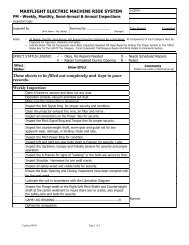
VR2002 Daily Inspection Checklist<br />
Date of Inspection:<br />
AM Inspected By:<br />
PM Inspected By:<br />
* These sheets must be filled out completely and kept in your records.<br />
AM Check PM Check<br />
Make sure the surge suppressor is operating properly (green light)<br />
Inspect projector for proper operation and cleanliness<br />
Make sure that the ductwork is secure and functioning properly<br />
Check to see canopy sensor works properly<br />
_____ ______ Make sure the sound system and speakers are secure and operational<br />
______<br />
Make sure the Occupant Panic Switch is functioning properly<br />
Inspect harnesses for proper operation and condition<br />
Inspect seat belts for proper operation and condition<br />
Make sure safety clips are secured properly<br />
Make sure the screen assembly and padding are secure and in good condition.<br />
Make sure canopy alignment pins are tight<br />
Inspect the Cockpit latch for proper operation and condition<br />
Check platform (stairway) for any movement<br />
Ensure the Emergency <strong>Hydraulic</strong> Shut Off Switch is functioning properly.<br />
Check for any visible hydraulic fluid<br />
Check the <strong>Hydraulic</strong> Filter Delta-P, if extended, replace filter<br />
Make sure the <strong>Hydraulic</strong> Oil Cooling Fan is plugged in<br />
Make sure radiator is clean<br />
Make sure the tail boom stand is in good condition and its proper position.<br />
Make sure the concealment panel on the tail cover is secure<br />
Ensure that the molding on the tail cover is intact and secure<br />
Make sure tail cover bolts are snug<br />
Inspect fiberglass for any visible damage<br />
Make sure all pine tree fasteners are in place and secure<br />
Check for general ride cleanliness<br />
Visually inspect any entrances, exits, stairways, ramps, fencing, guarding and barricades<br />
Ensure the Manual Lowering Lever is functioning properly<br />
NOTE: When inspection is completed, run one full ride cycle to ensure all system components function prop
EMERGENCY PROCEDURE<br />
POSTINGS<br />
Emergency Stop Procedure<br />
The Red Emergency Stop Mushroom Button MUST be<br />
depressed IMMEDIATELY. This will deactivate the<br />
<strong>Hydraulic</strong> System. The unit will need to be leveled manually<br />
on both the Pitch and Roll axes. On the podium side of the<br />
unit, there is a manual let down lever on the inside rear cover<br />
panel. Push the lever down until the unit lowers from the<br />
elevated position. Open the canopy, pull the Quick Release pin<br />
on the topside of the harness system and remove the patrons if<br />
necessary.<br />
Ride and Facility Evacuation Procedure<br />
Terminate Game Play from the host PC. Quietly<br />
and calmly, have the Queue line begin exiting<br />
the facility. Lower the unit, open the canopy,<br />
raise the harness(s) and unbuckle the patron(s),<br />
then assist with the evacuation of the facility.
PATRON NOTICE<br />
Maximum Passengers Per Ride: 2<br />
Maximum Combined Weight: 500 lbs. / 226.8<br />
kg<br />
Minimum Height Per Passenger:<br />
48 in. / 1.22 m<br />
This ride is NOT RECOMMENDED for persons who:<br />
‣ Are under the influence of alcohol or any type of drugs.<br />
‣ Are pregnant.<br />
‣ Suffer from Motion Sickness or Claustrophobia.<br />
‣ Anyone having Heart Conditions, Back or Neck Ailments<br />
or any Serious Disabilities.<br />
‣ Epileptic patrons; due to the special strobe and lighting<br />
effects that are known to trigger seizures<br />
All loose articles such as pens, loose change, etc. that may<br />
come off during flight should be removed.<br />
• Patrons have a responsibility to exercise good judgment<br />
and act in a responsible manner while riding the<br />
VR2002/MT3000.<br />
• Patrons have a responsibility to become familiar with and<br />
obey all oral and written warnings and instructions prior to<br />
and during their use of the VR2002/MT3000.<br />
The <strong>MaxFlight</strong> VR2002/MT3000 is intended for the enjoyment of patrons and the above information is for<br />
your safety and well being.
NEW EMERGENCY RAISE PROCEDURES<br />
FOR<br />
HYDRAULIC MACHINES<br />
This Emergency Procedure to be used anytime if/when the Motion Platform lowers in a<br />
abnormal way, ie: Contacts the stands, floor or is stuck half way between all the way UP<br />
or DWN.<br />
1. Anytime an abnormal action occurs on the motion platform the operator<br />
MUST immediately depress the RED E-Stop on the command console.<br />
2. Verify that the E-Stop is depressed.<br />
3. On the Lower Right corner of the Task Bar, Right Click with the mouse on<br />
the icon that contains a Checkmark in a green circle. This opens a<br />
Properties window.<br />
4. Click on Emergency Raise, another control window will open up showing a<br />
STOP and RAISE icon.<br />
5. Pull out the E-Stop, and press the GREEN start button on the command<br />
console. There should be minimum movement of the platform. Both pitch and<br />
roll valves will be disabled or locked thereby holding the platform where it is.<br />
6. Click on RAISE icon, the unit platform will rise to the top. It will do so until<br />
it contacts the upper limit sensors and stop.<br />
7. When motion platform is all the way UP, DEPRESS E-STOP.<br />
8. Manually level the platform in Pitch and Roll.<br />
9. Lower the platform using the manual lowering procedure. Once Pitch/Roll is<br />
level, depress emergency hydraulic lowering lever slightly downward towards<br />
the floor.<br />
10. Lower all the way. When down on the stands open the cockpit and help<br />
patrons out.<br />
11. Call Maintenance for repair and/or unit testing to certify that this unit is safe<br />
to operate.
<strong>MaxFlight</strong> VR2002/VR2500 Emergency Raising<br />
Procedures<br />
NOTE: ONLY APPLICABLE WHEN THE UNIT IS IN THE NOSE/TAIL DOWN<br />
POSITION WEDGED<br />
BETWEEN THE STAIRWAY OR TAIL BOOM<br />
STAND<br />
This occurs when either the operator or a patron<br />
inadvertently lowers the unit prior to the unit being in<br />
the “HOME POSITION” after or during a ride.<br />
Immediately depress the <strong>Hydraulic</strong> Shut-off Switch<br />
With the mouse, left click the “STOP” icon on the<br />
“Maxflight Operator Panel”<br />
With the mouse, bring up the “Maxflight Control<br />
Screen Panel” by clicking on the VR2002/VR2500 icon<br />
on the lower left side of the screen<br />
Click on “Control” then “Stop”<br />
Click on “Settings”, then Settings on the drop down<br />
menu<br />
Click on the counterweight (upper menu bar) and then<br />
click on the “Disable Off Balance Protection” and apply<br />
now<br />
Click on the Lift (upper menu bar) and then change the<br />
“Platform Lower Sensor” from set to clear, apply now<br />
Click on the upper right side the x in the box, select<br />
“NO” and the control panel will appear<br />
Click on “Control” then “Start”<br />
Ensure the Canopy is closed and locked<br />
Pull-up the <strong>Hydraulic</strong> “E-Stop” switch and depress the<br />
green <strong>Hydraulic</strong> start switch
Activate the “Raise” icon with the mouse, the unit<br />
should start raising in its’ present position<br />
If it does not move, check the “Failsafe Sensor” on the<br />
Counterweight Page(Later versions of Software) or<br />
Encoder Page (Earlier versions) and make sure it is not<br />
disabling the <strong>Hydraulic</strong>s<br />
Once in the raised position, manually level the unit and<br />
lower, open canopy and release the patrons.<br />
Call <strong>MaxFlight</strong> immediately at 1-800-563-1880, ext 300<br />
or for overseas locations: 001-732-942-9898 ext 300.<br />
While awaiting the return call, completely turn the unit<br />
off and re-start the unit in accordance with the<br />
<strong>MaxFlight</strong> operating instructions.
<strong>MaxFlight</strong> VR2002<br />
Technical Manual
CHAPTER 1 – REQUIRED MAINTENANCE<br />
1-1 Daily Pre-Opening Inspections and Checks<br />
Listed below are several, but not all areas and items that need inspection to ensure proper ride operation.<br />
Ensure the operators complete the daily inspections in accordance with the inspection<br />
checklist at the end of the operators’ manual.<br />
1-1A Surge Suppressor<br />
At the beginning of each day, the surge suppression system must be inspected to ensure<br />
proper operation. The system has separate channels, the primary and the secondary. A<br />
green light on the suppressor means that the system is operating correctly. If a red light is<br />
illuminated, the system has been surged once and has only one level of protection left.<br />
This also means that it MUST BE REPLACED soon. Two red lights and an audible<br />
alarm means that there is NO PROTECTION left and the unit must be unplugged until<br />
the surge protector is replaced<br />
.<br />
NOTE: The surge will have come from your facility or your local power supplier.<br />
1-1B Start Switch<br />
This switch activates the <strong>Hydraulic</strong> System.<br />
1-1C <strong>Hydraulic</strong> Shut-Off Button<br />
Verify that the <strong>Hydraulic</strong> Shut-Off Button will disable the hydraulic system. If the shut off button does not<br />
disable the hydraulic system, the ride must be repaired prior to any operation for safety concerns.<br />
1-1D Cockpit Assembly<br />
Verify that the cockpit is clean and secure. Inspect the seats and restraint harnesses for operability. Inspect<br />
the speaker system mountings and wire connections. Inspect the latch systems to insure that they are<br />
working properly.<br />
1-1E Canopy Assembly<br />
Inspect the canopy mounting hinges and verify that the mounting screws are tight. Inspect the screen for<br />
cleanliness and verify that it is secured to the framing. Inspect the projector for mounting stability, bulb<br />
operation and that the lens is clean. Inspect the gas lifting ram sub-assemblies for signs of fatigue and the<br />
mounting systems for tightness.<br />
1-1F Tail Boom Cover<br />
Inspect the Tail Boom Cover for and damage. Verify that the weldment cover plates are in place. Verify<br />
that the securing screws are tight.<br />
1-1G Platform and Tail Boom Support<br />
Ensure that the platform has not moved from its designated position. Make sure that the tail boom support<br />
has also not moved away from its position.<br />
NOTE: If the tail boom support is not supporting the tail boom when the unit is lowered,<br />
the unit will not operate properly.<br />
1-1H Torque Arm Assemblies<br />
Inspect the torque arm retaining bolt for tightness and wire locks. Verify that the retaining rings are<br />
secured to the torque arms.<br />
1-1I <strong>Hydraulic</strong> Sub-Assembly
Turn on the hydraulic pump and allow it to warm up for 10 minutes prior to operation. During this time,<br />
complete a visual inspection of the hydraulic system. Check the fluid level in the sight glass, the level<br />
should be between the two black lines. Verify that the hose connections are tight and that the hoses have<br />
not sustained any damage. Verify that the oil-cooling fan is plugged in.<br />
1-1J Panel Fasteners<br />
Ensure that the plastic fasteners are in place and are securing the panels in place.<br />
1-2 Weekly Maintenance<br />
The following section identifies areas of the equipment that need to be checked on a weekly basis.<br />
1-2A Roll Ring Sub-Assembly<br />
Inspect the condition of the roll ring sub-assembly. Verify that the slip rings are free of contaminates that<br />
would interfere with data transmission. Verify that the hydraulic connections are tight and are not leaking<br />
fluid.<br />
1-2B Pitch Ring Sub-Assembly<br />
Inspect the condition of the pitch ring assembly. Verify that the slip rings are free of contaminates that<br />
would interfere with data transmission. Verify that the hydraulic hoses and electrical cables do not do not<br />
bind up during operation. Verify the cable support system is secured to the A-Frame assembly. Lubricate<br />
the pitch arm bearings with a lithium lubricant.<br />
1-2C Key Way Sub-Assemblies<br />
Inspect the keyways for damage and tightness of the bolts. Lubricate the guides with a lithium lubricant.<br />
1-2D Counterweight Sub-Assembly<br />
Inspect the counterweight system, checking for any condition that would interfere with the proper operation<br />
of the counterweight system. Clean and lubricate the counterweight shaft at this time. Inspect the retaining<br />
bolt safety wires and the bolts for tightness.<br />
1-2E Electrical System Sub-Assemblies<br />
Verify that all of the electrical connections are tight. Verify that each of the limit switches operate<br />
correctly.<br />
1-2F A-Frame Sub-Assembly<br />
Verify that the A-Frame assemblies have not moved and that the bolts have not loosened due to vibration.
1-3 Lubrication (See lubrication diagram – Page 27)<br />
1-3A <strong>Hydraulic</strong> Filter Change<br />
Initial hydraulic filter change must be accomplished at or about 50 hours of operation. Each additional<br />
filter change should be accomplished after each 250 hours of operation. For more information on this<br />
procedure, consult the BERENDSEN <strong>Hydraulic</strong> manual provided with your unit.<br />
1-3B Counterweight Worm Gear<br />
Lubricate the counterweight worm gear with wheel bearing grease once a month to insure proper operation<br />
of the counterweight system.<br />
1-4 Tri-Annual Maintenance<br />
Oil samples must be submitted to Berendsen/Vickers every four months in order to maintain the warranty<br />
of the hydraulic system. Please follow instructions per the Berendsen Manual found in your ‘Product<br />
Information Package’.<br />
1-5 Annual Maintenance<br />
The hydraulic pump motor bearings must be greased once a year.<br />
1-6 Extended Periods of Non-Use (6 Months or more)<br />
If the unit is to be stored or left inoperable for periods in excess of six months be aware of the effects the<br />
environment on the equipment. Such things as temperature, humidity, sunlight, oils, solvents, corrosive<br />
liquids/gases and insects can affect the systems.<br />
NOTE: The hydraulic filter must be changed prior to start-up and each circuit should be inspected.<br />
1-7 Harsh Environment Conditions<br />
If conditions exist in which humidity, dust, corrosive materials or any other type of particles that would<br />
collect onto or corrode exposed materials in a fashion thereof, then the scheduled maintenance will be<br />
required twice as frequent as specified in the current time intervals. A determination of the environment<br />
whether it be inside a humid facility or near an exposed opening that moisture can enter or near a dust or<br />
dirt collecting area should be examined. Keeping the system properly lubricated and cleaned will aid in the<br />
longevity of the system.<br />
CHAPTER 2 – OPERATING LIMITATIONS<br />
2-1 Computer<br />
When starting up the computer system, the operator should observe any error indications or signs that the<br />
computer is not functioning correctly. Provided there are no error messages and the game can be<br />
initialized, the system should be cycled at least once to ensure that the computer is functioning properly.<br />
2-2 Restraint System<br />
By raising and lowering the restraint harness you will be able to establish that they are operating properly.<br />
If any part should fail, the unit should be shut down until the repair is made.<br />
2-3 <strong>Hydraulic</strong>s<br />
The hydraulic E-Stop and Starter Switch will turn the hydraulics on and off, the fan should operate after the<br />
temperature reaches 105º F. By completing one cycle without passengers will verify that the hydraulic<br />
systems are functioning correctly. Pitch and Roll motors should follow the selected motion that appears on<br />
the monitor and careful observation should be taken to ensure the unit returns to the proper home position.<br />
Also, the hydraulic fittings and hoses should be free from fluid and all connections should be dry and clean.
2-4 Frame and Structure<br />
A daily inspection of bolts and welds should be accomplished to ensure that there is no metal fatigue or<br />
loose bolts. Loose bolts should be tightened in accordance with <strong>MaxFlight</strong> specifications, however, if there<br />
is any question as to why there are loose bolts, the unit should be shut down and examined to determine any<br />
causes that are not obvious. It is up to the operator to report these conditions to qualified, on-sight<br />
technical personnel only. If there are any stress cracks or cracks in a solid member, the system should be<br />
shut down and examined immediately.<br />
2-5 Platform<br />
If at any time there is a question with the stability of the platform, passengers should not be allowed to<br />
enter the system until an adequate means of entry into the system is available.<br />
CHAPTER 3 – SYSTEMS BRIEF<br />
3-1 <strong>Hydraulic</strong> System<br />
The hydraulic system provides the force for the motion of the unit during operation. The motion base is a<br />
two-axis system with a lifting ram system for raising the unit to the operating position. Each of the main<br />
axes has a hydraulic motor that drives the unit in pitch or roll. The hydraulic fluid, which is under pressure,<br />
is controlled by a combination of computer commands sent to the hydraulic valves, based on the required<br />
position of the unit as dictated by the game program. The computer program knows the position of the unit<br />
by reading the encoders on the pitch and roll axis. The encoders are attached to the rear shaft of each<br />
motor/gear box. The encoders are an electrical device, powered by the 24-volt circuit, which measure the<br />
position of the units. This is done by sending a light beam through a glass disc that has 2,400 dark and<br />
2,400 light lines on it. Each light or dark line sends a pulse to the computer motion control board that<br />
controls the pulses and determines where in pitch or roll the unit is. Further information of this system will<br />
be in the electrical system.<br />
In the roll axis, all units have a Heco/Ross combination gear box and hydraulic motor,<br />
which allows the cockpit to roll. The hydraulic fluid to operate this motor passes through<br />
the roll valve that is located on the hydraulic power unit on the left-hand side on top of<br />
the manifold, as you face it from the front. After the control signal comes from the<br />
computer through the motion control card it is sent to the <strong>Hydraulic</strong> Control Valve as a (+<br />
or –) 10V signal based on the direction required. The valve begins to open proportionally<br />
based on the size of the signal sent hence the name Proportional Control Valve. The size<br />
and + or – nature of the signal will determine how fast the unit rolls and in what<br />
direction. This is accomplished inside the valve by a shuttle moving back and forth and<br />
opening ports to adjust the flow and direction.<br />
Once the fluid starts to flow from the roll valve, it passes via the hydraulic hose to the<br />
hydraulic pitch swivel. The <strong>Hydraulic</strong> Pitch Swivel is located on the end of the left-hand<br />
pitch shaft and has three hoses connected to it. Two of the hoses are for pressure,<br />
forward and reverse. the first is marked GREEN and is connected between port “D” of<br />
the manifold and P3 of the hydraulic swivel. It then goes via hose through the left-hand<br />
pitch shaft to the roll motor located inside the weldment. The second pressure line,<br />
marked BLUE, follows the same path from Port “C” of the manifold to part of the<br />
hydraulic swivel. The third hose (RED) is not under pressure and is a case drain,<br />
connected between the tank and the roll motor located in the weldment.
The pitch valve is located on the pitch motor torque arm, just below the pitch motor.<br />
There are two hoses that are connected to the small side ported sub-plate under the valve.<br />
One hose marked PURPLE is connected directly between the sub-plate (Port “P”) and the<br />
manifold (Port “A”) located on the swivel side, also marked PURPLE. The other hose is<br />
marked GREY at both ends and is connected between Port “B1” of the manifold on the<br />
swivel side directly to the sub-plate (Port “T”) of the motor side. Also coming from the<br />
sub-plate under the pitch valve there are two hoses that go directly up to the pitch motor.<br />
These hoses are alternately under pressure depending on the direction the motor is<br />
commanded to turn. A third hose which is attached to the top of the motor directly and<br />
marked RED is the case drain that provides lubrication to the motor bearings.<br />
WARNING: If a pressurized line is accidentally connected to this port, the unit will<br />
slowly turn until the seals are blown out and oil would be seen leaking from the<br />
front or back of the motor.<br />
The other end of the case drain is attached to the hydraulic unit at one of the return line connections. The<br />
hydraulic lift circuit is comprised of two lifting rams located under the pitch shaft bearing blocks. These<br />
hoses are connected to the output (front) of the hydraulic flow divider. On the backside of the hydraulic<br />
flow divider is the supply and return line, which comes directly from the manifold (Port “F”). One hose,<br />
which is attached to the back of the hydraulic flow divider, is the supply and return line. The other two<br />
lines are connected to the bottom of the lifting rams. The supply and return hose is connected to the<br />
pressure manifold on which is located the up and down pressure valves. These valves are electrically<br />
connected to coils that enable and disable the valves sending pressure to lift the rams driving the upward<br />
and downward motion of the unit.<br />
NOTE: The lift circuit is fail safe in that it requires hydraulic pressure to function in<br />
either the up or down direction, a small spring loaded ball valve in the let down side of<br />
the circuit requires hydraulic pressure to move it, allowing decent. This ball valve<br />
prevents the unit from descending due to a power failure. The operator should be trained<br />
in the emergency procedure to use the emergency let down valve. This valve bypasses<br />
the normal operational fluid flow to the cylinders and directs fluids directly back to the<br />
tank. The rate at which this occurs depends on how far the valve is moved toward the<br />
open position.<br />
WARNING: The Emergency Let Down Valve should be moved toward the<br />
emergency (UP) position SLOWLY, as the machine will immediately start to<br />
descend at a rate determined by the opening of this valve.<br />
3-2 Electrical System<br />
The Power Distribution Box incorporates the nerve center of the <strong>MaxFlight</strong> simulators by allowing signals<br />
and current to control the unit through its operation. It is a very complex unit that involves the use of 120-<br />
volt alternating current, 24-volt direct current and low voltage signal current used to interface with the<br />
computer. These power sources are housed inside the power distribution box that is situated on the bottom<br />
shelf of the console below the computer. The front of the power distribution box consists of two electrical<br />
switches and a circular view window through which the surge protector can be seen and its normal<br />
operation will be indicated by a green light.<br />
The power distribution box contains fourteen (14) connectors, namely the main power,<br />
auxiliary power, cockpit power, pitch valve, roll valve, counterweight, home sensor,
emergency stop, up/down pressure switch, up/down pressure valve, up sensor, down<br />
sensor, pitch encoder and roll encoder numbered in sequence from one (1) to fourteen<br />
(14) in the above order.<br />
The main power uses a male, three prong locking Hubbell connector while the auxiliary<br />
and cockpit powers use a female, three prong locking connector. The auxiliary provides<br />
power to the computer, hydraulics and cockpit power supply, which in turn provides<br />
power for the restraint actuator motors, projector and audio amplifier.<br />
The pitch valve and roll valve connections activate the hydraulic pump initiating the<br />
specific motions of pitch and roll.<br />
The counterweight is used to balance the cockpit and tail section at their vortex, referred<br />
to as the weldment. The balance is obtained by powering a drive motor, located on top of<br />
the weldment, which moves the counterweight back and forth on a shaft as required to<br />
balance the machine. When the pitch valve no longer senses a load, the unit will rise to<br />
its maximum up position.<br />
The home sensor verifies the raised horizontal position from a signal sent to it by a<br />
pressure switch.<br />
The emergency stop switch, located on the joystick, activates the emergency stop<br />
condition, returning the machine to its original horizontal (Home) position. The machine<br />
can then be lowered to the platform by using the raise/lower switch.<br />
The upper and lower limit switches, which are mounted on the center sections of the A-<br />
Frames directly in line with the bearing blocks, signal the computer when the machine is<br />
in the proper position to begin the game (upper) or load and unload passengers prior to or<br />
at the end of the game sequence (lower).<br />
The power distribution box receives its power from the motor starter box, electrical<br />
swivels and the computer.<br />
The motor starter box is the main fuse box where source power connections are made.<br />
Subsequently, the output lines are timer fused, for short circuit protection and fed into the<br />
hydraulic power unit and power distribution box.<br />
The electrical swivels allow current and data signals to flow into the cockpit and<br />
associated devices via a series of rotating rings with brushes that make contact and allow<br />
roll motion through a range of 360 degrees in either direction.<br />
The hydraulic swivel is connected to the electrical pitch swivel and mounted on the lefthand<br />
side of the pitch shaft with input and output connections. The input connections<br />
consist of cockpit power feed (120VAC), grounding wire, left/right phono jacks,<br />
counterweight motor feed, video feed, emergency stop and a data line to the roll encoder.
These signals are then transferred to the center weldment where the power, phono, video<br />
and emergency stop are transferred to the roll electrical swivel and on to the cockpit.<br />
Thus, the unit can be described, from an electrical perspective, as being controlled from<br />
the computer and the power distribution box. Internal printed circuit boards allow the<br />
power box to communicate with the computer, which is the heart of the unit.<br />
CHAPTER 4 – TROUBLESHOOTING & REPAIR<br />
During the course of operations some problems may develop. This chapter has been designated to assist in<br />
the locating and repair of any problem that affects the operation or safety of your simulator. At all times<br />
basic troubleshooting procedures will be the most effective method to use. When working on the electrical<br />
system always check the proper power is present. When troubleshooting the hydraulic system ensure that<br />
the hydraulic accumulator is charged and on line. This chapter has been broken into the following three<br />
sections: Electrical, <strong>Hydraulic</strong> and Computer.<br />
4-1 Electrical<br />
4-1A Check the power supply whenever any problem arises that affects the operation of<br />
the simulator. If power lines are connected and switches are on, then check that all of the<br />
connectors behind the power distribution box are tight and connected as well as all other<br />
connectors on the machine. Vibration of the machine can cause the connectors to loosen<br />
causing intermittent errors.<br />
4-1B After assembly, a check of the connectors must be made to ensure that all the<br />
wires and connectors are correct.<br />
4-1C If after checking for power and verifying connectors the problem still exists,<br />
please contact your authorized service technician or a service repair manager at<br />
<strong>MaxFlight</strong>.<br />
4-2 <strong>Hydraulic</strong><br />
4-2A The hydraulic system should not require any additional maintenance other than<br />
ensuring that the fluid level remains at the specified level and the filter is changed in<br />
accordance with the Berendsen manual. Should the level of fluid start decreasing, check<br />
each of the connectors for leakage and tighten connections. Only qualified service<br />
technicians should work on the hydraulic system due to danger posed by the system<br />
pressure. Refer to the Berendsen Fluid Power Technician Manual for any problem with<br />
the hydraulic system or related equipment.
4-3 Computer<br />
4-3A Ensure that the computer is turned on and communicating with the kiosk, if<br />
installed. The main problem with the computer system occurs whenever the system is<br />
not shut down properly. This will cause the hard disk to become cluttered with<br />
fragmented information storage locations. A scan disk check should clear these<br />
problems.<br />
4-3B The settings for the simulator should not be attempted by anyone except qualified<br />
<strong>MaxFlight</strong> technicians.<br />
4-4 Unscheduled Cessation of Operation<br />
Should at any time any of these systems either A) have a malfunction or significant adjustment, B) a<br />
mechanical, electrical or operational modification or C) have environmental conditions that affected the<br />
operation of the system it must be documented. After the systems in question are rectified a mandatory test<br />
run of at least one cycle without passengers should be accomplished and documented to ensure the safety of<br />
the system.<br />
CHAPTER 5 – COMPUTER DIAGNOSTIC SCREENS<br />
5-1 Introduction<br />
This section is designed to provide you with the necessary settings pages to troubleshoot<br />
any of our simulators. The setup follows the presentation order of the system manager<br />
program. Only the pages that can be altered are listed in this appendix. It has been noted<br />
at several locations that the local computer experts have changed settings in order to<br />
enhance their riding pleasure only to have unbalanced the system causing failures. The<br />
readings displayed within these pages should represent a guideline for your settings only.<br />
Always refer to your machines particular original setting records to return your system to<br />
an operating condition. Never change a setting without authorization from the<br />
<strong>MaxFlight</strong> Technical Support Division.<br />
5-2 Layout<br />
This section focuses on the settings pages required to trouble shoot the system. If a<br />
<strong>MaxFlight</strong> technician has not trained you, do not change any of the settings. The order of<br />
presentation is as follows:<br />
Address<br />
Power<br />
EDS<br />
Path<br />
IO Drivers<br />
Motor<br />
Amplifier<br />
Lift (1) – <strong>Hydraulic</strong><br />
Lift (2) – Electric<br />
Counterweight<br />
Pitch
Roll<br />
Video<br />
Sound<br />
5-3 Troubleshooting<br />
Most problems are not related to the computer settings, they are usually caused by problems such as loose<br />
connections, broken wires or hydraulic leaks. The settings pages can assist a trained technician in<br />
troubleshooting hardware related problems. The key to isolating a malfunction is to check with the<br />
operators as to the operating condition of the machine over the past few days.<br />
IO Drivers/Counterweight
Lift/Amplifier
Mass/<strong>Hydraulic</strong>s
Pitch/Roll
Sound
CHAPTER 6 – DRAWINGS / SCHEMATICS<br />
6-1 Introduction<br />
This section contains identification drawings, electrical schematics and all pertinent<br />
technical drawings to the VR2002 Cyber Roller Coaster.<br />
Please refer to these drawings during all maintenance.<br />
6-2 NONDESTRUCTIVE TEST<br />
6-2A LIQUID PENETRANT<br />
• Remove all paint a minimum of one inch of the weld area.<br />
• Clean area with solvent and allow to dry.<br />
• Apply penetrant to test area allowing ample time to seep into openings.<br />
• Remove penetrant remaining on surface without removing the penetrent from<br />
openings.<br />
• Apply developer.<br />
• Visually examine the weld for penitrant indications in the developer coating.<br />
• Once again clean the tested area of developer and any traces of penetrant.
After inspection of all welds clean the remaining penetrant and developer for future inspections.
May 9, 2000<br />
To: Whom it May Concern<br />
Subject: <strong>MaxFlight</strong> VR2002 NDT Requirements<br />
The <strong>MaxFlight</strong> VR2002 Cyber Roller Coaster is required a Non-<br />
Destructive-Inspection annually in accordance with the <strong>MaxFlight</strong><br />
VR2002 Manual. The initial inspection is performed in-shop prior to<br />
installation at the site. The next inspection is due one year from date of<br />
installation.<br />
Richard J. Mascolo<br />
Technical Support Manager
<strong>MaxFlight</strong> <strong>Corporation</strong><br />
750 Airport Road ◦ Lakewood, NJ 08701<br />
Phone: (732) 942-9898 Fax: (732) 942-1114<br />
VR2002 Weekly Inspection Checklist<br />
Week Ending: Inspected By (print): ____________<br />
Signature: _____________________________________<br />
* These sheets must be filled out completely, kept in your records and faxed to<br />
<strong>MaxFlight</strong> (Attn: Tech. Support) on a weekly basis.<br />
Inspect the Roll ERC (Electrical Rotary Contact) and pins for proper security and condition<br />
Clean the projector fans and lens (DO NOT USE LIQUID CLEANER)<br />
Inspect all connections on the Power Distribution Box for security<br />
Inspect the Pitch ERC and Torque Arm for proper security and condition<br />
Inspect the counterweight shaft, worm gear and guide rail for any apparent wear,<br />
damage, or binding<br />
Inspect left and right key-way bolts (both A-Frames) for security<br />
Inspect the Up/Down, Canopy and Failsafe Sensors for security and proper operation<br />
Inspect the A-Frames for signs of “walking” if unit is not secured to floor<br />
Inspect Harnesses for any weld cracks<br />
Inspect safety-wired and visible bolts for security<br />
Ensure the Daily AM and PM inspections have been complied with for the past<br />
week(See Operators Manual)<br />
Lubricate the unit in accordance with the Lubrication Diagram(page 27 of Technical<br />
Manual)<br />
Inspect the Flange welds of the Right/Left Pitch Shafts and Counterweight Shaft at<br />
the center weldment to insure there are no cracks, also inspect the safetywire and<br />
bolts for security.<br />
Check the security of both Pitch and Roll Encoders, ensure the set screws are tight.<br />
GAME LOG READING<br />
Normal:<br />
Hours:<br />
Annotate any discrepancies from previous week and corrective actions
<strong>MaxFlight</strong> VR2002<br />
Installation Manual
CHAPTER 1 – SET UP<br />
The first thing to do is to check all of the crates according to the packing slip to ensure<br />
that everything has been delivered. Next, identify each crate as to its contents. The<br />
packing slip is written out by crate or carton to help you find the proper components that<br />
will be needed for set up. It will take two or more people to assemble properly and<br />
safely.<br />
1-1 Field Torque Procedure<br />
<strong>MaxFlight</strong> recommends using the Turn-of-the-Nut procedure for all bolts.<br />
Turn-of-the-nut tightening process encompasses a low initial “threshold” torque to achieve “snug nut”<br />
condition followed by a prescribed amount of nut/bolt turning to develop the required pre-load. Nut/bolt<br />
rotation through a prescribed amount eliminates the influence of all friction variables relative to final<br />
accuracies. A one half turn from snug tight on a bolt having a grip length of less than 8 inches will induce<br />
pre-load equal to or slightly over the bolts’ rated proof load. For bolts greater than 8 inches, two-thirds of a<br />
turn beyond snug tight is recommended.<br />
1-2 Assembly Instructions<br />
1-2A Locate the crates containing the A-Frame assemblies. Uncrate the A-frame (s)<br />
and seek out the center section weldments. Lay out all of the other pieces to ensure<br />
everything is there.<br />
1-2B Locate the ½”-13 x 1” bolts and lock washers, 16 of each for each A-Frame. The<br />
30” C-Channel can be loosely bolted to the bottom of the center weldment and to the feet.<br />
Then loosely bolt the longer C-Channel to the feet and to the top of the center weldment.<br />
See reference drawing number EDA-001.<br />
1-2C Stand the A-Frame up and have someone hold it while a string line is stretched<br />
across the bottom of the A-Frame to ensure that they are assembled in a straight line.<br />
After straightening (if needed), tighten all of the bolts on the A-Frame. Repeat for the<br />
other A-Frame. See reference drawing EDA-002. Check that the floor is level then level<br />
the center welded section.<br />
1-2D Locate the ABS panels for the inside of the A-Frames and their fasteners and<br />
attach to the A-Frames. See reference drawing EDA-003.<br />
1-2E Lay down the A-Frames across from one another with the holes for the lateral<br />
stabilizer brackets to the outside.<br />
1-2F Find the center mainframe assembly with the cockpit, uncrate and roll into<br />
position between the A-Frames.<br />
1-2G Locate the pitch arm assemblies and their bolts. Stand up the A-Frames and have<br />
someone hold them. Pay attention to how the units will be facing to ensure the arms are being<br />
installed on the appropriate side. Bolt the pitch arms to the center weldment of the main<br />
frame. See reference drawing EDA-004/EDA-005.<br />
1-2H Safety wire-tie bolts on the pitch arm.
1-2I Elevate the main frame using the transport/raising dolly. See reference drawing<br />
number EDA-006.<br />
1-2J Locate the hydraulic lifting pistons, the piston brackets, the centering brackets for<br />
the bottom and the appropriate fasteners.<br />
1-2K Insert the piston through the hole at the bottom of the A-Frame center weldment.<br />
Bolt the piston bracket to the A-Frame. Then place the u-bolt around the piston and<br />
through the bracket. Bolt the centering brackets on the base of the piston. Install the<br />
hydraulic extension fitting in the bottom of the lifting ram. Lower the main frame down<br />
on top of the pistons. See reference drawing number EDA-007.<br />
1-2L Stand up the A-Frames and slide them into the pitch shafts. Ensure that the thrust<br />
rings are on the shafts loosely prior to application of the A-Frames. See reference<br />
drawing number EDA-006.<br />
1-2M Locate the <strong>Hydraulic</strong> Swivel and Thrust Ring. Install the thrust ring; insert hoses<br />
and electrical lines into the Pitch Shaft. Feed the hydraulic lines and the electrical<br />
harness into the center weldment. Connections are color coded for ease of installation.<br />
See reference drawing number EDA-008.<br />
1-2N Locate and install Pitch Motor with the Torque Arm and Locking Ring. See<br />
reference drawing number EDA-109.<br />
1-2O Make the hydraulic and electrical connections inside and on top of the center<br />
weldment. All connections are color coordinated.<br />
1-2P Locate the encoders, their brackets and their fasteners. Insert the encoder into the<br />
back of each motor, the Pitch and Roll Motor. Be very careful with the encoder, there is<br />
a glass plate inside which can shatter. Be sure to leave at least 1/16” clearance between<br />
the motor shaft and the encoder. Tighten the setscrew in the side of the motor shaft onto<br />
the encoder shaft. Position the bracket over one of the threaded holes in the back of the<br />
motor. Line up the slot in the bracket with the stud on the encoder and tighten bracket<br />
bolt. See reference drawing number EDA-109.<br />
1-2Q At this time the unit(s) can be initially squared up. This will need to be redone<br />
upon completion of assembly. See reference drawing number EDA-010.<br />
SQUARING THE UNIT<br />
Locate the keyways, inside of the weldment on the A-Frames. Using the laser level, from<br />
the top and center of the right keyway, shoot a beam across to the left A-Frame keyway.<br />
The beam should be centered on the left keyway. This will ensure the unit is square.<br />
1-2R Locate the lateral stabilization frames, bolt into place and lower leveling bolt. See<br />
reference drawing number EDA-111.<br />
1-2S The unit can now be mounted to the floor. This is done to prevent the unit from<br />
moving.
NOTE: The A-Frames will be anchored to the floor using (4) ½” x 5-1/2” Grade 5 Wedge<br />
Anchors each,<br />
one (1) in each A-Frame assembly foot.<br />
1-2T At this time have someone go to the front of the cockpit and hold down on the<br />
footrest to counterbalance the unit. Retrieve the tail boom cover and slide over the tail<br />
section allowing the half-moon cut outs in the cover to slide over the pitch arms. Secure<br />
the tail cover from underneath with the knobs. Move the stand under the tail between<br />
knobs and allow tail to rest on the stand. See reference drawing number EDA-112.<br />
NOTE: The tail boom stand will be anchored to the floor with (4) 3/8” x 2-1/4” Grade 5 Wedge<br />
Anchors.<br />
1-2U Locate the ABS concealment panel that sits on top of the main frame cross block<br />
and install. See reference drawing EDA-013.<br />
1-2V The fiberglass cockpit cover can be installed next. With two people carrying the<br />
cockpit, have a third person guide the cockpit and secure the frame to the brackets.<br />
Ensure that the cockpit seats all the way to the back. Connect the Occupant Panic<br />
Switch. See reference drawing number EDA-114.<br />
1-2W Locate the lower rear enclosure panels and fasteners, plug the fans into the power<br />
strip. Now hold the panel up into place ensuring all cabling is secure and away from<br />
fans. Fasten panel into place. See reference drawing number EDA-115.<br />
1-2X Locate the upper rear enclosure panels and fasteners. Fasten panel into place.<br />
See reference drawing number EDA-116.<br />
1-2Y Locate the loading platform and uncrate. Unscrew the support ribs from packing<br />
position and screw ribs into place where marked. Locate the dowel pins, insert into the<br />
holes on the two lower levels and assemble the tiers. Slide into place under the cockpit.<br />
See reference drawing number EDA-117.<br />
NOTE: The steps will be anchored to the floor with (4) 3/8” x 2-1/4” Grade 5<br />
Wedge Anchors, one (1) in<br />
each corner.<br />
1-2Z Locate the hydraulic pump, uncrate and fill with clean, filtered hydraulic fluid.<br />
Fill to the TOP of the sight glass. DO NOT OVERFILL.
NOTE: The fluid should reach approximately ¼” from the top of the sight glass.<br />
1-2aa Roll the pump into place with radiator fins on the outside next to the louvers on<br />
the cabinetry. Save all hose, line and port plugs for future use. See reference drawing<br />
number EDA-118.<br />
1-2bb Locate the hydraulic lines and lay out for identification. Refer to the hydraulic<br />
hose schematic for location and placement. All hoses are color-coded. Make all<br />
remaining connections.<br />
1-2cc Locate the wire harnesses and lay out for identification. Run the long harness<br />
from the electrical cabinet around the back of the machine to the encoder and the valve<br />
coil. Wire tie lines together.<br />
1-2dd Uncrate the cabinetry and begin assembling the sides of the A-Frame covers by<br />
loosely bolting them to the A-Frames. Then slide the top section into place and fasten<br />
with screws (both sides). After the tops are fastened, the sides can be tightened onto the<br />
A-Frame. See reference drawing number EDA-119.<br />
1-2ee Make electrical connection. See reference drawing number EDA-119.<br />
1-2ff Locate the computer stand and uncrate. Fasten the stand to the cover on the<br />
hydraulic/electrical swivel side in front. Feed the electrical lines into the stand and fasten<br />
to cabinet. See reference drawing number EDA-120.<br />
1-2gg Make the hydraulic swivel connections and the valve coil connections on the back<br />
of the electrical cabinet in the podium. They are all color-coded.
1-2hh Locate the ground station computer and uncrate. Place the computer cabinet<br />
inside computer stand on the shelf. Plug into the power strip.<br />
1-2ii Uncrate the monitor and keyboard and place on top of the computer stand. Locate<br />
the cabling and connect the monitor and keyboard to the computer cabinet. Feed cabling<br />
through the hole provided in the top of stand.<br />
1-2jj Make the other connections to the computer coming from the electrical cabinet.<br />
1-2kk Locate the projector and uncrate. Install the projector on the projector mount.<br />
Make the cable connections. Clean lens if necessary.<br />
1-2ll Trapped air will cause a squealing noise; therefore, the system must be purged of<br />
the trapped air in the lines. Purge air from the lift circuit by venting the system into a<br />
container until the fluid is free of bubbles. This should not exceed 45 seconds.<br />
NOTE: Allow the oil to heat up for approximately 10 minutes prior to testing the pressure<br />
of the hydraulic fluid.<br />
System Operating Pressure: The hydraulic system operates at approximately<br />
2000 PSI.<br />
PSI.<br />
<strong>Hydraulic</strong> Lift Circuit: The hydraulic lift circuit operates at approximately 1200<br />
1-2mm Install face panels on the ends of the cabinetry. See reference drawing<br />
number EDA-121.<br />
1-2nn Place the chase way, over the hoses and cabling, that are between the A-Frames<br />
at the back .
APPENDIX B<br />
INSTALLATION AND PERFORMANCE TESTING CHECKLIST<br />
1. PASSENGER SEATING AREAS<br />
<br />
<br />
<br />
<br />
<br />
<br />
<br />
<br />
<br />
<br />
<br />
Check the condition of the cockpit unit for fiberglass body damage or deterioration.<br />
Visually inspect the cockpit unit for loose or missing fasteners.<br />
Visually inspect the seat unit for damage, deterioration and security.<br />
Visually inspect for sharp or protruding objects in the passenger areas.<br />
Check the condition of the floor surface and mats.<br />
Inspect the lap belts (primary restraint) and related operating mechanisms for proper<br />
function, damage and the security of mounting fasteners.<br />
Inspect the overhead restraints (secondary restraint) for proper function and<br />
condition.<br />
Inspect the steps and thresholds for damage or tripping hazards.<br />
Check the cockpit door hinges and gas spring cylinders for condition and proper<br />
operation.<br />
Inspect the seat for loose or missing fasteners and appropriate safety wire.<br />
Inspect the cockpit frame for cracks or deformation.<br />
2. Frame and Base<br />
<br />
<br />
<br />
<br />
<br />
<br />
<br />
<br />
Visually inspect all structural members on the tail boom, A-Frame and the cockpit<br />
attachment point for bent/deformed brackets, cracks or damage in the frame members<br />
or weldments.<br />
Check the frame fasteners for appropriate grade, retaining wire and proper<br />
installation.<br />
Check the counterweight and rail for condition and security.<br />
Check for loose or missing fasteners on the A-Frame and structure.<br />
Visually inspect the anchor points and verify that the A-Frame has not moved.<br />
Check for abnormal wear or contact between structural components.<br />
Visually inspect pivot points and joints for obvious wear.<br />
Check the frame and base for excessive dust buildup and debris.
Inspect the tail boom shroud for security.<br />
Check the pine tree fasteners in the A-Frame panels for security.<br />
Inspect the roll ring system for wear and security.<br />
Inspect the pitch ring and torque arm for security and wear.<br />
3. Projection and Audio Equipment<br />
<br />
<br />
<br />
<br />
<br />
<br />
Visually inspect the projection equipment and speaker mounting fasteners.<br />
Check the fans and ducting for condition and security.<br />
Check the projector for proper operation, cleanliness and security.<br />
Check speakers and audio equipment for security and proper functioning.<br />
Check the projection controls for proper operation.<br />
Check the projection screen for proper mounting, cleanliness and security.<br />
4. <strong>Hydraulic</strong> System<br />
<br />
<br />
<br />
<br />
<br />
<br />
<br />
<br />
<br />
<br />
<br />
<br />
<br />
<br />
<br />
Check for evidence of hydraulic oil leakage.<br />
Check for appropriate reservoir fluid level.<br />
Inspect the <strong>Hydraulic</strong> Power Unit (HPU) for obvious damage and deterioration.<br />
Test the HPU for proper functioning taking note of any abnormal noise, heat,<br />
vibration, or any sign of abnormal condition.<br />
Visually inspect the motor and pump.<br />
Check the security of the hydraulic lines, fittings and connections.<br />
Test the control systems for proper operation.<br />
Inspect the hydraulic hoses for signs of deterioration or chaffing.<br />
Inspect the rotating union for evidence of leakage.<br />
Check the operating temperature of the hydraulic oil during normal operation.<br />
Check the oil cooler for condition and mounting security.<br />
Inspect the HPU safety guards and warning signs.<br />
Inspect the pressure gages and sight glass. The system operates at approximately<br />
2000 PSI and the lift circuit operates at approximately 1200 PSI.<br />
Check the oil filter for proper maintenance. (Replace after first 50 hours and then at<br />
250 hour intervals)<br />
Inspect the lift cylinders for condition and proper operation.
5. Electrical Equipment<br />
<br />
<br />
<br />
<br />
<br />
<br />
<br />
<br />
<br />
<br />
<br />
<br />
<br />
Check the ride related distribution equipment.<br />
Check for proper use of GFCI’s and grounding.<br />
Visually inspect the lighting for proper operation and damage protection.<br />
Visually inspect the condition of the conduit, wiring and connections.<br />
Check for proper condition, operation and labeling of control stations.<br />
Check for accessibility for authorized personnel and guarding against guest access.<br />
Check for proper operation of the control system in the normal operation mode.<br />
Check the monitor and keyboard for normal operation and condition.<br />
Inspect the electrical safety guards and warning signs.<br />
Check the electrical connections on the control box for security.<br />
Verify the proper operation of the limit switches. (2 up, 1 down, 1 canopy and failsafe<br />
1[home positioning sensor] )<br />
Check the condition of the slip rings.<br />
Check the surge suppressor for proper operation (green light).<br />
6. Operational Tests<br />
<br />
<br />
<br />
<br />
<br />
<br />
<br />
<br />
<br />
<br />
Test the emergency stop button at the operator console and the Occupant Panic<br />
Switch inside the cockpit.<br />
Test the operation console controls (CPU menu driven) for proper operation. During<br />
start-up check for any error indications or signs that the computer is not functioning<br />
correctly.<br />
Test the Main and Cockpit switches for proper operation.<br />
Test the operation of the fire alarm interface (alarm should indicate E-stop mode, if<br />
installed).<br />
Test the raise and balance functions.<br />
Test the door interlock switch (Canopy Open Sensor) for proper operation.<br />
Test the house lighting for correct operation.<br />
Test the manual quick release of the harness.<br />
Check the harness release lever for proper operation.<br />
Check the computer diagnostic functions.
7. Safety Systems and Devices<br />
<br />
<br />
<br />
<br />
<br />
<br />
<br />
<br />
<br />
Check for proper operation of the emergency lighting and battery packs.<br />
Check the condition, content and location of all warning and information signs.<br />
Check for classical hazard guarding in the guest areas.<br />
Check the fire extinguishers for condition and location.<br />
Visually check the lap belt for damage and deterioration.<br />
Visually check the shoulder restraint harness for damage and deterioration.<br />
Review the passenger restrictions for compliance to the manufacturer’s<br />
recommendations.<br />
Check the building fire alarm system for activation devices and audible alarms in the<br />
ride area.<br />
Check the evacuation routes for proper clearances and accessibility.<br />
8. Queue and Holding Areas<br />
Visually inspect the queue, walls and fencing for security and damage.<br />
Visually inspect the holding areas and pre-show areas for hazards to guests.<br />
Check for proper queuing techniques.<br />
Check for adequate lighting in the guest traffic areas.<br />
Visually inspect for slip, trip and fall hazards in the queue area.<br />
Check for sharp or protruding objects in or around the queue area.<br />
Check the condition, content and location of all signs.<br />
Check the condition and security of the stairs/platform.<br />
9. Building Fire Alarm Interface (If installed)<br />
The VR2002 is equipped with an Occupants Panic Stop capability, which is used to stop the ride at the<br />
occupants’ request. The circuit is paralleled into the NO contact of the fire alarm system. In case of a fire,<br />
the facility’s fire alarm system will trip, closing the NO contact, thereby initiating the “Panic Stop” circuit.<br />
Upon circuit activation, the system will return to the “Home” position, the video image will freeze and the<br />
sound will stop. If power remains, the platform will be lowered to the platform using the normal operating<br />
procedure. If power fails, the system will be lowered to the platform using the “without power” procedure<br />
as described on Page 4 of the Operators Manual in Paragraph 2-12B. Also, upon lowering the unit to the<br />
platform, the attendant will manually release the hood and manually release the restraint harness by<br />
removing the hold pin and manually raise the harness off of the patron. This procedure requires<br />
approximately 30 seconds.
Section IV Drawings<br />
1. Electrical
2. Mechanical