onCENTER Product Guide - BlueLinx
onCENTER Product Guide - BlueLinx
onCENTER Product Guide - BlueLinx

You also want an ePaper? Increase the reach of your titles
YUMPU automatically turns print PDFs into web optimized ePapers that Google loves.
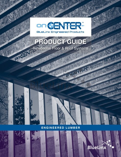
<strong>Product</strong> <strong>Guide</strong> At A Glance<br />
BLI Joists<br />
Introduction………………………………… 4<br />
Design Properties…………………………… 5<br />
Framing System Design Considerations……… 6<br />
Floor Spans………………………………… 7<br />
Bonus Room Floors…………………………… 8<br />
Material Weights……………………………… 9<br />
General Notes for Load Tables………………… 9<br />
Floor Load Table……………………………… 10<br />
Floor Framing System………………………… 12<br />
Illustrated Floor Details……………………… 13<br />
Cantilevers…………………………………… 18<br />
Illustrated Cantilever Details………………… 19<br />
Fire Rated Assemblies……………………… 20<br />
Sound Attentuation Ratings…………………… 20<br />
Holes………………………………………… 21<br />
Roof Spans…………………………………… 22<br />
Roof Load Table ……………………………… 26<br />
Illustrated Roof Details……………………… 28<br />
Roof Slope Factors & Plumb Cut Increases…… 30<br />
Storage and Handling………………………… 30<br />
Safety Precautions…………………………… 30<br />
Bracing Requirements……………………… 31<br />
Installation Notes…………………………… 31<br />
Framing Connectors for BLI Joists…………… 32<br />
<strong>onCENTER</strong> Rim Board………………………… 33<br />
<strong>onCENTER</strong> LVL<br />
Introduction………………………………… 34<br />
LVL Design Properties………………………… 35<br />
Calculating Uniform Loads…………………… 36<br />
Using Load Tables…………………………… 37<br />
2.0E LVL Load Tables………………………… 38<br />
1.9E LVL Load Tables………………………… 44<br />
Bearing Details……………………………… 50<br />
Bearing Length Requirements………………… 51<br />
Multiple-Ply LVL Fastening…………………… 52<br />
USP Structural Connectors for LVL………… 54<br />
Simpson Strong-Tie ® Connectors for LVL……… 55<br />
Holes………………………………………… 56<br />
Storage, Handling & Installation……………… 56<br />
Green Building Certification Eligibility………… 57<br />
Warranty……………………………………… 58<br />
Notes………………………………………… 59<br />
Additional information available online at<br />
www.build<strong>onCENTER</strong>.com<br />
Engineered Lumber Framing Systems<br />
Never be satisifed with anything less than <strong>onCENTER</strong><br />
QUALITY • SERVICE • VALUE<br />
<strong>onCENTER</strong> Delivers QUALITY<br />
• Manufactured in state-of-the-art facilities<br />
• Only the highest quality raw materials used<br />
• Consistent depth<br />
• Produced under controlled conditions that reduce moisture content, resulting in:<br />
<br />
<br />
<br />
more stable products<br />
quieter floor systems<br />
dependability and durability<br />
• Meets strict quality standards per APA-EWS third-party mill inspections<br />
• Backed by a lifetime limited warranty* assuring long-lasting, consistent<br />
performance<br />
<strong>onCENTER</strong> Delivers Superior SERVICE<br />
• Complete framing solutions<br />
• Knowledgeable people behind the products: rely on a field team of experts<br />
available to consult on a project basis from product selection through<br />
installation<br />
• Framing systems backed by a full-service team of engineers and technicians<br />
• <strong>Product</strong> mix tailored to regional market needs<br />
• <strong>BlueLinx</strong> is a leading distributor of building products in North America<br />
2<br />
* Visit www.build<strong>onCENTER</strong>.com or call 877-914-7770 for terms, conditions, and limitations of limited warranty.
<strong>onCENTER</strong> Delivers VALUE<br />
• Our supply chain efficiencies and volume purchasing allow us to<br />
provide quality products cost-effectively<br />
• <strong>onCENTER</strong> Framing Systems can contribute towards green building<br />
certification programs such as LEED ® , Green Globes ® , and the<br />
National Green Building Standard<br />
• FSC ® and SFI ® certified products available<br />
• Cost-effective versus conventional lumber framing by reducing a<br />
project's cycle time with faster installation<br />
<br />
less waste<br />
<br />
long lengths<br />
<br />
lightweight, straight and true products<br />
• Exceed your customer's expectations with strong and quiet floors<br />
that offer the flexibility to open up floor plans for today's lifestyles<br />
<strong>BlueLinx</strong> presents its latest software<br />
offering - DOMA Studio, a powerful, allencompassing<br />
suite of programs to draw and design<br />
in 3D, perform engineering analysis, and optimize<br />
cutting patterns to reduce waste.<br />
3
<strong>onCENTER</strong> BLI Joists<br />
• Lightweight and easy to handle, the I-shaped configuration allows for<br />
longer spans and more load-carrying capacity than dimension lumber<br />
• Manufactured with machine stress rated (MSR) or laminated veneer<br />
lumber (LVL) flanges and an enhanced OSB web<br />
• Low moisture content means greater dimensional stability resulting<br />
in quieter floors and fewer costly callbacks<br />
• Wide flanges provide more support for floor sheathing and more surface<br />
area for nailing, saving time and money<br />
• Available in value lengths up to 48’ (up to 60’ by special order)<br />
4
DESIGN PROPERTIES<br />
2 1 ⁄2"<br />
2 1 ⁄2" 3 1 ⁄2" 3 1 ⁄2" 2 5 ⁄16"<br />
3 1 ⁄2"<br />
9 1 ⁄2", 11 7 ⁄8"<br />
14", 16"<br />
11 7 ⁄8", 14"<br />
16", 18"<br />
11 7 ⁄8", 14"<br />
16", 18"<br />
11 7 ⁄8", 14"<br />
16"<br />
3<br />
⁄8" 3<br />
⁄8" 3<br />
⁄8" 7<br />
⁄16" 3<br />
⁄8"<br />
7<br />
⁄16"<br />
BLI 40 BLI 60 BLI 80 BLI 90 BLI 700 BLI 900<br />
Not all joist series and depths may be available in all locations. Contact <strong>BlueLinx</strong> for local availability.<br />
Design Properties for BLI Joists<br />
Joist<br />
Series<br />
BLI 40<br />
BLI 60<br />
BLI 80<br />
BLI 90<br />
BLI 700<br />
BLI 900<br />
Joist<br />
Depth<br />
EI<br />
(10 6 in 2 -lbs)<br />
Maximum<br />
Moment a,b<br />
(ft-lbs)<br />
Maximum<br />
Shear b<br />
(lbs)<br />
1 3 ⁄4" End<br />
Reaction b,c,d<br />
(lbs)<br />
3 1 ⁄2" Intermediate<br />
Reaction b,c<br />
(lbs)<br />
9 1 ⁄2" 193 2735 1120 1080 2160 2.6<br />
11 7 ⁄8" 330 3545 1420 1200 2500 2.9<br />
14" 482 4270 1710 1200 2500 3.3<br />
16" 657 4950 1970 1200 2500 3.6<br />
11 7 ⁄8" 396 4900 1420 1200 2500 3.2<br />
14" 584 5895 1710 1200 2500 3.4<br />
16" 799 6835 1970 1200 2500 3.7<br />
18" 1046 7895 2250 1250 2500 3.9<br />
11 7 ⁄8" 547 6940 1420 1280 2760 3.7<br />
14" 802 8360 1710 1280 3020 3.9<br />
16" 1092 9690 1970 1280 3100 4.1<br />
18" 1413 11000 2300 1250 3100 4.3<br />
11 7 ⁄8" 601 8515 1420 1280 2760 3.9<br />
14" 877 10255 1710 1280 3020 4.1<br />
16" 1187 11895 1970 1280 3265 4.3<br />
18" 1546 13455 2450 1250 3200 4.5<br />
11 7 ⁄8" 420 6595 1420 1160 2335 2.9<br />
14" 613 7865 1710 1160 2335 3.2<br />
16" 841 9010 1970 1160 2335 3.5<br />
11 7 ⁄8" 661 10255 1925 1400 3355 4.1<br />
14" 965 12235 2125 1400 3355 4.4<br />
16" 1306 14020 2330 1400 3355 4.7<br />
Weight<br />
(plf)<br />
a. No increase permitted for repetitive member use factor.<br />
b. Tabulated values for maximum moment, shear, and reactions are for normal load duration and may be increased for other load durations in accordance<br />
with applicable building codes.<br />
c. Tabulated maximum reactions are without bearing stiffeners. For maximum reactions with bearing stiffeners or with other bearing lengths, visit<br />
www.build<strong>onCENTER</strong>.com.<br />
d. For the maximum end reaction with an end bearing length of 4", use the tabulated maximum shear value. Maximum reactions for end bearing lengths<br />
between 1 3 ⁄4" and 4" may be determined by interpolation. Bearing stiffeners are required for end reactions exceeding 1550 lbs.<br />
4<br />
2<br />
22.5wL 2.308wL<br />
Approximate Deflection (inches) = +<br />
5<br />
EI d×<br />
10<br />
w<br />
L<br />
EI<br />
d<br />
= uniform load (plf)<br />
= span (feet)<br />
= stiffness constant (in 2 -lbs)<br />
= joist depth (inches)<br />
5
FRAMING SYSTEM DESIGN CONSIDERATIONS<br />
<strong>onCENTER</strong> BLI joists provide the floor system designer several<br />
alternatives regarding joist series and depths. Exploring these<br />
options along with the spacing of the joists should enable the<br />
designer to determine the optimal floor with consideration to the<br />
satisfaction of the end-user and the costs associated with the<br />
selection.<br />
The following factors will affect the floor system performance:<br />
• Span<br />
• Spacing<br />
• Depth and series of joist<br />
• Type of subfloor used, and how it is attached<br />
• Elevation of supports<br />
• Presence of gypsum wallboard underneath<br />
• Type of support<br />
• Size of room and contents the floor is supporting<br />
Floor performance may be estimated by the familiar “L/x” fraction,<br />
where "x" is span divided by live load deflection (both in inches).<br />
The traditional building code requirement of L/360 was developed<br />
over a century ago. The wood I-joist industry has found through<br />
experience that I-joist floors should be designed to a more stringent<br />
L/480, which results in a floor that is one-third stiffer than one<br />
designed at the code minimum L/360.<br />
There are other factors that will influence the floor performance.<br />
Gluing the subfloor to the joist framing has been found to<br />
significantly enhance the floor performance. All floor span tables<br />
in this guide reflect this enhancement. A thicker subfloor will<br />
increase composite action with the joists as well as transverse floor<br />
stiffness. X-bridging or BLI blocking panels (refer to detail F21<br />
on page 17) properly installed at the center of the span will also<br />
increase transverse floor stiffness. A gypsum wallboard ceiling<br />
attached directly to the joists will enhance the system performance<br />
by providing damping.<br />
Note that a floor supporting large open areas with minimal furniture,<br />
such as an oversized great room, may be more prone to vibration<br />
than the same floor supporting smaller rooms, since the latter will<br />
have added damping from the partition walls and contents of the<br />
additional rooms.<br />
Quality of workmanship also can contribute to floor performance.<br />
Uneven bearing elevations, while generally not detrimental to the<br />
structural integrity of the building, may result in the perception of a<br />
poor performing floor. A floor with joists supported by beams will<br />
feel less solid than one with joists supported by walls.<br />
With hanger installation, the installer should leave a 1 ⁄16" gap<br />
between the header and joist and firmly seat each joist in the<br />
bottom of the hanger. The gap, firm seating and tight nailing will<br />
help reduce squeaks caused by movement in the hanger.<br />
As part of our commitment to customer service, you may call<br />
<strong>BlueLinx</strong> at 877-914-7770 to discuss your project needs and<br />
determine how the superior performance of <strong>onCENTER</strong> Framing<br />
Systems best fits into your next project.<br />
6
FLOOR SPANS<br />
40 PSF Live Load + 10 PSF Dead Load (L/480)<br />
Joist<br />
Series<br />
BLI 40<br />
BLI 60<br />
BLI 80<br />
BLI 90<br />
BLI 700<br />
BLI 900<br />
Joist<br />
Simple Span<br />
Multiple Span<br />
Depth 12" o.c. 16" o.c. 19.2" o.c. 24" o.c. 12" o.c. 16" o.c. 19.2" o.c. 24" o.c.<br />
9 1 ⁄2" 18'-00" 16'-05" 15'-06" 14'-06" 19'-07" 17'-11" 16'-04" 14'-07"<br />
11 7 ⁄8" 21'-05" 19'-07" 18'-06" 16'-08" 23'-05" 20'-05" 18'-07" 16'-07"<br />
14" 24'-04" 22'-03" 20'-06" 18'-04" 25'-11" 22'-05" 20'-05" 18'-03"<br />
16" 26'-11" 24'-03" 22'-01" 19'-09" 27'-11" 24'-02" 22'-00" 19'-08"<br />
11 7 ⁄8" 22'-07" 20'-08" 19'-06" 18'-02" 24'-08" 22'-06" 21'-02" 19'-07"<br />
14" 25'-09" 23'-06" 22'-02" 20'-08" 28'-00" 25'-07" 24'-01" 19'-09"<br />
16" 28'-06" 26'-00" 24'-07" 22'-10" 31'-01" 28'-04" 24'-09" 19'-09"<br />
18" 31'-03" 28'-06" 26'-11" 24'-10" 34'-01" 29'-09" 24'-09" 19'-09"<br />
11 7 ⁄8" 24'-11" 22'-08" 21'-04" 19'-10" 27'-01" 24'-08" 23'-03" 21'-07"<br />
14" 28'-03" 25'-09" 24'-03" 22'-07" 30'-10" 28'-00" 26'-05" 23'-11"<br />
16" 31'-04" 28'-06" 26'-10" 25'-00" 34'-02" 31'-01" 29'-03" 23'-11"<br />
18" 34'-02" 31'-01" 29'-03" 24'-10" 37'-03" 33'-10" 30'-09" 24'-07"<br />
11 7 ⁄8" 25'-07" 23'-03" 21'-11" 20'-05" 27'-11" 25'-04" 23'-10" 21'-10"<br />
14" 29'-00" 26'-05" 24'-11" 23'-02" 31'-08" 28'-09" 27'-01" 23'-11"<br />
16" 32'-01" 29'-03" 27'-06" 25'-05" 35'-00" 31'-10" 29'-11" 25'-11"<br />
18" 35'-01" 31'-11" 30'-01" 24'-10" 38'-03" 34'-09" 31'-09" 25'-05"<br />
11 7 ⁄8" 23'-00" 21'-00" 19'-10" 18'-06" 25'-01" 22'-10" 21'-07" 18'-06"<br />
14" 26'-01" 23'-10" 22'-06" 20'-11" 28'-05" 25'-11" 23'-02" 18'-06"<br />
16" 29'-00" 26'-05" 24'-11" 23'-01" 31'-07" 27'-10" 23'-02" 18'-06"<br />
11 7 ⁄8" 26'-04" 24'-00" 22'-07" 21'-00" 28'-08" 26'-01" 24'-07" 22'-10"<br />
14" 29'-11" 27'-02" 25'-07" 23'-10" 32'-07" 29'-07" 27'-10" 25'-11"<br />
16" 33'-01" 30'-01" 28'-04" 26'-04" 36'-01" 32'-09" 30'-10" 26'-07"<br />
NOTES:<br />
1. Spans are maximum clear distances between supports, based on uniform loads.<br />
2. Live load deflection is limited to L/480, providing joists that are one-third stiffer than<br />
required by code. Experience has shown that floors designed to the code minimum<br />
live load deflection (L/360) may not meet the occupant's expectations for floor<br />
performance.<br />
3. Spans are based on composite action with glued-nailed APA Rated Sheathing or<br />
Sturd-I-Floor panels of minimum thickness 19 ⁄32" (40/20 or 20 oc) for joist spacing<br />
of 19.2" or less, or 23 ⁄32" (48/24 or 24 oc) for a joist spacing of 24". Apply a ¼"<br />
diameter continuous bead of adhesive (meeting APA AFG-01 or ASTM D 3498) to top<br />
flange of joists. Surfaces must be clean and dry. If adhesive is not used, reduce spans<br />
by 12".<br />
4. Minimum bearing length: 1 3 ⁄4" (end), 3 1 ⁄2" (intermediate).<br />
5. For multiple-span joists, end spans must be at least 40% of adjacent span.<br />
6. Tabulated spans for multiple-span conditions cover a wide range of span<br />
combinations. Neither simple nor multiple spans require bearing stiffeners. Longer<br />
spans may be possible by analyzing a specific span condition and/or by adding<br />
bearing stiffeners. Check using DOMA Sizer software.<br />
7. For loads or deflection criteria other than those shown above, refer to Floor Load Table<br />
on page 10.<br />
7
Bonus ROom Floors<br />
NOTES:<br />
1. LL = live load, TL = total load.<br />
2. In addition to loads shown on the graphic, chart is based on the<br />
following:<br />
- 10 psf floor dead load<br />
- 40 plf kneewall weight<br />
- L/240 total load deflection<br />
- L/480 live load deflection<br />
- Room width centered about garage width<br />
- Floor sheathing glued and nailed along entire length of joist<br />
- Gable roof framing only (no hip framing)<br />
3. For other conditions use DOMA Sizer software or contact<br />
<strong>BlueLinx</strong> at 1-877-914-7770.<br />
DO NOT bevel cut<br />
BLI joist beyond the<br />
inside face of wall.<br />
Bonus Room Joist Selection<br />
Garage<br />
Width<br />
20’<br />
22’<br />
24’<br />
26’<br />
Room<br />
Width<br />
Joist Spacing<br />
12'' o.c. 16'' o.c. 19.2'' o.c. 24'' o.c.<br />
BLI 60 - 11 7 ⁄8" BLI 80 - 11 7 ⁄8" BLI 90 - 11 7 ⁄8"<br />
BLI 40 - 14" BLI 60 - 14" BLI 80 - 14"<br />
BLI 60 - 11 7 ⁄8" BLI 80 - 11 7 ⁄8" BLI 90 - 11 7 ⁄8"<br />
BLI 40 - 14" BLI 60 - 14" BLI 80 - 14"<br />
BLI 60 - 11 7 ⁄8" BLI 80 - 11 7 ⁄8" BLI 90 - 11 7 ⁄8"<br />
BLI 40 - 14" BLI 60 - 14" BLI 60 - 14" 1<br />
BLI 60 - 11 7 ⁄8" BLI 80 - 11 7 ⁄8" BLI 900 - 11 7 ⁄8"<br />
BLI 40 - 14" BLI 60 - 14" BLI 80 - 14"<br />
BLI 80 - 14"<br />
BLI 60 - 11 7 ⁄8" BLI 80 - 11 7 ⁄8" BLI 900 - 11 7 ⁄8"<br />
BLI 40 - 14" BLI 60 - 14" BLI 60 - 14"<br />
BLI 80 - 14" 1<br />
BLI 60 - 11 7 ⁄8" BLI 80 - 11 7 ⁄8" BLI 90 - 11 7 ⁄8"<br />
BLI 40 - 14" BLI 60 - 14" BLI 60 - 14"<br />
BLI 80 - 14" 2<br />
BLI 80 - 11 7 ⁄8" BLI 80 - 14" BLI 90 - 14"<br />
BLI 60 - 14" BLI 60 - 16" BLI 80 - 16"<br />
BLI 80 - 16" 1<br />
BLI 80 - 11 7 ⁄8" BLI 80 - 14" BLI 90 - 14" BLI 900 - 16"<br />
BLI 40 - 14" BLI 60 - 16" BLI 60 - 16" BLI 80 - 16" 3<br />
BLI 80 - 11 7 ⁄8" BLI 80 - 14" BLI 80 - 14" BLI 900 - 16" 1<br />
BLI 40 - 14" BLI 60 - 16" BLI 60 - 16" BLI 80 - 16" 3<br />
BLI 80 - 11 7 ⁄8" BLI 900 - 11 7 ⁄8" BLI 80 - 14" BLI 900 - 14" 2<br />
BLI 40 - 14" BLI 80 - 14" BLI 60 - 16" BLI 80 - 16" 3<br />
BLI 80 - 14" BLI 90 - 14"<br />
BLI 60 - 16" BLI 80 - 16"<br />
BLI 80 - 16" BLI 80 - 18" 3<br />
BLI 900 - 11 7 ⁄8" BLI 90 - 14"<br />
BLI 900 - 16" 2<br />
BLI 80 - 16"<br />
BLI 80 - 14" BLI 80 - 16" BLI 80 - 18" 3<br />
BLI 900 - 11 7 ⁄8" BLI 90 - 14" BLI 80 - 16" BLI 900 - 16" 2<br />
BLI 80 - 14" BLI 80 - 16" BLI 60 - 18" BLI 80 - 18" 3<br />
BLI 900 - 11 7 ⁄8" BLI 80 - 14" BLI 80 - 16" 1 BLI 900 - 16" 3<br />
BLI 60 - 14" BLI 60 - 16" BLI 60 - 18" BLI 80 - 18" 3<br />
8' BLI 40 - 11 7 ⁄8"<br />
10' BLI 40 - 11 7 ⁄8"<br />
12' BLI 40 - 11 7 ⁄8"<br />
10'<br />
12'<br />
14'<br />
10'<br />
12'<br />
14'<br />
16'<br />
12'<br />
14'<br />
16'<br />
18'<br />
1. Minimum bearing length of 2" required.<br />
2. Minimum bearing length of 2 3 ⁄8" required.<br />
3. Bearing stiffeners required.<br />
8
Material Weights<br />
Material<br />
PSF<br />
Ceilings<br />
1<br />
⁄2" gypsum wallboard……………………… 2.0<br />
5<br />
⁄8" gypsum wallboard……………………… 2.5<br />
1" plaster with lath………………………… 8.0<br />
Metal suspension system<br />
w/ acoustical tile…………………………… 1.8<br />
Wood suspension system<br />
w/ acoustical tile…………………………… 2.5<br />
Floors<br />
Carpet and pad…………………………… 2.0<br />
Hardwood (nominal 1")…………………… 4.0<br />
Linoleum or soft tile………………………… 1.5<br />
Ceramic tile ( 3 ⁄8")…………………………… 4.7<br />
Ceramic or quarry tile ( 3 ⁄4")…………………10.0<br />
Marble tile ( 3 ⁄8")…………………………… 5.2<br />
Mortar bed ( 1 ⁄2")…………………………… 6.0<br />
Mortar bed (1")……………………………12.0<br />
GYP-CRETE ® ( 3 ⁄4")………………………… 6.5<br />
Light weight concrete (1 1 ⁄2")…………………12.0<br />
Regular weight concrete (1 1 ⁄2")………………18.0<br />
Framing<br />
12" oc 16" oc 19.2" oc 24" oc<br />
2x4 1.1 0.8 0.7 0.6<br />
2x6 1.7 1.3 1.1 0.9<br />
2x8 2.8 2.1 1.8 1.4<br />
2x10 3.5 2.7 2.2 1.8<br />
2x12 4.3 3.2 2.7 2.2<br />
See page 5 for plf weight of BLI joists.<br />
An additional 1.0 - 2.0 psf is recommended for miscellaneous dead loads.<br />
Material<br />
PSF<br />
Insulation (per 1" thickness)<br />
Extruded polystyrene (XPS)…………………0.16<br />
Fiberglass batts……………………………0.11<br />
Mineral fiber batts (2.5 pcf)…………………0.21<br />
Rigid……………………………………… 1.5<br />
Miscellaneous<br />
4” glass block………………………………18.0<br />
Granite countertop 1 1 ⁄4"……………………18.0<br />
Windows, glass, frame and sash…………… 8.0<br />
Roofing<br />
3-ply ready roofing………………………… 1.0<br />
4-ply felt and gravel……………………… 5.5<br />
5-ply felt and gravel……………………… 6.0<br />
Shingles<br />
Asbestos-cement………………………… 4.0<br />
Asphalt………………………………… 2.5<br />
Clay tile (min.), for mortar add 10 psf………10.0<br />
Concrete tile (MonierLifetile)………… 5.7-10.4<br />
Duration ® ………………………………… 2.3<br />
Duration ® Premium……………………… 2.6<br />
Slate ( 3 ⁄8")……………………………14.0-15.0<br />
Spanish tile………………………………19.0<br />
Wood …………………………………… 3.0<br />
Skylight, metal frame 3 ⁄8" glass……………… 8.0<br />
Material<br />
PSF<br />
Sheathing and Decking<br />
OSB<br />
7<br />
⁄16"……………………………………… 1.4<br />
15<br />
⁄32"…………………………………… 1.5<br />
19<br />
⁄32"…………………………………… 2.0<br />
23<br />
⁄32"…………………………………… 2.4<br />
7<br />
⁄8"……………………………………… 2.9<br />
Plywood<br />
3<br />
⁄8"……………………………………… 1.1<br />
15<br />
⁄32"…………………………………… 1.4<br />
19<br />
⁄32"…………………………………… 1.8<br />
23<br />
⁄32"…………………………………… 2.2<br />
7<br />
⁄8"……………………………………… 2.6<br />
1 1 ⁄8"…………………………………… 3.3<br />
Dimension lumber decking (2" nom.)………… 4.5<br />
18 ga. corrugated metal deck……………… 3.0<br />
20 ga. corrugated metal deck……………… 2.5<br />
Walls - Int. (2x4 wood or NLB steel studs)<br />
1<br />
⁄2" gypsum wallboard (GWB) each side……… 6.0<br />
1<br />
⁄2" GWB one side, plaster one side…………12.0<br />
Plaster both sides…………………………18.0<br />
Walls - Ext. ( 1 ⁄2" GWB, 2x6, 5 1 ⁄2" FG batts)<br />
7<br />
⁄16" OSB, 1 ⁄2" XPS, vinyl siding……………… 8.0<br />
1" XPS, 3 ⁄8" composite siding……………… 8.0<br />
1" XPS, 5 ⁄16" fiber cement siding…………… 9.0<br />
7<br />
⁄16" OSB, 7 ⁄8" stucco on wire mesh…………17.0<br />
7<br />
⁄16" OSB, brick veneer………………………48.0<br />
Note: Wall weights are per square foot of wall<br />
For plf, multiply psf weight by wall height.<br />
GENERal NOTES for LOAD TABLES<br />
1. The uniform load table values on pages 10 and 26 are based on: simple or multiple span<br />
configurations, clear distance between bearing points, and spans of multiple span joists at<br />
least 40% of adjacent spans.<br />
2. Calculated live and total loads must be checked against the tabular values. Live load must<br />
be checked against the Live row and total load against the Total row. Total load will control if<br />
the Live row is blank.<br />
3. The values indicated cover a broad range of applications, none of which require bearing<br />
stiffeners. Greater loads may be possible by analyzing a specific application and/or by<br />
adding stiffeners. Check these and other conditions such as cantilevers and point loads<br />
using DOMA Sizer software.<br />
PSF to PLF Conversion<br />
4. Minimum bearing length: 1 3 ⁄4" (end), 3 1 ⁄2" (intermediate).<br />
5. Local building codes can vary. Prior to installation, confirm that the table deflection criteria<br />
used are accepted in your location.<br />
6. Provide lateral support at all bearing locations and continuous lateral support along the<br />
compression flange of each joist.<br />
7. Table values can be doubled for double joists. Refer to detail F11 for connection information.<br />
8. No additional stiffness from glued and nailed sheathing (composite action) has been<br />
incorporated into tabular values.<br />
Calculating Uniform Loads<br />
Joist Spacing<br />
Load in pounds per square foot (PSF)<br />
Spacing Factor 20 25 30 35 40 45 50 55 60 65 70 75<br />
12" 1.00 20 25 30 35 40 45 50 55 60 65 70 75<br />
16" 1.33 27 33 40 47 53 60 67 73 80 87 93 100<br />
19.2" 1.60 32 40 48 56 64 72 80 88 96 104 112 120<br />
24" 2.00 40 50 60 70 80 90 100 110 120 130 140 150<br />
S1/2<br />
S2/2<br />
S1<br />
S2<br />
Joist Spacing (S1, S2)<br />
⎛S1(ft)<br />
S2(ft) ⎞<br />
⎜ + ⎟ x LL(psf) = LL(plf)<br />
⎝ 2 2 ⎠<br />
⎛S1(ft)<br />
S2(ft) ⎞<br />
⎜ + ⎟ x TL(psf) = TL(plf)<br />
⎝ 2 2 ⎠<br />
Check resulting values against<br />
those in the appropriate uniform<br />
load table.<br />
9
FLOOR LOAD TABLE (PLF)<br />
BLI<br />
100%<br />
Joist<br />
Series<br />
BLI 40<br />
BLI 60<br />
BLI 80<br />
BLI 90<br />
Joist<br />
Depth<br />
9 1 ⁄2"<br />
11 7 ⁄8"<br />
14"<br />
16"<br />
11 7 ⁄8"<br />
14"<br />
16"<br />
18"<br />
11 7 ⁄8"<br />
14"<br />
16"<br />
18"<br />
11 7 ⁄8"<br />
14"<br />
16"<br />
18"<br />
Load Type /<br />
Deflection<br />
Clear Span<br />
6' 7' 8' 9' 10' 11' 12' 13' 14' 15' 16' 17' 18' 19' 20' 21' 22' 23' 24' 25' 26'<br />
L/600 179 136 106 83 67 54 45 37 31 27<br />
Live<br />
L/480 170 132 104 84 68 56 47 39 33<br />
Total L/240 286 244 214 190 171 155 142 125 108 94 83 73 65<br />
L/600 172 137 110 90 75 62 53 45 38 33 29 25 22<br />
Live<br />
L/480 138 113 93 78 66 56 48 41 36 31 28<br />
Total L/240 334 285 249 221 198 180 165 152 140 122 107 95 85 76 69 62 57 52<br />
L/600 128 106 89 75 64 55 48 42 36 32 28 25 22<br />
Live<br />
L/480 112 94 81 69 60 52 46 40 35 31 28<br />
Total L/240 336 287 250 222 199 181 165 153 142 132 124 115 102 92 83 75 69 63 58 53 49<br />
L/600 119 101 86 74 64 56 49 43 38 34 30<br />
Live<br />
L/480 108 93 80 70 61 54 48 43 38<br />
Total L/240 338 288 251 222 200 181 166 153 142 132 124 117 110 104 96 87 80 73 67 62 57<br />
L/600 159 129 106 88 73 62 53 45 39 34 30 26<br />
Live<br />
L/480 132 110 92 78 66 57 49 43 37 33<br />
Total L/240 336 286 250 221 199 181 165 153 142 132 124 116 110 104 95 86 75 66<br />
L/600 126 106 89 76 66 57 50 43 38 34 30 27<br />
Live<br />
L/480 112 96 82 71 62 55 48 42 38 34<br />
Total L/240 339 288 251 223 200 181 166 153 142 132 124 117 110 104 99 94 90 86 80 74 68<br />
L/600 102 88 77 67 59 52 46 41 36<br />
Live<br />
L/480 96 84 74 65 58 51 46<br />
Total L/240 341 290 253 224 201 182 166 153 142 133 124 117 110 104 99 94 90 86 83 79 76<br />
L/600 86 76 67 59 53 47<br />
Live<br />
L/480 84 74 66 59<br />
Total L/240 343 292 254 225 201 182 167 154 143 133 124 117 110 105 99 95 90 86 83 79 76<br />
L/600 168 139 116 97 83 71 61 53 46 40 36<br />
Live<br />
L/480 145 122 104 89 76 66 58 51 45<br />
Total L/240 375 319 278 246 221 201 184 169 157 146 137 129 122 115 109 104 99 90<br />
L/600 138 117 101 87 76 66 58 51 46 41 36<br />
Live<br />
L/480 126 109 95 83 73 64 57 51 45<br />
Total L/240 415 353 307 271 243 220 202 186 172 161 150 141 134 126 120 114 109 104 100 96 92<br />
L/600 116 101 88 78 69 61 55 49<br />
Live<br />
L/480 111 97 86 77 68 61<br />
Total L/240 416 355 309 273 244 221 202 186 173 161 151 142 134 127 120 114 109 104 100 96 92<br />
L/600 112 99 88 78 70 62<br />
Live<br />
L/480 98 87 78<br />
Total L/240 406 349 306 273 246 224 205 190 176 165 154 145 137 130 124 118 112 107 103 99 95<br />
L/600 150 125 105 90 77 66 57 50 44 39<br />
Live<br />
L/480 132 112 96 83 72 63 55 49<br />
Total L/240 377 321 279 247 222 201 184 169 157 147 137 129 122 115 110 104 100 95<br />
L/600 148 127 109 94 82 72 63 56 49 44 39<br />
Live<br />
L/480 118 102 90 79 70 62 55 49<br />
Total L/240 416 354 308 272 244 221 202 186 173 161 151 142 134 127 120 114 109 104 100 96 92<br />
L/600 124 108 95 84 74 66 59 53<br />
Live<br />
L/480 119 105 93 82 74 66<br />
Total L/240 416 358 314 279 252 229 210 194 180 169 158 149 141 133 127 121 115 110 106 101 97<br />
L/600 107 95 84 75 68<br />
Live<br />
L/480 94 85<br />
Total L/240 406 349 306 273 246 224 205 190 176 165 154 145 137 130 124 118 112 108 103 99 95<br />
NOTES:<br />
1. Refer to General Notes on page 9.<br />
2. Live load deflection of L/480 is recommended. For allowable live load at L/360 deflection (minimum code requirement), multiply L/480 values by 1.33. Refer to<br />
page 6 for framing system design considerations.<br />
10
BLI<br />
FLOOR LOAD TABLE (PLF)<br />
100%<br />
Joist<br />
Series<br />
BLI 700<br />
BLI 900<br />
Joist<br />
Depth<br />
11 7 ⁄8"<br />
14"<br />
16"<br />
11 7 ⁄8"<br />
14"<br />
16"<br />
Load Type /<br />
Deflection<br />
Clear Span<br />
6' 7' 8' 9' 10' 11' 12' 13' 14' 15' 16' 17' 18' 19' 20' 21' 22' 23' 24' 25' 26'<br />
L/600 135 111 92 77 65 56 48 41 36 32 28<br />
Live<br />
L/480 116 97 82 70 60 52 45 40 35<br />
Total L/240 314 268 234 207 186 169 155 143 132 123 116 109 103 97 92 88 80 70<br />
L/600 110 93 80 69 60 52 45 40 35 32 28<br />
Live<br />
L/480 100 86 75 65 57 50 44 40 35<br />
Total L/240 317 270 235 208 187 169 155 143 133 124 116 109 103 97 93 88 84 80 77 74 71<br />
L/600 92 80 70 62 54 48 43 38<br />
Live<br />
L/480 77 68 60 54 48<br />
Total L/240 319 272 236 209 188 170 156 143 133 124 116 109 103 98 93 88 84 80 77 74 71<br />
L/600 194 161 135 114 97 83 72 63 55 48 42<br />
Live<br />
L/480 169 143 122 104 90 78 68 60 53<br />
Total L/240 455 391 340 301 270 245 224 206 191 178 167 157 148 140 133 127 121 107<br />
L/600 160 137 118 102 89 78 69 61 54 48 43<br />
Live<br />
L/480 147 128 111 98 86 76 67 60 54<br />
Total L/240 455 391 343 303 272 246 225 207 192 179 168 158 149 141 134 127 121 116 111 107 103<br />
L/600 134 117 103 91 81 72 64 57<br />
Live<br />
L/480 114 101 90 80 72<br />
Total L/240 455 391 343 305 273 247 226 208 193 180 168 158 149 141 134 127 122 116 111 107 103<br />
NOTES:<br />
1. Refer to General Notes on page 9.<br />
2. Live load deflection of L/480 is recommended. For allowable live load at L/360 deflection (minimum code requirement), multiply L/480 values by 1.33. Refer to<br />
page 6 for framing system design considerations.<br />
11
onCenter Floor FRAMING SYSTEM<br />
P2<br />
Dropped ledger<br />
Flush ledger<br />
Masonry hanger<br />
Optional<br />
x-bridging<br />
F15B<br />
F5<br />
F10<br />
F9<br />
F14<br />
F12<br />
F11<br />
C5<br />
F2<br />
Temporary bracing; depicted incomplete.<br />
Refer to BRACING REQUIREMENTS on page<br />
31 for complete bracing information, typ.<br />
F15<br />
F20<br />
F7<br />
Offset bearing walls require<br />
further design evaluation.<br />
F6<br />
C3<br />
C2<br />
F3<br />
12
F1 ATTACHMENT AT END BEARING<br />
BLOCKING PANEL, EXTERIOR<br />
F2<br />
Vertical load transfer = 2000 plf max. (18” – 1700 plf)<br />
One 10d box or sinker nail each side at<br />
bearing, typical for all wood bearings.<br />
1 1 ⁄2" minimum<br />
BLI joist<br />
blocking panel<br />
1 3 ⁄4" minimum bearing length for<br />
all floor and roof details<br />
To minimize splitting of flange and bearing plate,<br />
angle nails and start at least 1 1 ⁄2" from end.<br />
8d nails at 6" o.c. (or 12" o.c. both sides)<br />
Note: For shear transfer, use same nailing<br />
as required for sheathing, but complying<br />
with Installation Note 5, page 31.<br />
F3<br />
BLI RIM JOIST<br />
Vertical load transfer = 2000 plf max. (18” – 1700 plf)<br />
SQUASH BLOCKS & SINGLE RIM<br />
Vertical load transfer = 2000 plf max. along load bearing wall<br />
F4<br />
BLI rim joist<br />
8d nail top and<br />
bottom flange<br />
Toe-nail rim joist<br />
to top flange of<br />
joist with 10d nail.<br />
Minimum 1 3 ⁄4"<br />
joist bearing<br />
Provide backer<br />
for siding<br />
attachment<br />
unless nailable<br />
sheathing is<br />
used.<br />
8d nails at 6" o.c. (or 12" o.c. both sides)<br />
Note: For shear transfer, use same nailing<br />
as required for sheathing, but complying<br />
with Installation Note 5, page 31.<br />
23<br />
⁄32" 48/24 APA Rated<br />
Sheathing where allowed<br />
by local code or use F5<br />
Squash blocks<br />
(2x4 minimum)<br />
1<br />
⁄16"<br />
One 10d box or<br />
sinker nail each<br />
side at bearing<br />
8d nail into top flange<br />
8d nail into bottom<br />
flange or plate<br />
8d nails at 6" o.c.,<br />
toe-nail to plate,<br />
typical.<br />
Note: For shear<br />
transfer, see APA<br />
EWS Y250.<br />
See detail F7 for additional braced wall blocking requirements.<br />
Check local building code for appropriate detail in areas of high lateral load.<br />
F5<br />
<strong>onCENTER</strong> RIM BOARD CLOSURE<br />
Blocking where required by local building<br />
codes for lateral load transfer and/or<br />
optional blocking for diaphragm nailing.<br />
One 2x4 with 1 ⁄8" gap at<br />
top, 8d box nails through<br />
each web into 2x4<br />
Do not butt<br />
ends at joist<br />
location<br />
Weather barrier<br />
<strong>onCENTER</strong><br />
rim board<br />
DECK ATTACHMENT TO RIM BOARD<br />
Exterior Siding<br />
Decking<br />
F6<br />
CAUTION: Insert<br />
lag screw in lead<br />
hole by turning<br />
with a wrench,<br />
not by driving with<br />
a hammer. Avoid<br />
over-torquing<br />
which can<br />
significantly reduce<br />
lateral resistance<br />
of screw.<br />
1<br />
⁄2" sheathing<br />
<strong>onCENTER</strong><br />
rim board<br />
1 1/2"<br />
1 1/2"<br />
3-8d nails<br />
at corners<br />
Check local building code for appropriate detail in<br />
areas of high lateral load.<br />
8d nail top and<br />
bottom flange<br />
8d nails at 6" o.c. toe-nail to plate,<br />
typical. Note: For shear transfer, see<br />
APA EWS Y250.<br />
Rim Board Vertical Load Transfer<br />
1" SE 3300 plf (18" - 2750 plf)<br />
1 1 ⁄8" SE 4400 plf (18" - 3950 plf)<br />
Maintain 2" distance<br />
from center of through<br />
bolt or lag screw to<br />
ledger edges.<br />
Metal flashing (extend 3"<br />
beyond deck joist hanger)<br />
2x PT ledger attached with 1 ⁄2" dia. through bolts with<br />
washers and nuts or 1 ⁄2" lag screws with tip extending<br />
a minimum of 1 ⁄2" beyond rim board (see Installation<br />
Note 11, page 31). Capacity is 350 lbs. (300 lbs. for 1”<br />
SE rim board) per fastener. Bolt/lag screw spacing to<br />
be determined by design vertical and lateral load.<br />
Use high quality caulk to fill holes and seal flashing. 13
F7<br />
BLOCKING PANEL USED FOR BRACING<br />
BEVEL CUT JOIST<br />
F8<br />
Single layer 23 ⁄32" 48/24 APA Rated<br />
Sheathing rim provides 1000 plf vertical<br />
load transfer (two layers = 2000 plf).<br />
Allowed only with joist depths up to<br />
11 7 ⁄8" unless used with 2x4 min. squash<br />
blocks as shown in detail F4. Fasten to<br />
end of joists and plate as indicated for<br />
<strong>onCENTER</strong> rim board in F5.<br />
Do not bevel cut joist beyond<br />
inside face of support.<br />
Note: For shear<br />
transfer, use same<br />
nailing as required<br />
for sheathing, but<br />
complying with<br />
Installation Note 5,<br />
page 31.<br />
Blocking panels installed for<br />
braced wall requirements. Locate<br />
as required by code.<br />
Note: BLI Joist or <strong>onCENTER</strong> rim<br />
board blocking, or x-bridging required<br />
at bearing for lateral support.<br />
Check local building code for appropriate detail in areas of high lateral load.<br />
Check local building code for appropriate detail in areas of high lateral load.<br />
F9<br />
BLOCKING PANEL, INTERIOR<br />
Vertical load transfer = 2000 plf max. (18” – 1700 plf)<br />
SQUASH BLOCKS AT INTERIOR BEARING<br />
Vertical load transfer = 2000 plf max. along load bearing wall<br />
F10<br />
Load bearing wall must stack over blocking and<br />
wall or beam below.*<br />
When joists meet over wall, provide 1 3 ⁄4"<br />
minimum bearing for each joist and install<br />
blocking panel to restrain both joists.<br />
Blocking panels not required when joists<br />
are continuous over wall and no load<br />
bearing wall exists above.<br />
Load bearing wall must stack over blocking<br />
and wall or beam below.*<br />
1<br />
⁄16"<br />
One 10d box or sinker<br />
nail each side at bearing.<br />
8d nail into<br />
top flange<br />
8d nails at 6"o.c. (or 12" o.c. both<br />
sides) or per design professional's<br />
specs., but complying with<br />
Installation Note 5, page 31.<br />
Squash block (2x4 minimum) used<br />
only if load bearing wall exists above.<br />
Bearing wall, <strong>onCENTER</strong> LVL or glulam<br />
beam<br />
8d nail into bottom<br />
flange or plate<br />
* Non-stacking load bearing walls require additional consideration.<br />
* Non-stacking load bearing walls require additional consideration.<br />
Check local building code for appropriate detail in areas of high lateral load.<br />
F11<br />
DOUBLE JOIST CONSTRUCTION WITH FILLER<br />
Note: Filler blocks and fastening between joists can be omitted when double joists are loaded<br />
evenly from above to the tops of both joists, such as when a parallel bearing wall is directly<br />
centered over the double joist.<br />
Filler blocking<br />
14<br />
Joist<br />
Regular Filler Blocking Full-depth Filler Blocking<br />
Series Depth<br />
(Detail F12)<br />
(Details C4, F13, F14 & R7)<br />
BLI 700<br />
11 7 ⁄8"<br />
14"<br />
16"<br />
2x6 + 3 ⁄8" OSB/Plywood<br />
2x8 + 3 ⁄8" OSB/Plywood<br />
2x8 + 3 ⁄8" OSB/Plywood<br />
2x8 + 3 ⁄8" OSB/Plywood<br />
2x10 + 3 ⁄8" OSB/Plywood<br />
2x12 + 3 ⁄8" OSB/Plywood<br />
BLI 40 9 1 ⁄2" 2x6 + 5 ⁄8" OSB/Plywood 2x6 + 5 ⁄8" OSB/Plywood<br />
BLI 40, 60<br />
11 7 ⁄8"<br />
14"<br />
16"<br />
2x6 + 5 ⁄8" OSB/Plywood<br />
2x8 + 5 ⁄8" OSB/Plywood<br />
2x8 + 5 ⁄8" OSB/Plywood<br />
2x8 + 5 ⁄8" OSB/Plywood<br />
2x10 + 5 ⁄8" OSB/Plywood<br />
2x12 + 5 ⁄8" OSB/Plywood<br />
BLI 60 18" 2x8 + 5 ⁄8" OSB/Plywood 2x12 + 5 ⁄8" OSB/Plywood<br />
BLI 80, 90, 900<br />
11 7 ⁄8"<br />
14"<br />
16"<br />
2-2x8<br />
2-2x8<br />
2-2x8<br />
2-2x8<br />
2-2x10<br />
2-2x12<br />
BLI 80, 90 18" 2-2x8 2-2x12<br />
1<br />
⁄8" gap<br />
1. Support back of web during nailing to prevent damage to web-flange connection.<br />
2. Leave 1 ⁄8" gap between top of filler blocking and bottom of top flange.<br />
3. Block solid between joists. For all applications except cantilever reinforcement, filler need<br />
not be one continuous length, but must extend the entire length of span. For double I-joist<br />
cantilever reinforcement C4, filler must be one continuous piece extending the full length of<br />
the reinforcement.<br />
4. Place joists together and nail from each side with 2 rows of 10d common nails (16d common<br />
for BLI 80, BLI 90, and BLI 900) at 12" o.c. Stagger rows on opposite side 6".<br />
12”
F12<br />
FLOOR OPENING, TOP MOUNT HANGERS<br />
Backer Blocks*<br />
Joist Series Material<br />
BLI 700 7<br />
⁄8"<br />
BLI 40, 60 1<br />
⁄2" + 1 ⁄2"<br />
BLI 80, 90, 900 1 1 ⁄2" net<br />
Backer Block (use if hanger load exceeds 250 lbs.)<br />
Before installing backer to double joist, drive an<br />
additional 4-10d common nails through web into filler<br />
where backer will fit. Repeat on back side of double<br />
joist. Install backer tight to top flange. Use 8-10d<br />
common nails (15-10d common nails for BLI 80, 90,<br />
700 and 900 series joists). Stagger nails to avoid<br />
splitting. Clinch nails when possible.<br />
Header can be single or double BLI joist.<br />
Verify capacity to support concentrated<br />
load. Assemble double joist per detail<br />
F11 (regular filler).<br />
Single BLI joist<br />
Backer blocks both sides of web<br />
(per hanger manufacturer).<br />
Joist Depth Block Depth<br />
9 1 ⁄2", 11 7 ⁄8" 5 1 ⁄2"<br />
14" - 18" 7 1 ⁄4"<br />
* Block centered on hanger location.<br />
Minimum length 24”.<br />
A<br />
Hanger from<br />
page 32<br />
B<br />
F13<br />
FLOOR OPENING, FACE MOUNT HANGERS<br />
Backer Blocks*<br />
Joist Series Material<br />
BLI 700 7<br />
⁄8"<br />
BLI 40, 60 1<br />
⁄2" + 1 ⁄2"<br />
BLI 80, 90, 900 1 1 ⁄2" net<br />
Joist Depth Block Depth<br />
9 1 ⁄2" 6 1 ⁄4"<br />
11 7 ⁄8" 8 5 ⁄8"<br />
14" 10 3 ⁄4"<br />
16" 12 3 ⁄4"<br />
18" 14 3 ⁄4"<br />
* Block centered on hanger location.<br />
Minimum length 24”.<br />
Header can be single or double BLI joist.<br />
Verify capacity to support concentrated<br />
load. Assemble double joist per detail<br />
F11 (full-depth filler).<br />
Backer Block<br />
Before installing backer to double joist, drive an<br />
additional 7-10d common nails (4-10d common<br />
nails for BLI 80, 90, 700 and 900 series joists)<br />
through web into filler where backer will fit. Repeat<br />
on back side of double joist. Install backer tight<br />
to top flange. Use 18-10d common nails. Stagger<br />
nails to avoid splitting. Clinch nails when<br />
possible.<br />
A<br />
Unless hanger sides laterally<br />
restrain top flange, bearing<br />
stiffeners are required at<br />
hangers (see detail F18).<br />
Hanger from<br />
page 32<br />
Single BLI joist<br />
Backer blocks both sides<br />
of web<br />
B<br />
F14<br />
STAIR STRINGER TO JOIST CONNECTION<br />
Double BLI joist shown as header.<br />
<strong>onCENTER</strong> LVL may also be used.<br />
Verify header capacity to support<br />
concentrated loads. Assemble<br />
double joist per detail F11 (full<br />
depth filler). Backer block size and<br />
installation per detail F13.<br />
Hangers<br />
USP MSH218<br />
or<br />
Simpson Strong-Tie ® THA218<br />
Nailing Requirement<br />
Minimum 12-10d nails into LVL header or<br />
double joists. Minimum 4-10d x 1½" nails into<br />
stringer.<br />
For stringers longer than 14' or stringer reactions exceeding 700 lbs.,<br />
call <strong>BlueLinx</strong>.<br />
15
F15<br />
JOIST TO BEAM CONNECTION<br />
JOIST TO BEAM CONNECTION, STEP DOWN<br />
F16<br />
A<br />
Top mount<br />
hangers *<br />
Properly fastened bearing plate.<br />
Plate must be flush with<br />
hanger side of steel beam or<br />
overhanging no more than 1 ⁄4".<br />
Ledger for floor<br />
sheathing attachment<br />
Top mount hangers *<br />
<strong>onCENTER</strong> LVL or<br />
glulam beam<br />
Bearing stiffeners may<br />
be required at hangers<br />
(see detail F18).<br />
*<br />
Steel Beam<br />
Appropriate face mount hanger may be substituted,<br />
but 'B' requires solid wood blocking properly attached<br />
to the steel beam.<br />
B<br />
Face mount hanger<br />
Note: Bearing stiffeners<br />
may be required (see detail<br />
F18).<br />
<strong>onCENTER</strong> LVL or<br />
glulam beam<br />
F17<br />
JOIST TO DROPPED BEAM CONNECTION, STEP DOWN<br />
BEARING STIFFENERS<br />
F18<br />
23<br />
⁄32" 48/24 APA Rated<br />
Sheathing or <strong>onCENTER</strong><br />
rim board<br />
8d nails<br />
Hanger<br />
Bearing stiffeners may<br />
be required at hangers<br />
(see detail F18).<br />
2"+<br />
Gap ( 1 ⁄4"+)<br />
Stiffener (plywood,<br />
OSB, 2x4) each<br />
side at:<br />
- Hangers with side<br />
nailing<br />
- Hangers with sides<br />
not restraining top<br />
flange of joist<br />
- Birdsmouth cuts<br />
Joist Series<br />
Stiffener<br />
Material Nails<br />
BLI 40, 60, 700 1 ⁄2" + 1 ⁄2" 4-8d*<br />
BLI 80, 90, 900 1 1 ⁄2" 4-10d*<br />
Minimum stiffener width is 2 5 ⁄16".<br />
* Use 6 nails for 18” joists.<br />
APA Rated Sheathing<br />
or Sturd-I-Floor<br />
2"+<br />
Tight fit<br />
See detail F7 for braced wall blocking requirements.<br />
<strong>onCENTER</strong> LVL or<br />
glulam beam<br />
F19<br />
SQUASH BLOCKS AT CONCENTRATED LOADS<br />
1<br />
⁄16" gap<br />
WEB STIFFENERS<br />
F20<br />
Concentrated load<br />
from above<br />
1<br />
⁄4" gap<br />
Solid block all posts from<br />
above to bearing below<br />
with equal number of<br />
squash blocks<br />
16<br />
Stiffeners are required for<br />
concentrated loads exceeding 1500<br />
lbs. I-joists must be sized to support<br />
all applied loads. Install stiffeners per<br />
detail F18 but tight against top flange<br />
and gap at bottom.
F21 Floor Performance Enhancers Raised Rafter Bearing F22<br />
Option #2:<br />
Directly applied<br />
ceiling<br />
Option #1:<br />
Blocking panel with end<br />
blocks installed at 1 ⁄3 span<br />
locations using 2 1 ⁄2” screws<br />
(two fasteners from joist web<br />
into blocks, two fasteners from<br />
blocking panel into blocks).<br />
Apply subfloor adhesive to all<br />
contact surfaces.<br />
Birdsmouthed<br />
rafter<br />
Nailing<br />
per code<br />
To prevent excessive I-joist bevel cut<br />
per detail F8<br />
Vertical load transfer = 2000 plf max.<br />
BLI blocking panel<br />
Option #3:<br />
2x_ strapping installed<br />
at 1/3 span locations<br />
using two 2 1 ⁄2” screws<br />
per joist<br />
Additional uplift connections<br />
may be required.<br />
P1<br />
JOIST SPACING BELOW PLUMBING WALL<br />
Parallel to wall<br />
JOIST SPACING BELOW PLUMBING FIXTURES<br />
P2<br />
Joist Spacing<br />
Joist Series 2x4 Wall 2x6 Wall<br />
BLI 40, 60, 700 6" 8"<br />
BLI 80, 90, 900 7" 9"<br />
Non-load<br />
bearing<br />
wall only<br />
*<br />
Tub above<br />
Chart dimension<br />
*Provide blocking between adjacent joists when needed to support panel ends.<br />
Every third joist may be shifted up to 3"<br />
to avoid plumbing interference.<br />
May not be appropriate for some sheathing and finished flooring applications.<br />
!<br />
INSTALLATION CAUTIONS<br />
DO NOT support BLI joist by top<br />
flange or web.<br />
DO NOT violate hole<br />
table rules.<br />
DO NOT bevel cut BLI<br />
joist past face of wall.<br />
See detail F8.<br />
DO NOT birdsmouth cut bottom<br />
flange at high end of roof BLI<br />
joist. See roof detail R2.<br />
DO NOT cut or notch flanges (except<br />
for cutting to length and for birdsmouth<br />
cuts in roof details R4 & R6).<br />
17
Cantilevers<br />
NOTES:<br />
1. Chart based on the following:<br />
40 psf live and 10 psf dead load floor loading<br />
15 to 25 psf roof dead load<br />
80 plf exterior wall load<br />
115% roof load duration<br />
2. Joist must meet span limitations on page 7.<br />
3. For other conditions use DOMA Sizer software or contact <strong>BlueLinx</strong>.<br />
4. A joist may be required beneath the ends of headers that exceed 3'<br />
in length and support roof framing.<br />
Joist<br />
Depth<br />
9 1 ⁄2”<br />
11 7 ⁄8”<br />
14”<br />
16”<br />
18”<br />
Roof<br />
Span<br />
Roof total load = 35 psf Roof total load = 45 psf Roof total load = 55 psf Roof total load = 65 psf<br />
Joist spacing Joist spacing Joist spacing Joist spacing<br />
12” o.c. 16” o.c. 19.2” o.c. 24” o.c. 12” o.c. 16” o.c. 19.2” o.c. 24” o.c. 12” o.c. 16” o.c. 19.2” o.c. 24” o.c. 12” o.c. 16” o.c. 19.2” o.c. 24” o.c.<br />
26’ 0 0 0 1 0 1 1 2 1 2 X X 2 X X X<br />
28’ 0 0 1 1 0 1 2 X 1 2 X X 2 X X X<br />
30’ 0 0 1 2 0 1 2 X 1 2 X X 2 X X X<br />
32’ 0 1 1 2 1 1 2 X 2 X X X 2 X X X<br />
34’ 0 1 1 2 1 2 2 X 2 X X X X X X X<br />
36’ 0 1 1 2 1 2 X X 2 X X X X X X X<br />
26’ 0 0 0 0 0 0 0 1 0 0 1 2 0 1 2 X<br />
28’ 0 0 0 0 0 0 0 1 0 1 1 2 1 1 2 X<br />
30’ 0 0 0 0 0 0 0 1 0 1 1 2 1 2 2 X<br />
32’ 0 0 0 0 0 0 1 1 0 1 2 X 1 2 2 X<br />
34’ 0 0 0 1 0 0 1 2 0 1 2 X 1 2 X X<br />
36’ 0 0 0 1 0 0 1 2 1 1 2 X 1 2 X X<br />
38’ 0 0 0 1 0 1 1 2 1 2 2 X 1 2 X X<br />
26’ 0 0 0 0 0 0 0 0 0 0 0 1 0 0 1 2<br />
28’ 0 0 0 0 0 0 0 1 0 0 1 1 0 1 1 2<br />
30’ 0 0 0 1 0 0 0 1 0 0 1 2 0 1 1 X<br />
32’ 0 0 0 1 0 0 0 1 0 0 1 2 0 1 2 X<br />
34’ 0 0 0 1 0 0 0 1 0 0 1 X 0 1 2 X<br />
36’ 0 0 0 1 0 0 1 2 0 1 1 X 1 1 2 X<br />
38’ 0 0 0 1 0 0 1 2 0 1 2 X 1 1 X X<br />
40’ 0 0 0 1 0 0 1 2 0 1 2 X 1 2 X X<br />
26’ 0 0 0 1 0 0 0 1 0 0 0 1 0 0 1 2<br />
28’ 0 0 0 1 0 0 0 1 0 0 0 1 0 0 1 2<br />
30’ 0 0 0 1 0 0 0 1 0 0 1 1 0 0 1 X<br />
32’ 0 0 0 1 0 0 0 1 0 0 1 2 0 1 1 X<br />
34’ 0 0 0 1 0 0 0 1 0 0 1 2 0 1 2 X<br />
36’ 0 0 0 1 0 0 0 1 0 0 1 2 0 1 2 X<br />
38’ 0 0 0 1 0 0 1 2 0 1 1 X 0 1 2 X<br />
40’ 0 0 0 1 0 0 1 2 0 1 2 X 0 1 X X<br />
42’ 0 0 0 1 0 0 1 2 0 1 2 X 0 2 X X<br />
26' 0 0 0 0 0 0 0 0 0 0 0 1 0 0 0 1<br />
28' 0 0 0 1 0 0 0 1 0 0 0 1 0 0 1 2<br />
30' 0 0 0 1 0 0 0 1 0 0 0 1 0 0 1 2<br />
32' 0 0 0 1 0 0 0 1 0 0 0 2 0 0 1 X<br />
34' 0 0 0 1 0 0 0 1 0 0 1 2 0 0 1 X<br />
36' 0 0 0 1 0 0 0 1 0 0 1 2 0 1 2 X<br />
38' 0 0 0 1 0 0 0 1 0 0 1 2 0 1 2 X<br />
40' 0 0 0 1 0 0 0 2 0 0 1 X 0 1 2 X<br />
42' 0 0 0 1 0 0 0 2 0 1 2 X 0 1 X X<br />
18<br />
0 = no reinforcement<br />
1 = reinforcement required one face<br />
2 = reinforcement required both faces<br />
X = joist will not work<br />
Refer to details C1 through C4 on the following page for reinforcement information.
C1<br />
CANTILEVER, UNREINFORCED<br />
To verify applicability, refer to Cantilever<br />
Reinforcement Requirements table, use<br />
DOMA Sizer software or contact <strong>BlueLinx</strong>.<br />
X-bridging or BLI joist<br />
blocking panels (see detail<br />
F2) required at cantilevers<br />
and continuing for 4' on each<br />
side of cantilevered area.<br />
To verify applicability, refer to Cantilever<br />
Reinforcement Requirements table, use<br />
DOMA Sizer software or contact <strong>BlueLinx</strong>.<br />
CANTILEVER, REINFORCED<br />
Single Sheathing/Rim Board (Option I)<br />
C2<br />
X-bridging or BLI joist<br />
blocking panels (see detail<br />
F2) required at cantilevers<br />
and continuing for 4' on each<br />
side of cantilevered area.<br />
One 8d<br />
nail at<br />
top and<br />
bottom<br />
flange<br />
23<br />
⁄32" APA Rated<br />
Sheathing or<br />
<strong>onCENTER</strong> rim<br />
board<br />
Uniform loads only<br />
L/4 max* L<br />
Note: BLI joists<br />
must be protected<br />
from the weather.<br />
23<br />
⁄32" APA Rated<br />
Sheathing or<br />
<strong>onCENTER</strong> rim<br />
board<br />
One 8d nail<br />
at top and<br />
bottom<br />
flange<br />
2'-0" max. * 2'-0"<br />
L<br />
*<br />
Cantilever length must not<br />
exceed 1/4 the adjacent span (L).<br />
*Cantilever length must not exceed 1/4 the adjacent span (L)<br />
If end of cantilever supports wall/roof loads, max. cantilever length is 2'-0".<br />
If no loads are placed on end of cantilever, max. cantilever length is 4'-0".<br />
For other conditions contact <strong>BlueLinx</strong>.<br />
Note: <strong>onCENTER</strong> rim board or 48/24 APA Rated Sheathing (strength axis horizontal) required one<br />
side of joist. Depth must match full depth of joist. Nail to joist flanges with 8d nails at 6" o.c.<br />
C3<br />
CANTILEVER, REINFORCED<br />
Double Sheathing/Rim Board (Option II)<br />
To verify applicability, refer to Cantilever<br />
Reinforcement Requirements table, use<br />
DOMA Sizer software or contact <strong>BlueLinx</strong>.<br />
X-bridging or BLI joist blocking panels (see<br />
detail F2) required at cantilevers and continuing<br />
for 4' on each side of cantilevered area.<br />
6"<br />
6" 6"<br />
2"<br />
23<br />
⁄32" APA Rated Sheathing<br />
or <strong>onCENTER</strong> rim board<br />
One 8d nail<br />
at top and<br />
bottom flange<br />
2'-0" max. *<br />
2'-0"<br />
L<br />
* Cantilever length must not<br />
exceed 1/4 the adjacent span (L)<br />
5"<br />
6" 6"<br />
NAILING PATTERN<br />
Nail to joist flanges with 8d nails at 6" o.c. Offset<br />
nailing on opposite side of flange to avoid splitting.<br />
Note: <strong>onCENTER</strong> rim board or 48/24 APA Rated Sheathing (strength axis<br />
horizontal) required both sides of joist. Depth must match full depth of joist.<br />
C4<br />
CANTILEVER, REINFORCED<br />
Double Joist (Option III)<br />
To verify applicability, refer to Cantilever<br />
Reinforcement Requirements table, use<br />
DOMA Sizer software or contact <strong>BlueLinx</strong>.<br />
X-bridging or BLI joist blocking panels<br />
(see detail F2) required at cantilevers and<br />
continuing for 4' on each side of cantilevered<br />
area.<br />
X-bridging or BLI joist<br />
blocking panels (see detail<br />
F2) required at cantilevers<br />
and continuing for 4' on each<br />
side of cantilevered area.<br />
CANTILEVER, DROPPED<br />
C5<br />
Load bearing<br />
wall not allowed<br />
2"<br />
3"<br />
One 8d nail<br />
at top and<br />
bottom flange<br />
23<br />
⁄32"APA Rated Sheathing<br />
or <strong>onCENTER</strong> rim board<br />
12"<br />
2'-0" max. * 4'-0"<br />
L<br />
* Cantilever length must not<br />
exceed 1/4 the adjacent span (L).<br />
Note: Block together full length with full-depth filler blocking. See detail F11 for filler size, except<br />
filler must be one continuous length. For 9 1 ⁄2" joists, use 2 rows of 10d nails at 12” o.c. from each<br />
side; for other depths, use 3 rows of 10d nails (16d for BLI 80, 90, and 900) at 12” o.c. from each<br />
side. Offset opposite side nailing by 6”.<br />
2x8 min. (designed<br />
by others) nailed to backer block &<br />
web with 2 rows of 10d nails at 6" o.c.<br />
and clinched when possible.<br />
Uniform loads only<br />
6"<br />
L 1 1/2 x L<br />
4'-0" max.<br />
4'-0" min.<br />
Backer block (detail F13)<br />
Depth to match that of full<br />
depth filler blocking (detail<br />
F11). Install backer tight to<br />
bottom flange. Nail with 2<br />
rows of 10d nails at 6" o.c.<br />
and clinch.<br />
19
Fire and Sound Rated Assemblies<br />
Carpet and pad<br />
23<br />
⁄32” T&G APA wood structural panels<br />
Construction adhesive at supports<br />
and T&G edges<br />
NOTE:<br />
Graphic is illustration of<br />
WIJ-1.6 assembly<br />
<strong>onCENTER</strong> BLI joists at 24” o.c. max<br />
½” Type X gypsum wallboard ceiling (2 layers)<br />
Steel resilient channels spaced 16” o.c.<br />
One-Hour Fire-Rated Floor / Ceiling Assemblies<br />
1<br />
BLI 80, 90, 900 BLI 90, 900 All BLI 2 All BLI 2 All BLI 2 All BLI 2 All BLI 2<br />
Assembly Ref. (DCA 3 3 ) WIJ-1.1 WIJ-1.2 WIJ-1.3 WIJ-1.4 WIJ-1.5 WIJ-1.6 WIJ-1.7<br />
Ref. (IBC 4 Table 720.1(3) 24-1.1 25-1.1 23-1.1 26-1.1 27-1.1<br />
Insulation 1 1 ⁄2"<br />
mineral wool batts<br />
(2.5 pcf - nominal)<br />
resting on hatshaped<br />
furring channels<br />
1 1 ⁄2"<br />
mineral wool batts<br />
(2.5 pcf - nominal)<br />
resting on resilient<br />
channels<br />
2"<br />
mineral wool batts<br />
(3.5 pcf - nominal)<br />
resting on 1x4<br />
setting strips (use<br />
1x6 with joists<br />
having 3 1 ⁄2” flanges)<br />
Furring Channels Hat-shaped Resilient Resilient<br />
1"<br />
mineral wool batts<br />
(6 pcf - nominal)<br />
resting on hatshaped<br />
furring channels<br />
under<br />
I-joist bottom flange<br />
Hat-shaped<br />
supported by CSC<br />
clips<br />
(none) (none) 3 1 ⁄2”<br />
fiberglass<br />
insulation<br />
Ceiling GWB 5,6 (Base) 1<br />
⁄2" Type C 1<br />
⁄2" Type X 1<br />
⁄2" Type X<br />
Drywall Screws<br />
1" Type S<br />
@ 12” o.c.<br />
Resilient<br />
1 1 ⁄4" Type S<br />
@ 12” o.c.<br />
Resilient<br />
1 1 ⁄4" Type S<br />
@ 12” o.c.<br />
Ceiling GWB 5 (Face) 5<br />
⁄8" Type C 5<br />
⁄8" Type C 5<br />
⁄8" Type C 1<br />
⁄2" Type C 1<br />
⁄2" Type C 1<br />
⁄2" Type X 1<br />
⁄2" Type X<br />
Drywall Screws<br />
1 1 ⁄8" Type S<br />
@ 12” o.c.<br />
1" Type S<br />
@ 12” o.c.<br />
1 1 ⁄8" Type S<br />
@ 7” o.c.<br />
1" Type S<br />
@ 12" o.c.<br />
1 5 ⁄8" Type S<br />
@ 12" o.c.<br />
1 1 ⁄2" Type G<br />
@ 8” o.c.<br />
1 5 ⁄8" Type S<br />
@ 12" o.c.<br />
1 1 ⁄2" Type G<br />
@ 8” o.c.<br />
1 5 ⁄8" Type S<br />
@ 12" o.c.<br />
1 1 ⁄2" Type G<br />
@ 8” o.c.<br />
Sound Attenuation 7<br />
W/out Gypsum Concrete<br />
STC IIC STC IIC STC IIC STC IIC STC IIC STC IIC STC IIC<br />
Cushioned Vinyl - - 51 46 51 46 - - - - - - 59 50<br />
Carpet & Pad - - 51 64 52 66 46 68 - - 54 68 55 68<br />
With Gypsum Concrete 6,8<br />
Cushioned Vinyl - - 60 50 60 48 51 47 - - - - 65 51<br />
Carpet & Pad 49 59 60 65 60 60 50 73 49 55 58 55 63 65<br />
1. This is a summary only, and is meant to assist the user in selecting an appropriate fire and sound rated assembly. For complete details, including a two-hour fire-rated assembly, see DCA 3 3 .<br />
2. BLI 40, 60, 80, 90, 700 and 900.<br />
3. Design for Code Acceptance 3, published by the American Wood Council (http://www.awc.org/Publications/dca/dca3/DCA3.pdf).<br />
4. 2009 International Building Code.<br />
5. Gypsum wallboard.<br />
6. Dead load due to additional GWB and/or gypsum concrete must be considered, and the ability of the joists to support these extra loads must be verified.<br />
7. Some STC and IIC ratings are estimates; see DCA 3 3 for more information.<br />
8. Thickness per gypsum concrete manufacturer’s recommendations.<br />
20
HOLES<br />
Hole location<br />
See<br />
note 8<br />
See<br />
note 7<br />
Hole<br />
dia.<br />
Hole location<br />
Hole location is minimum<br />
distance from inside face<br />
of support to nearest<br />
edge of hole.<br />
DO NOT cut or drill flanges.<br />
Allowable Hole Location for all BLI Joists (Simple or Multiple Span)<br />
Joist<br />
Depth<br />
9 1 ⁄2"<br />
11 7 ⁄8"<br />
14"<br />
16"<br />
18"<br />
Joist<br />
Hole Diameter<br />
Clear Span 2" 3" 4" 5" 6 1 ⁄4" 7" 8" 8 5 ⁄8" 9" 10" 10 3 ⁄4" 11" 12" 12 3 ⁄4"<br />
10' 0'-6'' 0'-6'' 0'-9'' 1'-9'' 3'-3''<br />
12' 0'-6'' 1'-3'' 2'-3'' 3'-3'' 4'-6''<br />
14' 0'-6'' 1'-0'' 2'-3'' 3'-6'' 5'-6''<br />
16' 0'-6'' 0'-6'' 2'-0'' 3'-6'' 5'-9''<br />
18' 0'-6'' 0'-6'' 0'-9'' 2'-6'' 5'-0''<br />
12' 0'-6'' 0'-6'' 0'-9'' 1'-0'' 1'-9'' 2'-6'' 3'-9'' 4'-6''<br />
14' 0'-6'' 0'-6'' 0'-9'' 1'-9'' 3'-3'' 4'-0'' 5'-3'' 6'-0''<br />
16' 0'-6'' 1'-3'' 2'-3'' 3'-3'' 4'-6'' 5'-6'' 6'-6'' 7'-6''<br />
18' 1'-6'' 2'-6'' 3'-6'' 4'-6'' 6'-0'' 6'-9'' 8'-0''<br />
20' 0'-9'' 2'-0'' 3'-3'' 4'-6'' 6'-3'' 7'-3'' 8'-9''<br />
22' 1'-6'' 2'-9'' 4'-0'' 5'-6'' 7'-3'' 8'-3'' 9'-9''<br />
24' 0'-6'' 1'-9'' 3'-3'' 4'-9'' 7'-0'' 8'-3'' 10'-0'' 11'-3''<br />
14' 0'-6'' 0'-6'' 0'-9'' 1'-0'' 1'-0'' 1'-6'' 2'-6'' 3'-3'' 3'-9'' 4'-9'' 5'-9''<br />
16' 0'-6'' 0'-6'' 0'-9'' 1'-0'' 2'-0'' 2'-9'' 4'-0'' 4'-6'' 5'-0'' 6'-3'' 7'-3''<br />
18' 0'-6'' 0'-6'' 1'-0'' 2'-0'' 3'-3'' 4'-3'' 5'-3'' 6'-0'' 6'-6'' 7'-9''<br />
20' 0'-6'' 0'-6'' 0'-9'' 1'-6'' 3'-0'' 4'-0'' 5'-3'' 6'-3'' 6'-9'' 8'-6''<br />
22' 0'-6'' 0'-6'' 1'-6'' 2'-9'' 4'-3'' 5'-6'' 6'-9'' 7'-9'' 8'-3'' 10'-0''<br />
24' 0'-6'' 1'-0'' 2'-3'' 3'-6'' 5'-3'' 6'-3'' 7'-9'' 8'-9'' 9'-3'' 10'-9''<br />
26' 0'-6'' 0'-6'' 1'-0'' 2'-6'' 4'-6'' 5'-9'' 7'-6'' 8'-6'' 9'-3'' 11'-3''<br />
28' 0'-6'' 0'-9'' 2'-3'' 3'-9'' 5'-9'' 7'-0'' 8'-9'' 10'-0'' 10'-6'' 12'-6''<br />
14' 0'-6'' 0'-6'' 0'-9'' 1'-0'' 1'-0'' 1'-0'' 1'-0'' 1'-0'' 1'-3'' 2'-6'' 3'-3'' 3'-6'' 4'-9'' 5'-6''<br />
16' 0'-6'' 0'-6'' 0'-9'' 1'-0'' 1'-0'' 1'-0'' 1'-6'' 2'-3'' 2'-9'' 3'-9'' 4'-6'' 5'-0'' 6'-3'' 7'-0''<br />
18' 0'-6'' 0'-6'' 0'-9'' 1'-0'' 1'-0'' 2'-0'' 3'-0'' 3'-6'' 4'-0'' 5'-3'' 6'-0'' 6'-3'' 7'-6''<br />
20' 0'-6'' 0'-6'' 0'-9'' 1'-3'' 2'-6'' 3'-3'' 4'-3'' 5'-0'' 5'-6'' 6'-6'' 7'-6'' 7'-9'' 9'-0''<br />
22' 0'-6'' 0'-6'' 0'-9'' 1'-0'' 1'-9'' 2'-9'' 4'-0'' 4'-9'' 5'-3'' 6'-9'' 7'-9'' 8'-3'' 9'-9''<br />
24' 0'-6'' 0'-6'' 0'-9'' 1'-6'' 3'-0'' 4'-0'' 5'-3'' 6'-0'' 6'-9'' 8'-0'' 9'-3'' 9'-9'' 11'-3''<br />
26' 0'-6'' 0'-6'' 0'-9'' 2'-0'' 3'-9'' 4'-9'' 6'-0'' 7'-0'' 7'-6'' 9'-0'' 10'-3'' 10'-6'' 12'-3''<br />
28' 0'-6'' 0'-6'' 0'-9'' 1'-0'' 2'-6'' 3'-6'' 5'-3'' 6'-3'' 7'-0'' 8'-9'' 10'-3'' 10'-9'' 12'-9''<br />
30' 0'-6'' 0'-6'' 0'-9'' 1'-9'' 3'-9'' 5'-0'' 6'-6'' 7'-6'' 8'-3'' 10'-0'' 11'-6'' 11'-9'' 13'-9''<br />
32' 0'-6'' 0'-6'' 0'-9'' 1'-0'' 2'-3'' 3'-6'' 5'-6'' 6'-9'' 7'-6'' 9'-6'' 11'-0'' 11'-6'' 13'-9''<br />
16' 0'-6'' 0'-6'' 0'-9'' 1'-0'' 1'-0'' 1'-0'' 1'-0'' 1'-0'' 1'-0'' 1'-6'' 2'-3'' 2'-6'' 3'-6'' 4'-6''<br />
18' 0'-6'' 0'-6'' 0'-9'' 1'-0'' 1'-0'' 1'-0'' 1'-0'' 1'-0'' 1'-6'' 2'-6'' 3'-3'' 3'-9'' 4'-9'' 5'-9''<br />
20' 0'-6'' 0'-6'' 0'-9'' 1'-0'' 1'-0'' 1'-0'' 1'-9'' 2'-3'' 2'-9'' 3'-9'' 4'-9'' 5'-0'' 6'-3'' 7'-3''<br />
22' 0'-6'' 0'-6'' 0'-9'' 1'-0'' 1'-0'' 1'-0'' 1'-0'' 1'-6'' 2'-0'' 3'-6'' 4'-6'' 4'-9'' 6'-3'' 7'-6''<br />
24' 0'-6'' 0'-6'' 0'-9'' 1'-0'' 1'-0'' 1'-0'' 2'-0'' 3'-0'' 3'-3'' 4'-9'' 5'-9'' 6'-3'' 7'-9'' 8'-9''<br />
26' 0'-6'' 0'-6'' 0'-9'' 1'-0'' 1'-0'' 1'-0'' 2'-0'' 2'-9'' 3'-3'' 4'-9'' 6'-0'' 6'-3'' 8'-0'' 9'-3''<br />
28' 0'-6'' 0'-6'' 0'-9'' 1'-0'' 1'-0'' 1'-0'' 1'-3'' 2'-3'' 3'-0'' 4'-9'' 6'-0'' 6'-6'' 8'-3'' 9'-9''<br />
30' 0'-6'' 0'-6'' 0'-9'' 1'-0'' 1'-0'' 1'-0'' 2'-6'' 3'-9'' 4'-3'' 6'-0'' 7'-3'' 7'-9'' 9'-9'' 11'-3''<br />
32' 0'-6'' 0'-6'' 0'-9'' 1'-0'' 1'-0'' 1'-0'' 1'-0'' 1'-9'' 2'-6'' 4'-6'' 6'-0'' 6'-6'' 8'-9'' 10'-6''<br />
34' 0'-6'' 0'-6'' 0'-9'' 1'-0'' 1'-0'' 1'-0'' 1'-0'' 2'-0'' 2'-9'' 4'-9'' 6'-6'' 7'-0'' 9'-3'' 11'-3''<br />
NOTES:<br />
1. Hole locations are based on uniform loads of 40 psf live and 10 or 20 psf dead, and<br />
worst case of simple or multiple spans from page 7.<br />
2. For joist clear spans between those shown, check minimum distance for both spans<br />
adjacent to that span, and use the larger distance. Example: 7" diameter hole in 16"<br />
joist clear spanning 21'-9". At 20', tabulated distance is 3'-3"; at 22', distance is 2'-<br />
6". Use 3'-3" as minimum distance.<br />
3. For multiple span applications, use longest span to determine permissible hole locations<br />
in either span.<br />
4. Holes may be placed vertically anywhere in web, but a minimum clearance of 1 ⁄8" must<br />
be maintained from flange.<br />
5. To determine locations for rectangular holes, multiply longest side of rectangular hole by<br />
1.33 and use table to find location for that round hole diameter. Then add (round hole<br />
diameter – rectangular hole length) / 2. Example: for a rectangular hole 4" long and 6"<br />
high, the longest side is 6", so the round hole diameter to look up would be 1.33 x 6,<br />
or 8". Say the tabulated minimum distance for the 8" hole is 10'-0". Adding (8"- 4") /<br />
2, or 2" gives a minimum distance of 10'-2" for the rectangular hole.<br />
6. Small holes (1 1 ⁄2" diameter and less) may be located anywhere in web if: A) Spaced a<br />
minimum horizontal clear distance of 2 diameters, but no less than 1", from any hole,<br />
B) No more than 2 small holes are placed next to each other and/or adjacent to larger<br />
holes, and C) Adjacent groups of small holes are spaced a minimum horizontal clear<br />
distance of 12".<br />
7. Holes larger than 1 1 ⁄2" diameter must meet the following requirements for minimum<br />
clear distance between holes: A) Two round holes - 2 times the larger hole diameter.<br />
B) A rectangular hole and a round hole - 2 times the hole diameter or 2 times the<br />
rectangular hole width, whichever is greater.<br />
8. Multiple round holes grouped closely together may be considered as a single hole<br />
circumscribing them.<br />
9. For other conditions, or for more precise hole locations, use DOMA Sizer software.<br />
HOW TO USE THIS TABLE:<br />
Determine the allowable location for an 8" round hole in an 11 7 ⁄8" BLI 60 joist spanning 17'- 4". In the<br />
leftmost column locate the joist depth of 11 7 ⁄8". In the next column, find both the 16' row and the 18'<br />
row. Following the 16' row across to the column for an 8" diameter hole yields a distance of 6'-6".<br />
The 18' row yields a distance of 8'-0". The larger distance controls, so 8'-0" is the minimum clear<br />
distance for an 8" round hole.<br />
21
Roof Span GENERAL NOTES<br />
Roof joist span<br />
measured horizontally<br />
NOTES:<br />
1. Allowable spans are based on the most restrictive of simple or multiple spans.<br />
2. Dead load is calculated along the sloped length of the roof joist.<br />
3. Per code, a live load reduction has been applied to 20 psf non-snow live loads<br />
for slopes of 8/12 through 12/12.<br />
4. Maximum deflection is limited to L/240 live load and L/180 total load.<br />
5. For multiple span joists, end spans must be at least 40% of adjacent span.<br />
6. Minimum bearing length: 1 3 ⁄4” (end), 3 1 ⁄2” (intermediate).<br />
7. A minimum slope of 0.25/12 is required for BLI joists used in roof applications.<br />
8. Tabulated spans for multiple-span conditions cover a wide range of span<br />
combinations. Neither simple nor multiple spans require bearing stiffeners.<br />
Longer spans may be possible by analyzing a specific span condition and/or by<br />
adding bearing stiffeners. Check using DOMA Sizer software.<br />
9. For loading other than shown below, refer to the Roof Load Table on page 26,<br />
use DOMA Sizer software, or contact <strong>BlueLinx</strong> Engineered Lumber Technical<br />
Services.<br />
ROOF SPANS - SNOW<br />
115%<br />
Load<br />
(psf)<br />
25 Live<br />
15 Dead<br />
Joist<br />
Series<br />
BLI 40<br />
BLI 60<br />
BLI 80<br />
BLI 90<br />
BLI 700<br />
BLI 900<br />
Joist<br />
Slope ≤ 4/12 4/12 < Slope ≤ 8/12 8/12 < Slope ≤ 12/12<br />
Depth 16" o.c. 19.2" o.c. 24" o.c. 16" o.c. 19.2" o.c. 24" o.c. 16" o.c. 19.2" o.c. 24" o.c.<br />
9 1 ⁄2" 21'-01" 19'-05" 17'-04" 19'-10" 18'-08" 16'-11" 18'-05" 17'-03" 16'-00"<br />
11 7 ⁄8" 24'-03" 22'-02" 19'-09" 23'-07" 21'-07" 19'-03" 22'-00" 20'-08" 18'-07"<br />
14" 26'-08" 24'-04" 21'-09" 25'-11" 23'-08" 21'-02" 25'-00" 22'-10" 20'-05"<br />
16" 28'-09" 26'-02" 23'-05" 27'-11" 25'-06" 22'-09" 27'-00" 24'-07" 22'-00"<br />
11 7 ⁄8" 26'-10" 25'-02" 23'-03" 25'-03" 23'-09" 22'-00" 23'-05" 22'-00" 20'-04"<br />
14" 30'-07" 28'-07" 25'-07" 28'-10" 27'-01" 24'-11" 26'-08" 25'-01" 23'-03"<br />
16" 33'-09" 30'-10" 27'-06" 32'-00" 30'-00" 26'-10" 29'-08" 27'-10" 25'-09"<br />
18" 36'-04" 33'-02" 28'-06" 35'-00" 32'-03" 28'-10" 32'-05" 30'-06" 27'-10"<br />
11 7 ⁄8" 29'-10" 28'-00" 25'-11" 28'-01" 26'-05" 24'-05" 26'-01" 24'-06" 22'-08"<br />
14" 33'-11" 31'-10" 29'-06" 32'-00" 30'-00" 27'-10" 29'-08" 27'-10" 25'-09"<br />
16" 37'-08" 35'-04" 32'-09" 35'-06" 33'-04" 30'-10" 32'-10" 30'-11" 28'-07"<br />
18" 41'-01" 38'-07" 35'-00" 38'-08" 36'-04" 33'-03" 35'-10" 33'-08" 31'-00"<br />
11 7 ⁄8" 30'-09" 28'-11" 26'-09" 29'-00" 27'-03" 25'-03" 26'-11" 25'-03" 23'-05"<br />
14" 35'-00" 32'-10" 30'-05" 32'-11" 30'-11" 28'-08" 30'-06" 28'-08" 26'-07"<br />
16" 38'-08" 36'-04" 33'-08" 36'-06" 34'-03" 31'-09" 33'-09" 31'-09" 29'-05"<br />
18" 42'-04" 39'-09" 35'-01" 39'-10" 37'-05" 33'-03" 36'-11" 34'-08" 31'-00"<br />
11 7 ⁄8" 27'-04" 25'-08" 23'-09" 25'-09" 24'-02" 22'-05" 23'-10" 22'-05" 20'-09"<br />
14" 31'-01" 29'-02" 26'-08" 29'-03" 27'-06" 25'-05" 27'-01" 25'-06" 23'-07"<br />
16" 34'-07" 32'-05" 26'-08" 32'-06" 30'-07" 27'-06" 30'-02" 28'-04" 26'-03"<br />
11 7 ⁄8" 31'-09" 29'-10" 27'-07" 29'-11" 28'-01" 26'-00" 27'-09" 26'-01" 24'-01"<br />
14" 36'-01" 33'-10" 31'-04" 34'-00" 31'-11" 29'-07" 31'-06" 29'-07" 27'-05"<br />
16" 39'-11" 37'-06" 34'-09" 37'-08" 35'-04" 32'-09" 34'-10" 32'-09" 30'-04"<br />
Refer to General Notes above.<br />
22
Roof Spans - SNOW (Continued)<br />
115%<br />
Load<br />
(psf)<br />
30 Live<br />
15 Dead<br />
Joist<br />
Series<br />
BLI 40<br />
BLI 60<br />
BLI 80<br />
BLI 90<br />
BLI 700<br />
BLI 900<br />
Joist<br />
Slope ≤ 4/12 4/12 < Slope ≤ 8/12 8/12 < Slope ≤ 12/12<br />
Depth 16" o.c. 19.2" o.c. 24" o.c. 16" o.c. 19.2" o.c. 24" o.c. 16" o.c. 19.2" o.c. 24" o.c.<br />
9 1 ⁄2" 20'-01" 18'-04" 16'-04" 19'-01" 17'-11" 16'-00" 17'-09" 16'-08" 15'-05"<br />
11 7 ⁄8" 22'-11" 20'-11" 18'-08" 22'-04" 20'-05" 18'-02" 21'-03" 19'-09" 17'-08"<br />
14" 25'-02" 22'-11" 20'-06" 24'-07" 22'-05" 20'-00" 23'-09" 21'-08" 19'-04"<br />
16" 27'-01" 24'-08" 22'-01" 26'-05" 24'-02" 21'-07" 25'-07" 23'-04" 20'-10"<br />
11 7 ⁄8" 25'-09" 24'-02" 22'-00" 24'-04" 22'-10" 21'-02" 22'-07" 21'-03" 19'-08"<br />
14" 29'-05" 27'-00" 24'-01" 27'-09" 26'-01" 23'-07" 25'-09" 24'-02" 22'-05"<br />
16" 31'-10" 29'-01" 25'-04" 30'-10" 28'-05" 25'-04" 28'-07" 26'-11" 24'-07"<br />
18" 34'-03" 31'-03" 25'-04" 33'-06" 30'-06" 26'-03" 31'-04" 29'-05" 26'-05"<br />
11 7 ⁄8" 28'-08" 26'-11" 24'-11" 27'-01" 25'-05" 23'-06" 25'-02" 23'-07" 21'-10"<br />
14" 32'-07" 30'-07" 28'-04" 30'-10" 28'-11" 26'-09" 28'-07" 26'-10" 24'-11"<br />
16" 36'-02" 34'-00" 30'-08" 34'-02" 32'-01" 29'-08" 31'-09" 29'-10" 27'-07"<br />
18" 39'-06" 36'-11" 31'-03" 37'-03" 35'-00" 29'-09" 34'-07" 32'-06" 27'-11"<br />
11 7 ⁄8" 29'-07" 27'-09" 25'-08" 27'-11" 26'-03" 24'-03" 25'-11" 24'-04" 22'-07"<br />
14" 33'-07" 31'-06" 29'-02" 31'-09" 29'-09" 27'-07" 29'-06" 27'-08" 25'-07"<br />
16" 37'-02" 34'-11" 32'-00" 35'-01" 33'-00" 30'-06" 32'-07" 30'-08" 28'-04"<br />
18" 40'-08" 38'-02" 31'-03" 38'-05" 36'-01" 29'-09" 35'-08" 33'-06" 27'-11"<br />
11 7 ⁄8" 26'-03" 24'-08" 22'-10" 24'-10" 23'-04" 21'-07" 23'-00" 21'-08" 20'-00"<br />
14" 29'-10" 28'-00" 23'-08" 28'-02" 26'-06" 24'-06" 26'-02" 24'-07" 22'-09"<br />
16" 33'-02" 29'-07" 23'-08" 31'-04" 29'-05" 24'-06" 29'-01" 27'-04" 25'-04"<br />
11 7 ⁄8" 30'-06" 28'-08" 26'-06" 28'-10" 27'-01" 25'-00" 26'-09" 25'-02" 23'-03"<br />
14" 34'-08" 32'-07" 30'-01" 32'-09" 30'-09" 28'-05" 30'-05" 28'-07" 26'-05"<br />
16" 38'-05" 36'-00" 33'-04" 36'-03" 34'-00" 31'-06" 33'-08" 31'-07" 29'-03"<br />
9 1 ⁄2" 18'-02" 16'-07" 14'-10" 17'-10" 16'-03" 14'-06" 16'-08" 15'-08" 14'-01"<br />
40 Live<br />
15 Dead<br />
BLI 40<br />
BLI 60<br />
BLI 80<br />
BLI 90<br />
BLI 700<br />
BLI 900<br />
11 7 ⁄8" 20'-09" 18'-11" 16'-10" 20'-04" 18'-06" 16'-07" 19'-09" 18'-00" 16'-01"<br />
14" 22'-09" 20'-09" 18'-06" 22'-04" 20'-04" 18'-02" 21'-09" 19'-10" 17'-08"<br />
16" 24'-06" 22'-04" 20'-00" 24'-01" 21'-11" 19'-07" 23'-05" 21'-04" 19'-01"<br />
11 7 ⁄8" 24'-01" 22'-03" 19'-11" 22'-10" 21'-05" 19'-06" 21'-03" 20'-00" 18'-06"<br />
14" 26'-09" 24'-05" 20'-08" 26'-00" 23'-11" 21'-05" 24'-03" 22'-09" 20'-10"<br />
16" 28'-10" 25'-11" 20'-08" 28'-03" 25'-10" 21'-06" 26'-11" 25'-01" 22'-05"<br />
18" 31'-00" 25'-11" 20'-08" 30'-05" 26'-11" 21'-06" 29'-06" 27'-00" 23'-04"<br />
11 7 ⁄8" 26'-09" 25'-02" 22'-10" 25'-04" 23'-10" 22'-00" 23'-08" 22'-03" 20'-07"<br />
14" 30'-06" 28'-07" 25'-00" 28'-10" 27'-01" 25'-01" 26'-11" 25'-03" 23'-05"<br />
16" 33'-10" 31'-04" 25'-00" 32'-00" 30'-01" 25'-03" 29'-10" 28'-00" 23'-11"<br />
18" 36'-08" 32'-01" 25'-07" 34'-11" 30'-10" 24'-08" 32'-07" 29'-03" 23'-04"<br />
11 7 ⁄8" 27'-07" 25'-11" 22'-10" 26'-02" 24'-07" 22'-09" 24'-05" 22'-11" 21'-02"<br />
14" 31'-04" 29'-05" 25'-00" 29'-09" 27'-11" 25'-03" 27'-09" 26'-00" 23'-11"<br />
16" 34'-09" 32'-07" 26'-03" 32'-11" 30'-11" 25'-03" 30'-08" 28'-10" 23'-11"<br />
18" 38'-00" 32'-01" 25'-07" 35'-11" 30'-10" 24'-08" 33'-06" 29'-03" 23'-04"<br />
11 7 ⁄8" 24'-07" 23'-00" 19'-04" 23'-03" 21'-10" 20'-01" 21'-08" 20'-04" 18'-10"<br />
14" 27'-11" 24'-02" 19'-04" 26'-05" 24'-09" 20'-01" 24'-07" 23'-01" 21'-05"<br />
16" 29'-01" 24'-02" 19'-04" 29'-04" 25'-02" 20'-01" 27'-05" 25'-09" 21'-08"<br />
11 7 ⁄8" 28'-06" 26'-09" 24'-09" 27'-00" 25'-04" 23'-05" 25'-02" 23'-08" 21'-11"<br />
14" 32'-04" 30'-05" 27'-10" 30'-08" 28'-09" 26'-08" 28'-07" 26'-10" 24'-10"<br />
16" 35'-10" 33'-08" 27'-10" 33'-11" 31'-10" 27'-07" 31'-08" 29'-09" 26'-02"<br />
Refer to General Notes on page 22.<br />
23
Roof Spans - SNOW (CONTINUED) / NON-snow<br />
115%<br />
Load<br />
(psf)<br />
50 Live<br />
15 Dead<br />
Joist<br />
Series<br />
BLI 40<br />
BLI 60<br />
BLI 80<br />
BLI 90<br />
BLI 700<br />
BLI 900<br />
Joist<br />
Slope ≤ 4/12 4/12 < Slope ≤ 8/12 8/12 < Slope ≤ 12/12<br />
Depth 16" o.c. 19.2" o.c. 24" o.c. 16" o.c. 19.2" o.c. 24" o.c. 16" o.c. 19.2" o.c. 24" o.c.<br />
9 1 ⁄2" 16'-09" 15'-03" 13'-07" 16'-05" 15'-00" 13'-05" 15'-10" 14'-08" 13'-01"<br />
11 7 ⁄8" 19'-01" 17'-05" 15'-06" 18'-09" 17'-01" 15'-03" 18'-04" 16'-08" 14'-11"<br />
14" 20'-11" 19'-01" 17'-01" 20'-07" 18'-09" 16'-09" 20'-01" 18'-04" 16'-05"<br />
16" 22'-07" 20'-07" 17'-06" 22'-02" 20'-03" 18'-01" 21'-08" 19'-09" 17'-08"<br />
11 7 ⁄8" 22'-05" 20'-06" 17'-06" 21'-07" 20'-02" 18'-00" 20'-02" 18'-11" 17'-06"<br />
14" 24'-08" 21'-11" 17'-06" 24'-03" 22'-01" 18'-02" 23'-00" 21'-07" 19'-03"<br />
16" 26'-04" 21'-11" 17'-06" 26'-01" 22'-10" 18'-02" 25'-06" 23'-03" 19'-03"<br />
18" 26'-04" 21'-11" 17'-06" 27'-05" 22'-10" 18'-02" 27'-05" 25'-00" 20'-01"<br />
11 7 ⁄8" 25'-02" 23'-07" 19'-04" 24'-00" 22'-06" 20'-01" 22'-05" 21'-01" 19'-06"<br />
14" 28'-08" 26'-06" 21'-02" 27'-04" 25'-08" 21'-06" 25'-06" 24'-00" 20'-06"<br />
16" 31'-08" 26'-06" 21'-02" 30'-04" 26'-11" 21'-06" 28'-04" 25'-08" 20'-06"<br />
18" 32'-07" 27'-02" 21'-08" 31'-07" 26'-03" 21'-00" 30'-02" 25'-01" 20'-00"<br />
11 7 ⁄8" 25'-11" 24'-02" 19'-04" 24'-09" 23'-03" 20'-01" 23'-02" 21'-09" 20'-01"<br />
14" 29'-06" 26'-06" 21'-02" 28'-01" 26'-05" 21'-06" 26'-04" 24'-08" 20'-06"<br />
16" 32'-08" 27'-10" 22'-03" 31'-02" 26'-11" 21'-06" 29'-01" 25'-08" 20'-06"<br />
18" 32'-07" 27'-02" 21'-08" 31'-07" 26'-03" 21'-00" 30'-02" 25'-01" 20'-00"<br />
11 7 ⁄8" 23'-01" 20'-05" 16'-04" 22'-00" 20'-08" 17'-00" 20'-07" 19'-04" 17'-10"<br />
14" 24'-07" 20'-05" 16'-04" 25'-00" 21'-03" 17'-00" 23'-04" 21'-11" 18'-07"<br />
16" 24'-07" 20'-05" 16'-04" 25'-07" 21'-03" 17'-00" 26'-00" 23'-03" 18'-07"<br />
11 7 ⁄8" 26'-09" 25'-01" 23'-02" 25'-07" 24'-00" 22'-02" 23'-11" 22'-05" 20'-09"<br />
14" 30'-05" 28'-06" 23'-06" 29'-00" 27'-03" 23'-06" 27'-02" 25'-06" 22'-06"<br />
16" 33'-08" 29'-06" 23'-06" 32'-02" 29'-05" 23'-06" 30'-01" 28'-01" 22'-06"<br />
125%<br />
20 Live<br />
10 Dead<br />
BLI 40<br />
BLI 60<br />
BLI 80<br />
BLI 90<br />
BLI 700<br />
BLI 900<br />
9 1 ⁄2" 23'-04" 21'-11" 20'-03" 22'-00" 20'-08" 19'-01" 21'-03" 20'-00" 18'-06"<br />
11 7 ⁄8" 27'-11" 26'-03" 23'-10" 26'-04" 24'-09" 22'-11" 25'-06" 23'-11" 22'-02"<br />
14" 31'-08" 29'-04" 26'-03" 29'-11" 28'-01" 25'-07" 28'-11" 27'-02" 25'-03"<br />
16" 34'-08" 31'-07" 28'-03" 33'-02" 30'-10" 27'-07" 32'-01" 30'-02" 28'-00"<br />
11 7 ⁄8" 29'-08" 27'-10" 25'-09" 28'-00" 26'-03" 24'-04" 27'-01" 25'-05" 23'-07"<br />
14" 33'-09" 31'-09" 29'-05" 31'-10" 29'-11" 27'-09" 30'-10" 29'-00" 26'-10"<br />
16" 37'-06" 35'-03" 32'-08" 35'-05" 33'-03" 30'-10" 34'-03" 32'-03" 29'-10"<br />
18" 41'-01" 38'-07" 35'-09" 38'-09" 36'-05" 33'-09" 37'-06" 35'-03" 32'-08"<br />
11 7 ⁄8" 33'-00" 31'-00" 28'-08" 31'-01" 29'-03" 27'-01" 30'-02" 28'-04" 26'-03"<br />
14" 37'-06" 35'-03" 32'-07" 35'-05" 33'-03" 30'-10" 34'-03" 32'-03" 29'-10"<br />
16" 41'-07" 39'-01" 36'-02" 39'-03" 36'-11" 34'-02" 38'-00" 35'-09" 33'-01"<br />
18" 45'-04" 42'-07" 39'-06" 42'-10" 40'-03" 37'-03" 41'-05" 39'-00" 36'-01"<br />
11 7 ⁄8" 34'-00" 31'-11" 29'-07" 32'-01" 30'-02" 27'-11" 31'-01" 29'-03" 27'-01"<br />
14" 38'-08" 36'-03" 33'-07" 36'-05" 34'-03" 31'-09" 35'-04" 33'-02" 30'-09"<br />
16" 42'-09" 40'-02" 37'-02" 40'-04" 37'-11" 35'-01" 39'-01" 36'-09" 34'-00"<br />
18" 46'-09" 43'-11" 40'-08" 44'-01" 41'-05" 38'-05" 42'-09" 40'-02" 37'-02"<br />
11 7 ⁄8" 30'-03" 28'-05" 26'-03" 28'-06" 26'-09" 24'-10" 27'-07" 25'-11" 24'-01"<br />
14" 34'-04" 32'-03" 29'-10" 32'-04" 30'-05" 28'-02" 31'-04" 29'-06" 27'-04"<br />
16" 38'-02" 35'-10" 33'-02" 36'-00" 33'-10" 31'-04" 34'-10" 32'-09" 30'-04"<br />
11 7 ⁄8" 35'-01" 33'-00" 30'-06" 33'-02" 31'-01" 28'-10" 32'-01" 30'-02" 27'-11"<br />
14" 39'-10" 37'-05" 34'-08" 37'-07" 35'-04" 32'-09" 36'-05" 34'-03" 31'-09"<br />
16" 44'-02" 41'-05" 38'-05" 41'-08" 39'-02" 36'-03" 40'-04" 37'-11" 35'-02"<br />
Refer to notes on page 22.<br />
24
Roof Spans - NON-snow (CONTINUED)<br />
125%<br />
Load<br />
(psf)<br />
20 Live<br />
15 Dead<br />
Joist<br />
Series<br />
BLI 40<br />
BLI 60<br />
BLI 80<br />
BLI 90<br />
BLI 700<br />
BLI 900<br />
Joist<br />
Slope ≤ 4/12 4/12 < Slope ≤ 8/12 8/12 < Slope ≤ 12/12<br />
Depth 16" o.c. 19.2" o.c. 24" o.c. 16" o.c. 19.2" o.c. 24" o.c. 16" o.c. 19.2" o.c. 24" o.c.<br />
9 1 ⁄2" 22'-01" 20'-09" 19'-02" 20'-09" 19'-06" 18'-00" 19'-10" 18'-07" 17'-03"<br />
11 7 ⁄8" 26'-05" 24'-08" 22'-00" 24'-10" 23'-04" 21'-04" 23'-09" 22'-03" 20'-08"<br />
14" 29'-08" 27'-01" 24'-02" 28'-02" 26'-03" 23'-06" 26'-11" 25'-04" 23'-06"<br />
16" 32'-00" 29'-02" 26'-01" 31'-00" 28'-04" 25'-04" 29'-11" 28'-01" 25'-07"<br />
11 7 ⁄8" 28'-01" 26'-04" 24'-05" 26'-04" 24'-09" 22'-11" 25'-02" 23'-08" 21'-11"<br />
14" 32'-00" 30'-00" 27'-10" 30'-00" 28'-03" 26'-02" 28'-09" 27'-00" 25'-00"<br />
16" 35'-06" 33'-04" 30'-08" 33'-04" 31'-04" 29'-00" 31'-11" 30'-00" 27'-09"<br />
18" 38'-11" 36'-06" 33'-00" 36'-06" 34'-04" 31'-10" 34'-11" 32'-10" 30'-05"<br />
11 7 ⁄8" 31'-03" 29'-04" 27'-02" 29'-04" 27'-07" 25'-06" 28'-01" 26'-04" 24'-05"<br />
14" 35'-06" 33'-04" 30'-10" 33'-04" 31'-04" 29'-00" 31'-11" 30'-00" 27'-09"<br />
16" 39'-05" 37'-00" 34'-03" 37'-00" 34'-09" 32'-02" 35'-05" 33'-03" 30'-10"<br />
18" 42'-11" 40'-04" 37'-04" 40'-04" 37'-11" 35'-01" 38'-07" 36'-03" 33'-07"<br />
11 7 ⁄8" 32'-03" 30'-03" 28'-00" 30'-03" 28'-05" 26'-04" 28'-11" 27'-02" 25'-02"<br />
14" 36'-07" 34'-04" 31'-09" 34'-04" 32'-03" 29'-11" 32'-10" 30'-11" 28'-07"<br />
16" 40'-06" 38'-00" 35'-02" 38'-01" 35'-09" 33'-01" 36'-05" 34'-02" 31'-08"<br />
18" 44'-03" 41'-07" 38'-06" 41'-07" 39'-01" 36'-02" 39'-09" 37'-04" 34'-07"<br />
11 7 ⁄8" 28'-07" 26'-10" 24'-11" 26'-11" 25'-03" 23'-05" 25'-08" 24'-02" 22'-04"<br />
14" 32'-06" 30'-06" 28'-03" 30'-06" 28'-08" 26'-07" 29'-02" 27'-05" 25'-05"<br />
16" 36'-02" 33'-11" 31'-05" 33'-11" 31'-11" 29'-06" 32'-05" 30'-06" 28'-03"<br />
11 7 ⁄8" 33'-03" 31'-02" 28'-11" 31'-03" 29'-04" 27'-02" 29'-10" 28'-01" 26'-00"<br />
14" 37'-09" 35'-05" 32'-10" 35'-06" 33'-04" 30'-10" 33'-11" 31'-10" 29'-06"<br />
16" 41'-09" 39'-03" 36'-04" 39'-03" 36'-11" 34'-02" 37'-07" 35'-03" 32'-08"<br />
9 1 ⁄2" 21'-00" 19'-09" 18'-00" 19'-08" 18'-06" 17'-02" 18'-08" 17'-06" 16'-03"<br />
20 Live<br />
20 Dead<br />
BLI 40<br />
BLI 60<br />
BLI 80<br />
BLI 90<br />
BLI 700<br />
BLI 900<br />
11 7 ⁄8" 25'-02" 23'-00" 20'-07" 23'-07" 22'-02" 19'-10" 22'-04" 21'-00" 19'-05"<br />
14" 27'-08" 25'-03" 22'-07" 26'-09" 24'-05" 21'-10" 25'-05" 23'-10" 21'-09"<br />
16" 29'-10" 27'-03" 24'-04" 28'-10" 26'-03" 23'-06" 28'-02" 26'-03" 23'-05"<br />
11 7 ⁄8" 26'-09" 25'-02" 23'-03" 25'-01" 23'-07" 21'-10" 23'-09" 22'-04" 20'-08"<br />
14" 30'-06" 28'-08" 26'-06" 28'-07" 26'-10" 24'-10" 27'-01" 25'-05" 23'-07"<br />
16" 33'-11" 31'-10" 28'-07" 31'-09" 29'-10" 27'-07" 30'-01" 28'-03" 26'-02"<br />
18" 37'-01" 34'-05" 30'-09" 34'-09" 32'-08" 29'-09" 32'-11" 30'-11" 28'-08"<br />
11 7 ⁄8" 29'-09" 27'-11" 25'-10" 27'-11" 26'-02" 24'-03" 26'-05" 24'-10" 23'-00"<br />
14" 33'-10" 31'-10" 29'-05" 31'-09" 29'-10" 27'-07" 30'-01" 28'-03" 26'-02"<br />
16" 37'-07" 35'-03" 32'-08" 35'-02" 33'-01" 30'-07" 33'-04" 31'-04" 29'-00"<br />
18" 41'-00" 38'-06" 35'-07" 38'-05" 36'-01" 33'-05" 36'-04" 34'-02" 31'-08"<br />
11 7 ⁄8" 30'-09" 28'-10" 26'-08" 28'-09" 27'-00" 25'-00" 27'-03" 25'-07" 23'-09"<br />
14" 34'-11" 32'-09" 30'-04" 32'-08" 30'-08" 28'-05" 31'-00" 29'-01" 26'-11"<br />
16" 38'-07" 36'-03" 33'-07" 36'-02" 34'-00" 31'-05" 34'-03" 32'-02" 29'-10"<br />
18" 42'-02" 39'-08" 36'-08" 39'-06" 37'-02" 34'-05" 37'-06" 35'-02" 32'-07"<br />
11 7 ⁄8" 27'-04" 25'-08" 23'-09" 25'-07" 24'-00" 22'-03" 24'-03" 22'-09" 21'-01"<br />
14" 31'-00" 29'-01" 26'-11" 29'-00" 27'-03" 25'-03" 27'-06" 25'-10" 23'-11"<br />
16" 34'-06" 32'-04" 29'-00" 32'-03" 30'-04" 28'-01" 30'-07" 28'-09" 26'-07"<br />
11 7 ⁄8" 31'-08" 29'-09" 27'-06" 29'-08" 27'-11" 25'-10" 28'-02" 26'-05" 24'-06"<br />
14" 36'-00" 33'-10" 31'-03" 33'-09" 31'-08" 29'-04" 32'-00" 30'-00" 27'-10"<br />
16" 39'-10" 37'-05" 34'-08" 37'-04" 35'-01" 32'-06" 35'-05" 33'-03" 30'-09"<br />
Refer to notes on page 22.<br />
25
ROOF LOAD TABLE (PLF)<br />
BLI 115&125%<br />
Joist<br />
Series<br />
BLI 40<br />
BLI 60<br />
BLI 80<br />
BLI 90<br />
Joist<br />
Depth<br />
9 1 ⁄2"<br />
11 7 ⁄8"<br />
14"<br />
16"<br />
11 7 ⁄8"<br />
14"<br />
16"<br />
18"<br />
11 7 ⁄8"<br />
14"<br />
16"<br />
18"<br />
11 7 ⁄8"<br />
14"<br />
16"<br />
18"<br />
Load Type /<br />
Deflection<br />
Clear Span<br />
6' 7' 8' 9' 10' 11' 12' 13' 14' 15' 16' 17' 18' 19' 20' 21' 22' 23' 24' 25' 26'<br />
Live L/240 113 94 79 67 57 49 43 37 33 29 26 23<br />
115% 329 281 246 218 196 178 164 144 124 108 95 84 75 68 61 55 50 44 39 34 31<br />
Total<br />
125% 357 306 267 237 213 194 178 156 135 118 103 92 82 74 66 57 50 44 39 34 31<br />
Live L/240 83 73 63 56 49 44 39<br />
115% 384 328 286 254 228 207 190 175 161 140 123 110 98 88 79 72 66 60 55 51 47<br />
Total<br />
125% 417 356 311 276 248 225 206 190 175 153 134 119 106 95 86 78 71 65 60 55 51<br />
Live L/240 71 63 57<br />
115% 387 330 287 255 229 208 190 176 163 152 142 132 118 106 96 87 79 72 66 61 57<br />
Total<br />
125% 420 358 312 277 249 226 207 191 177 165 155 144 128 115 104 94 86 79 72 67 62<br />
Live L/240<br />
115% 389 332 289 256 230 208 191 176 163 152 143 134 127 120 111 101 92 84 77 71 66<br />
Total<br />
125% 423 360 314 278 250 227 207 191 178 166 155 146 138 130 121 109 100 91 84 77 72<br />
Live L/240 133 114 99 86 75 66 59 52 46<br />
115% 386 329 287 255 229 208 190 176 163 152 142 134 127 120 110 100 91 83 76 70 62<br />
Total<br />
125% 420 358 312 277 249 226 207 191 177 165 155 146 138 130 119 108 99 89 78 70 62<br />
Live L/240 110 97 86 76 68<br />
115% 389 332 289 256 230 209 191 176 163 152 143 134 127 120 114 109 104 99 92 85 78<br />
Total<br />
125% 423 361 314 278 250 227 208 191 178 166 155 146 138 130 124 118 113 108 100 92 85<br />
Live L/240 92<br />
115% 392 334 290 257 231 209 191 176 164 153 143 134 127 120 114 109 104 99 95 91 88<br />
Total<br />
125% 427 363 316 280 251 227 208 192 178 166 155 146 138 131 124 118 113 108 103 99 95<br />
Live L/240<br />
115% 395 336 292 258 232 210 192 177 164 153 143 135 127 120 114 109 104 99 95 91 88<br />
Total<br />
125% 429 365 317 281 252 228 209 192 178 166 156 146 138 131 124 118 113 108 103 99 95<br />
Live L/240 133 116 102 90 80 71 63<br />
115% 432 367 320 283 254 231 211 195 181 168 158 148 140 133 126 120 114 109 105 95 85<br />
Total<br />
125% 469 399 348 308 276 251 230 212 196 183 172 161 152 144 137 130 124 119 106 95 85<br />
Live L/240 129 115 102 92<br />
115% 477 406 353 312 280 254 232 214 198 185 173 163 154 145 138 131 125 120 115 110 106<br />
Total<br />
125% 519 441 383 339 304 276 252 232 215 201 188 177 167 158 150 143 136 130 125 120 115<br />
Live L/240<br />
115% 479 409 355 314 281 255 233 214 199 185 173 163 154 146 138 132 126 120 115 110 106<br />
Total<br />
125% 520 444 386 341 306 277 253 233 216 201 189 177 167 158 150 143 137 131 125 120 115<br />
Live L/240<br />
115% 467 402 352 314 283 257 236 218 203 189 178 167 158 150 142 135 129 123 118 113 109<br />
Total<br />
125% 508 437 383 341 308 280 257 237 220 206 193 182 172 163 155 147 140 134 129 123 119<br />
Live L/240 126 111 98 87 77 69<br />
115% 433 369 321 284 255 231 211 195 181 169 158 149 140 133 126 120 115 110 105 101 92<br />
Total<br />
125% 471 401 349 309 277 251 230 212 197 183 172 161 152 144 137 130 125 119 114 103 92<br />
Live L/240 124 111 99<br />
115% 479 407 354 313 280 254 232 214 198 185 173 163 154 146 138 132 126 120 115 110 106<br />
Total<br />
125% 520 442 385 340 305 276 253 233 216 201 188 177 167 158 150 143 136 131 125 120 115<br />
Live L/240<br />
115% 479 411 361 321 290 264 242 223 208 194 182 171 162 153 146 139 132 127 121 117 112<br />
Total<br />
125% 520 447 392 349 315 287 263 243 226 211 198 186 176 167 158 151 144 138 132 127 122<br />
Live L/240<br />
115% 467 402 352 314 283 257 236 218 203 189 178 167 158 150 142 135 129 124 119 114 109<br />
Total<br />
125% 508 437 383 341 308 280 257 237 220 206 193 182 172 163 155 147 141 135 129 124 119<br />
NOTES:<br />
1. Refer to General Notes on page 9.<br />
2. A minimum slope of 0.25/12 is required for BLI joists used in roof applications.<br />
3. For slopes over 2/12, horizontal span length must be converted to an up-the-slope span length using the slope factors found on page 30.<br />
4. Maximum total load deflection is limited to L/180.<br />
26
BLI<br />
ROOF LOAD TABLE (PLF)<br />
115&125%<br />
Joist<br />
Series<br />
BLI 700<br />
BLI 900<br />
Joist<br />
Depth<br />
11 7 ⁄8"<br />
14"<br />
16"<br />
11 7 ⁄8"<br />
14"<br />
16"<br />
Load Type /<br />
Deflection<br />
Clear Span<br />
6' 7' 8' 9' 10' 11' 12' 13' 14' 15' 16' 17' 18' 19' 20' 21' 22' 23' 24' 25' 26'<br />
Live L/240 121 105 91 80 70 62 55 49<br />
115% 361 308 269 238 214 194 178 164 152 142 133 125 118 112 106 101 97 92 83 74 66<br />
Total<br />
125% 393 335 292 259 233 211 193 178 165 154 145 136 129 122 116 110 105 94 83 74 66<br />
Live L/240 90 80 71<br />
115% 364 310 270 239 215 195 178 164 153 142 133 125 118 112 106 101 97 92 89 85 82<br />
Total<br />
125% 396 337 294 260 234 212 194 179 166 155 145 136 129 122 116 110 105 101 96 92 89<br />
Live L/240<br />
115% 367 312 272 240 216 196 179 165 153 143 134 126 119 112 107 101 97 93 89 85 82<br />
Total<br />
125% 399 340 295 261 235 213 195 179 166 155 145 137 129 122 116 110 105 101 96 93 89<br />
Live L/240 157 138 121 107 95 84 76<br />
115% 523 450 391 346 311 282 258 237 220 205 192 181 171 162 153 146 139 133 127 113 101<br />
Total<br />
125% 569 489 426 377 338 306 280 258 239 223 209 197 186 176 167 159 152 143 127 113 101<br />
Live L/240 136 121 108<br />
115% 523 450 395 349 312 283 259 238 221 206 193 181 171 162 154 146 140 133 128 123 118<br />
Total<br />
125% 569 489 429 379 340 308 281 259 240 224 210 197 186 176 167 159 152 145 139 133 128<br />
Live L/240<br />
115% 523 450 395 351 314 284 260 239 222 207 193 182 171 162 154 147 140 134 128 123 118<br />
Total<br />
125% 569 489 429 381 342 309 283 260 241 225 210 198 186 176 167 159 152 145 139 134 128<br />
NOTES:<br />
1. Refer to General Notes on page 9.<br />
2. A minimum slope of 0.25/12 is required for BLI joists used in roof applications.<br />
3. For slopes over 2/12, horizontal span length must be converted to an up-the-slope span length using the slope factors found on page 30.<br />
4. Maximum total load deflection is limited to L/180.<br />
27
R1<br />
Beveled bearing<br />
stiffener each<br />
side (see detail<br />
R8)<br />
RIDGE-JOIST CONNECTION<br />
12/12 maximum slope<br />
2 3 ⁄8" min. end<br />
nailing distance,<br />
typical<br />
United Steel <strong>Product</strong>s LSTA24<br />
or Simpson Strong-Tie ®<br />
LSTA24 strap with 7-10d x<br />
1 1 ⁄2" nails into each flange<br />
(required with slopes of 3/12<br />
and greater)<br />
JOISTS ABOVE RIDGE SUPPORT BEAM<br />
12/12 maximum slope<br />
23<br />
⁄32" x 2'-0" 48/24 APA Rated Sheathing gusset (strength axis horizontal) each side with 12-8d<br />
nails clinched or strap with 16-10d x 1 1 ⁄2" nails applied to top flange per detail R1.<br />
Attach to<br />
bearing plate<br />
per detail F1.<br />
Additional<br />
uplift<br />
connections<br />
may be<br />
required.<br />
R2<br />
Double beveled<br />
bearing plate<br />
Adjustable<br />
slope hanger<br />
Additional uplift connections may be required.<br />
Ridge beam<br />
(<strong>onCENTER</strong> LVL<br />
or glulam)<br />
<strong>onCENTER</strong> LVL or<br />
glulam support beam<br />
For BLI joist blocking panel shear transfer, use<br />
same nailing as required for sheathing, but<br />
complying with Installation Note 5, page 31. For<br />
rim board shear transfer, see APA EWS Y250.<br />
Blocking panel: BLI joist (nail through top<br />
of flange to plate) or <strong>onCENTER</strong> rim board<br />
(toe-nail to plate). Use 8d nails at 6" o.c.<br />
Alternate (not shown): x-bridging attached<br />
to top flanges and to plate.<br />
R3<br />
UPPER END, BEARING ON WALL<br />
12/12 maximum slope<br />
Strap required for members<br />
with slope of 3/12 and greater<br />
Alternate 2: <strong>onCENTER</strong> rim board or<br />
23<br />
⁄32" 48/24 APA Rated Sheathing as<br />
continuous closure. Nail to top and<br />
bottom flange with 8d nails. Toe-nail<br />
to plate with 8d nails at 6" o.c.<br />
INTERMEDIATE BEARING<br />
12/12 maximum slope<br />
Backer block and twist strap<br />
required when slope is 3/12<br />
and greater.<br />
R4<br />
Blocking panel: BLI joist (nail through<br />
top of flange to plate) or <strong>onCENTER</strong> rim<br />
board (toe-nail to plate). Use 8d nails<br />
at 6" o.c.<br />
Alternate 1 (not shown): x-bridging<br />
attached to top flanges and to plate.<br />
Attach to bearing plate per detail F1.<br />
Additional uplift connections may be required.<br />
Beveled bearing plate<br />
or variable slope<br />
connector<br />
For BLI joist blocking panel shear transfer,<br />
use same nailing as required for sheathing,<br />
but complying with Installation Note 5, page<br />
31. For rim board or continuous closure<br />
shear transfer, see APA EWS Y250.<br />
Attach to bearing plate per detail F1.<br />
Additional uplift connections may be required.<br />
Beveled bearing plate<br />
R5<br />
JOISTS ON BEVELED PLATE<br />
12/12 maximum slope<br />
Cantilever length may not exceed<br />
1/4 of the adjacent span (L).<br />
Blocking panel: BLI joist (nail through<br />
top of flange to plate) or <strong>onCENTER</strong> rim<br />
board (toe-nail to plate). Use 8d nails at<br />
6" o.c. Alternate (not shown): x-bridging<br />
attached to top flanges and to plate.<br />
Bearing stiffener each<br />
side (See detail R8)<br />
BIRDSMOUTH CUT<br />
Low end of joist only. 12/12 maximum slope<br />
R6<br />
Blocking panel: BLI joist (for low-sloped<br />
roofs only) (nail through top of flange to<br />
plate) or <strong>onCENTER</strong> rim board (toe-nail to<br />
plate). Use 8d nails at 6" o.c.<br />
Alternate (not shown): x-bridging<br />
attached to top flanges and to plate.<br />
2x4 block<br />
to attach<br />
fascia<br />
2x4 block to<br />
attach fascia<br />
2'-0" (max)<br />
Continuous beveled<br />
plate or variable<br />
pitch connector.<br />
Optional overhang<br />
2'-0" (max)<br />
Attach to bearing plate per detail F1.<br />
Additional uplift connections may be<br />
required.<br />
28<br />
For BLI joist blocking panel shear<br />
transfer, use same nailing as required<br />
for sheathing, but complying with<br />
Installation Note 5, page 31. For rim<br />
board shear transfer, see APA EWS Y250.<br />
Notch BLI joist to provide full<br />
bearing for bottom flange<br />
Attach to bearing plate per detail F1.<br />
Additional uplift connections may be required.<br />
For BLI joist blocking panel shear<br />
transfer, use same nailing as required for<br />
sheathing, but complying with Installation<br />
Note 5, page 31. For rim board shear<br />
transfer, see APA EWS Y250.
R7<br />
ROOF OPENING, FACE MOUNT HANGERS<br />
12/12 maximum slope<br />
BEVELED BEARING STIFFENERS<br />
12/12 maximum slope<br />
R8<br />
Provide ventilation<br />
as required by code.<br />
Face mount<br />
hanger<br />
Bearing stiffeners may be required<br />
(see detail F18)<br />
Strap required for<br />
members with slope<br />
of 3/12 and greater.<br />
BLI joist or <strong>onCENTER</strong><br />
LVL<br />
Backer block required<br />
on both sides of I-joist<br />
web (see detail F13).<br />
Adjustable<br />
slope<br />
hanger<br />
Beveled<br />
backer block<br />
(see detail F13)<br />
<strong>onCENTER</strong> LVL or<br />
double joist (see detail<br />
F11). Use full-depth<br />
filler.<br />
1<br />
⁄4" gap<br />
Bevel cut bearing stiffeners to match<br />
roof slope. See detail F18 for attachment<br />
information.<br />
Additional uplift connections may be required.<br />
R9<br />
OPTIONAL OVERHANG EXTENSIONS<br />
12/12 maximum slope<br />
May be used with detail R5<br />
and R6 (low end only)<br />
A<br />
Locate top edge<br />
of 2x4 1 1 ⁄2"<br />
down from top<br />
of joist. Attach<br />
to joist web<br />
with 2 rows of<br />
8d nails at 8"<br />
o.c. clinched.<br />
Fasten 2x4 flange<br />
extension to 2x4<br />
support with 8d nails<br />
at 8" o.c.<br />
4'-0" min.<br />
Bearing<br />
stiffener each<br />
side (see<br />
detail R8)<br />
Attach to bearing plate per detail F1.<br />
Additional uplift connections may be required.<br />
2'-0" max.<br />
B<br />
Attach 2x4 to side of<br />
top flange with 10d box<br />
nails at 8" o.c.<br />
Beveled 2x4 cripple at<br />
plate, under 2x4 overhang.<br />
Attach with 8d nail at<br />
plate and at stiffener.<br />
24" o.c. max.<br />
X-bridging<br />
or BLI joist<br />
blocking<br />
panels.<br />
Validate use of<br />
x-bridging with<br />
local code.<br />
Additional blocking or<br />
restraint may be required<br />
for shear transfer.<br />
When L exceeds joist<br />
spacing, double joist<br />
may be required.<br />
2x4 outrigger<br />
notched around top<br />
flange of BLI joist. 8d<br />
toe-nail to plate and<br />
top flange.<br />
Additional uplift connections may be required.<br />
L<br />
OVERHANG PARALLEL TO JOIST<br />
12/12 maximum slope<br />
Gable end wall<br />
L (2'-0" max.)<br />
R10<br />
Blocking at wall not shown for clarity<br />
Additional blocking or<br />
restraint may be required<br />
for shear transfer.<br />
R11<br />
ROOF BLOCKING WITH PERMITTED VENTILATION<br />
1/3 1/3 1/3<br />
Taper cut is optional but<br />
may be required for higher<br />
shear transfer.<br />
1/2<br />
1/2<br />
Maximum allowable V-cut<br />
<strong>onCENTER</strong><br />
rim board<br />
1/3<br />
1/3<br />
1/3<br />
1/3<br />
Square cut blocking to<br />
match joist depth where<br />
positioned on wall.<br />
1/3<br />
1/3<br />
Taper to match beveled<br />
plate on wall.<br />
Maximum allowable hole zone<br />
29
ROOF SLOPE FACTORS & PLUMB CUT INCREASES<br />
Slope (/12) & Slope Factor<br />
2 1 ⁄2 3 3 1 ⁄2 4 4 1 ⁄2 5 6 7 8 9 10 11 12<br />
1.021 1.031 1.042 1.054 1.068 1.083 1.118 1.158 1.202 1.250 1.302 1.357 1.414<br />
Joist Depth<br />
Amount to Increase Length for Plumb Cut (Lp in feet)<br />
9 1 ⁄2" 0.165 0.198 0.231 0.264 0.297 0.330 0.396 0.462 0.528 0.594 0.660 0.726 0.792<br />
11 7 ⁄8" 0.206 0.247 0.289 0.330 0.371 0.412 0.495 0.577 0.660 0.742 0.825 0.907 0.990<br />
14" 0.243 0.292 0.340 0.389 0.438 0.486 0.583 0.681 0.778 0.875 0.972 1.069 1.167<br />
16" 0.278 0.333 0.389 0.444 0.500 0.556 0.667 0.778 0.889 1.000 1.111 1.222 1.333<br />
18" 0.313 0.375 0.438 0.500 0.563 0.625 0.750 0.875 1.000 1.125 1.250 1.375 1.500<br />
Cut Length (ft) = HL x Slope Factor + Lp<br />
HL x Slope Factor Lp<br />
Joist Depth<br />
Up-the-Slope Span<br />
Horizontal Span<br />
EXAMPLE:<br />
11 7 ⁄8" BLI joists, 6/12 slope, 15' 8 1 ⁄2" Horizontal Span, 2' overhang (horizontal) and<br />
3 1 ⁄2" walls.<br />
Up-the-slope span (for use with Roof Load Table, page 26)<br />
Horizontal span = 15' 8 1 ⁄2" = 15.708'<br />
15.708' x 1.118 (Slope Factor from chart) = 17.562', round up to 18'<br />
Cut-length<br />
HL = 2' + 3 1 ⁄2" + 15' 8 1 ⁄2" + 3 1 ⁄2" = 18' 3 1 ⁄2" = 18.292'<br />
18.292' x 1.118 (Slope Factor from chart) = 20.45'<br />
20.45' + 0.495' (Lp from chart) = 20.945’<br />
Cut Length = 20' 11 3 ⁄8"<br />
Horizontal Length (HL)<br />
STORAGE & HANDLING<br />
Protect from moisture and weather.<br />
Keep covered with factory wrap until<br />
time of use. Store on dry level ground<br />
using stacked support blocks 10' oncenter<br />
to keep bundles off the ground<br />
and to allow air circulation.<br />
SAFETY PRECAUTIONS<br />
DO NOT store BLI joists flat.<br />
(<strong>onCENTER</strong> LVL and rim board<br />
should be stacked flatwise).<br />
DO NOT lift BLI joists by top flange<br />
with forklift.<br />
DO NOT lift BLI joists flatwise.<br />
30<br />
DO NOT stack building materials on<br />
unsheathed joists. Stack only over<br />
bearing walls or main beams.<br />
DO NOT walk on <strong>onCENTER</strong><br />
engineered lumber that is lying flat.<br />
Use safety glasses, gloves, hard<br />
hats, and other personal protective<br />
equipment when handling and<br />
installing <strong>onCENTER</strong> engineered<br />
lumber. Contact <strong>BlueLinx</strong> for MSDS<br />
information.<br />
DO NOT use damaged products.
BRACING REQUIREMENTS<br />
DO NOT allow workers or loads on<br />
engineered lumber joists until properly<br />
installed and braced.<br />
1. Joists are unstable until properly attached and braced laterally.<br />
Failure to provide stability can result in serious accidents.<br />
2. Restrain joists and beams from rotation at the end supports by use<br />
of blocking panels, x-bridging, or continuous closure (rim board, rim<br />
joist or structural panel).<br />
3. Install all fasteners in each joist, beam, hanger, blocking panel,<br />
x-bridging, or continuous closure as it is set.<br />
4. Lateral restraint, such as a braced end wall or existing deck, must<br />
be established parallel to the first joist in a run. This can also be<br />
accomplished by a temporary or permanent deck (sheathing)<br />
fastened to the full length of the first 4' of joists in the run.<br />
5. Rows of temporary bracing running at right angles to the joists and<br />
spaced not more than 10' on center must extend to the established<br />
lateral restraint. Bracing should be a minimum of 1x4, at least 8'<br />
long, attached to the top face of each joist with a minimum of two<br />
8d nails (10d if bracing is 2x4). Ends of bracing should overlap at<br />
least two joists.<br />
6. Ends of cantilevers require temporary bracing on both the top and<br />
bottom flanges.<br />
7. Sheathing must be completely attached to each BLI joist before<br />
additional loads can be placed on the system.<br />
8. Joist flanges must remain straight within 1 ⁄2" of true alignment.<br />
INSTALLATION NOTES<br />
1. <strong>BlueLinx</strong> <strong>onCENTER</strong> products must be protected from weather<br />
and used only in covered, dry-use conditions (moisture content of<br />
engineered lumber must be less than 16%).<br />
2. Engineered lumber must not be installed in direct contact with<br />
masonry or concrete.<br />
3. BLI joists must be supported by the bottom flange on walls or beams<br />
or in hangers. They must not be supported by the top flange, by a<br />
non-structural ridge board, or by toe-nailing into a beam or ledger.<br />
4. For BLI joists, minimum end bearing length is 1 3 ⁄4"; minimum<br />
intermediate bearing length is 3 1 ⁄2".<br />
5. When nailing to the wide face of BLI joist flanges, maintain spacing<br />
within the following ranges:<br />
Nail Size<br />
Flange Nail Spacing<br />
BLI 700, 900 BLI 40, 60, 80, 90<br />
Min. Max. Min. Max.<br />
8d Box, 8d Common, 10d Box,<br />
12d Box<br />
2" 24" 4" 24"<br />
10d Common, 12d Common 3" 24" 4" 24"<br />
NOTES:<br />
1. When more than one row of nails is required, offset rows by at least 1 ⁄2" ( 3 ⁄8" for BLI 700 joists).<br />
2. 14 gauge staples may be substituted for 8d nails if penetration into the joist flange is at least 1".<br />
3. Do not use nails larger than those shown above when attaching sheathing to BLI joists.<br />
6. BLI joists are manufactured with no camber, and may be installed<br />
with web markings reading right side up or upside down.<br />
7. Except when cutting to length or for birdsmouth cuts, BLI joist<br />
flanges should not be cut, tapered, notched, or drilled.<br />
8. Concentrated loads should be supported by the top surface of the<br />
top flange, not hung from the bottom flange (Exceptions: lighting<br />
fixtures, ceiling fans, etc.).<br />
9. When nail type is not specified in this guide, common, box or sinkers<br />
may be used.<br />
10. Certain applications of staple-up radiant heating may increase<br />
deflection in I-joists with solid-sawn flanges due to unequal drying<br />
within the floor cavity. Contact <strong>BlueLinx</strong> for more information.<br />
11. With preservative treated wood, use only stainless steel or hot-dipped<br />
galvanized connectors, fasteners and other metal hardware as required by<br />
code. As a minimum requirement, hot-dipped galvanized coated fasteners<br />
should conform to ASTM Standard A 153 and hot-dipped galvanized<br />
coated connectors should conform to ASTM Standard A 653 (Class<br />
G-185). In highly corrosive environments, stainless steel connectors and<br />
fasteners should be used.<br />
31
Framing COnnectors for BLI Joists<br />
USP<br />
Structural<br />
Connectors ®1,2,3 Field Slope & Skew 7 Variable Pitch 8, 9<br />
Joist<br />
Series<br />
Joist<br />
Depth<br />
Connector<br />
Model<br />
Floor<br />
100%<br />
(lbs)<br />
Fasteners 10<br />
Floor<br />
Connector<br />
Fasteners 10<br />
Floor<br />
Connector<br />
Fasteners 10<br />
Roof<br />
Connector<br />
Fasteners 10<br />
Roof<br />
Connector<br />
Fasteners 10<br />
100%<br />
100%<br />
115%<br />
115%<br />
Header Joist Model<br />
Model<br />
Model<br />
Model<br />
(lbs) Header Joist (lbs) Header Joist (lbs) Header Joist (lbs) Plate Joist<br />
BLI 40 9 1 ⁄2" TFL2595 1071 10d x 1 1 ⁄2 10d x 1 1 ⁄2 THF25925 1370 10d 10d x 1 1 ⁄2 THF25925-2 1390 10d 10d LSSH25 1825 16d 10d x 1 1 ⁄2 TMP25 1970 10d 10d x 1 1 ⁄2<br />
BLI 40<br />
BLI 60<br />
11 7 ⁄8" TFL25118 1071 10d x 1 1 ⁄2 10d x 1 1 ⁄2 THF25112 1595 10d 10d x 1 1 ⁄2 THF25112-2 1855 10d 10d LSSH25 1825 16d 10d x 1 1 ⁄2 TMP25 1970 10d 10d x 1 1 ⁄2<br />
14" TFL2514 1071 10d x 1 1 ⁄2 10d x 1 1 ⁄2 THF25140 2090 10d 10d x 1 1 ⁄2 THF25140-2 2540 10d 10d LSSH25 1825 16d 10d x 1 1 ⁄2 TMP25 1970 10d 10d x 1 1 ⁄2<br />
16" TFL2516 1071 10d x 1 1 ⁄2 10d x 1 1 ⁄2 THF25160 2550 10d 10d x 1 1 ⁄2 THF25160-2 3050 10d 10d N/A -- -- -- TMP25 1970 10d 10d x 1 1 ⁄2<br />
BLI 60 18" TFI318 11 2560 16d 10d x 1 1 ⁄2 THF25160 2550 10d 10d x 1 1 ⁄2 THF25160-2 3050 10d 10d N/A -- -- -- TMP25 1970 10d 10d x 1 1 ⁄2<br />
11 7 ⁄8" THO35118 1763 10d x 1 1 ⁄2 10d x 1 1 ⁄2 THF35112 1570 10d 10d x 1 1 ⁄2 HD7120 1935 16d 10d LSSH35 1615 16d 10d x 1 1 ⁄2 TMP4 1970 10d 10d x 1 1 ⁄2<br />
BLI 80<br />
BLI 90<br />
14" THO35140 2335 10d x 1 1 ⁄2 10d x 1 1 ⁄2 THF35140 2000 10d 10d x 1 1 ⁄2 HD7140 2420 16d 10d LSSH35 1615 16d 10d x 1 1 ⁄2 TMP4 1970 10d 10d x 1 1 ⁄2<br />
16" THO35160 2335 10d x 1 1 ⁄2 10d x 1 1 ⁄2 THF35157 2200 10d 10d x 1 1 ⁄2 HD7160 2905 16d 10d N/A -- -- -- TMP4 1970 10d 10d x 1 1 ⁄2<br />
18" TFI418 11 2560 16d 10d x 1 1 ⁄2 THF35165 2400 10d 10d x 1 1 ⁄2 HD7180 3390 16d 10d N/A -- -- -- TMP4 1970 10d 10d x 1 1 ⁄2<br />
11 7 ⁄8" TFL23118 1245 10d x 1 1 ⁄2 10d x 1 1 ⁄2 THF23118 1595 10d 10d x 1 1 ⁄2 THF23118-2 1855 10d 10d LSSH23 1310 10d 10d x 1 1 ⁄2 TMP23 1970 10d 10d x 1 1 ⁄2<br />
BLI 700<br />
14" TFL2314 1245 10d x 1 1 ⁄2 10d x 1 1 ⁄2 THF23140 2090 10d 10d x 1 1 ⁄2 THF23140-2 2540 10d 10d LSSH23 1310 10d 10d x 1 1 ⁄2 TMP23 1970 10d 10d x 1 1 ⁄2<br />
16" TFL2316 1245 10d x 1 1 ⁄2 10d x 1 1 ⁄2 THF23160 2550 10d 10d x 1 1 ⁄2 THF23160-2 3050 10d 10d N/A -- -- -- TMP23 1970 10d 10d x 1 1 ⁄2<br />
11 7 ⁄8" THO35118 2050 10d x 1 1 ⁄2 10d x 1 1 ⁄2 THF35112 1570 10d 10d x 1 1 ⁄2 HD7120 1935 16d 10d LSSH35 1615 16d 10d x 1 1 ⁄2 TMP4 1970 10d 10d x 1 1 ⁄2<br />
BLI 900<br />
14" THO35140 2715 10d x 1 1 ⁄2 10d x 1 1 ⁄2 THF35140 2000 10d 10d x 1 1 ⁄2 HD7140 2420 16d 10d LSSH35 1615 16d 10d x 1 1 ⁄2 TMP4 1970 10d 10d x 1 1 ⁄2<br />
16" THO35160 2715 10d x 1 1 ⁄2 10d x 1 1 ⁄2 THF35157 2200 10d 10d x 1 1 ⁄2 HD7160 2905 16d 10d N/A -- -- -- TMP4 1970 10d 10d x 1 1 ⁄2<br />
Simpson<br />
Strong-Tie ®<br />
Connectors 1, 2, 3 Field Slope & Skew 7 Variable Pitch 8<br />
Joist<br />
Series<br />
Joist<br />
Depth<br />
Connector<br />
Model<br />
Floor<br />
100%<br />
(lbs)<br />
Fasteners 10<br />
Floor<br />
Connector<br />
Fasteners 10<br />
Floor<br />
Connector<br />
Fasteners 10<br />
Roof<br />
Connector<br />
Fasteners 10<br />
Roof<br />
Connector<br />
Fasteners 10<br />
100%<br />
100%<br />
115%<br />
115%<br />
Header Joist Model<br />
Model<br />
Model<br />
Model<br />
(lbs) Header Joist (lbs) Header Joist (lbs) Header Joist (lbs) Plate Joist<br />
BLI 40 9 1 ⁄2" ITS2.56/9.5 933 10d x 1 1 ⁄2 -- IUS2.56/9.5 950 10d -- MIU5.12/9 1936 10d 10d x 1 1 ⁄2 LSSUH310 1344 10d 10d x 1 1 ⁄2 VPA3 1020 10d 10d x 1 1 ⁄2<br />
BLI 40<br />
BLI 60<br />
11 7 ⁄8" ITS2.56/11.88 933 10d x 1 1 ⁄2 -- IUS2.56/11.88 1185 10d -- MIU5.12/11 2419 10d 10d x 1 1 ⁄2 LSSUH310 1344 10d 10d x 1 1 ⁄2 VPA3 1020 10d 10d x 1 1 ⁄2<br />
14" ITS2.56/14 933 10d x 1 1 ⁄2 -- IUS2.56/14 1660 10d -- MIU5.12/14 2663 10d 10d x 1 1 ⁄2 LSSUH310 1344 10d 10d x 1 1 ⁄2 VPA3 1020 10d 10d x 1 1 ⁄2<br />
16" ITS2.56/16 933 10d x 1 1 ⁄2 -- IUS2.56/16 1895 10d -- MIU5.12/16 2902 10d 10d x 1 1 ⁄2 N/A -- -- -- VPA3 1020 10d 10d x 1 1 ⁄2<br />
BLI 60 18" MIT318 886 10d x 1 1 ⁄2 10d x 1 1 ⁄2 MIU2.56/18 3146 10d 10d x 1 1 ⁄2 MIU5.12/18 3146 10d 10d x 1 1 ⁄2 N/A -- -- -- VPA3 1020 10d 10d x 1 1 ⁄2<br />
11 7 ⁄8" ITS3.56/11.88 933 10d x 1 1 ⁄2 -- IUS3.56/11.88 1220 10d -- HU412-2 2050 16d 16d LSSU410 1365 16d 10d x 1 1 ⁄2 VPA4 1020 10d 10d x 1 1 ⁄2<br />
BLI 80<br />
BLI 90<br />
14" ITS3.56/14 933 10d x 1 1 ⁄2 -- IUS3.56/14 1425 10d -- HU414-2 2565 16d 16d LSSU410 1365 16d 10d x 1 1 ⁄2 VPA4 1020 10d 10d x 1 1 ⁄2<br />
16" ITS3.56/16 933 10d x 1 1 ⁄2 -- IUS3.56/16 1485 10d -- HU414-2 2565 16d 16d N/A -- -- -- VPA4 1020 10d 10d x 1 1 ⁄2<br />
18" MIT418 886 10d x 1 1 ⁄2 10d x 1 1 ⁄2 MIU3.56/18 2705 10d 10d x 1 1 ⁄2 HU414-2 2565 16d 16d N/A -- -- -- VPA4 1020 10d 10d x 1 1 ⁄2<br />
11 7 ⁄8" ITS2.37/11.88 1085 10d x 1 1 ⁄2 -- IUS2.37/11.88 1185 10d -- MIU4.75/11 2419 10d 10d x 1 1 ⁄2 LSSUI35 1145 10d 10d x 1 1 ⁄2 VPA35 1020 10d 10d x 1 1 ⁄2<br />
BLI 700<br />
14" ITS2.37/14 1085 10d x 1 1 ⁄2 -- IUS2.37/14 1660 10d -- MIU4.75/14 2663 10d 10d x 1 1 ⁄2 LSSUI35 1145 10d 10d x 1 1 ⁄2 VPA35 1020 10d 10d x 1 1 ⁄2<br />
16" ITS2.37/16 1085 10d x 1 1 ⁄2 -- IUS2.37/16 1895 10d -- MIU4.75/16 2902 10d 10d x 1 1 ⁄2 N/A -- -- -- VPA35 1020 10d 10d x 1 1 ⁄2<br />
11 7 ⁄8" ITS3.56/11.88 1085 10d x 1 1 ⁄2 -- IUS3.56/11.88 1220 10d -- HU412-2 2050 16d 16d LSSU410 1365 16d 10d x 1 1 ⁄2 VPA4 1020 10d 10d x 1 1 ⁄2<br />
BLI 900<br />
14" ITS3.56/14 1085 10d x 1 1 ⁄2 -- IUS3.56/14 1425 10d -- HU414-2 2565 16d 16d LSSU410 1365 16d 10d x 1 1 ⁄2 VPA4 1020 10d 10d x 1 1 ⁄2<br />
16" ITS3.56/16 1085 10d x 1 1 ⁄2 -- IUS3.56/16 1485 10d -- HU414-2 2565 16d 16d N/A -- -- -- VPA4 1020 10d 10d x 1 1 ⁄2<br />
NOTES:<br />
1. Tabulated hanger capacities are based only on the hanger, fasteners, and header to which it is<br />
attached. Allowable reaction of the carried joist, based on bearing length provided by the hanger, must<br />
also be determined and compared to actual reaction.<br />
2. Consult hanger manufacturer's product information for capacities when parameters differ from design<br />
assumptions listed below.<br />
3. Follow hanger manufacturer's guidelines for installation and nailing. Avoid the practice of toe-nailing<br />
joists to beams and adding hangers later. Install hanger first, then the supported I-joist.<br />
4. Top mount hanger capacity is based on header being either LVL or the same series/depth as the joist<br />
being carried.<br />
5. For top mount hangers supported by I-joists, all nails must be 10d x 1 1 ⁄2.<br />
6. Backer block material has been assumed to be DF/SP for all joist series except the 80, 90, and 900<br />
joist series, where the block was assumed to be SPF/HF.<br />
7. Beveled bearing stiffeners required for field slope & skew hangers. Stiffeners also required for face<br />
mount hangers if hanger flanges do not directly support joist top flange.<br />
8. Top plate for variable pitch hangers assumed to be SPF/HF.<br />
9. USP TMP hangers are for slopes up to and including 6/12. Use TMPH for slopes from 6/12 to 12/12.<br />
10. Nail sizes are 0.148" x 1 1 ⁄2" for 10d x 1 1 ⁄2, 0.148" x 3" for 10d, and 0.162" x 3 1 ⁄2" for 16d.<br />
11. Tabulated capacities for USP TFI318 and TFI418 hangers are for attachment to LVL (top mount hangers<br />
for bearing on 18” I joist headers are not available from USP).<br />
32
<strong>onCENTER</strong> rim Board SE<br />
Capacities 1<br />
Thickness 1" 1 1 ⁄8"<br />
Vertical Load 2<br />
Rim or starter joist (9 1 ⁄2" - 16")<br />
Rim or starter joist (18")<br />
Horizontal Load 3<br />
Lateral seismic<br />
Lateral wind 4<br />
3300 plf<br />
2750 plf<br />
180 plf<br />
250 plf<br />
4400 plf<br />
3950 plf<br />
180 plf<br />
250 plf<br />
1<br />
⁄2" Lag or Through Bolt 5<br />
Attaching ledger to rim board (per bolt) 300 lbs 350 lbs<br />
Nails in Wide Face of Rim Board<br />
S.G. for 2005 NDS lateral load calculations 0.50 0.50<br />
1. For fully supported rim board applications only. Not appropriate for the design of bending<br />
members.<br />
2. Vertical Load capacity is based on the normal load duration (10 years) for wood products, and<br />
may not be increased for shorter load durations.<br />
3. Horizontal Load transfer capacity is based on the connection requirements shown below and on<br />
short-term load duration (10 minutes). Design values may be adjusted for other load durations<br />
in accordance with the applicable code. The 150 plf lateral load limit for toe-nailed connections<br />
with Seismic Design Categories D, E and F in Section 4.1.7 of SDPWS-2008 does not apply. For<br />
increased horizontal load capacity, see APA EWS Y250.<br />
4. Increased 40% per Section 4.1.7 of SDPWS-2008.<br />
5. Lag and Through Bolt capacity is based on normal load duration, and may be adjusted for other<br />
durations.<br />
Sizes & Approximate Weights (plf)<br />
9 1 ⁄2" 11 7 ⁄8" 14" 16" 18"<br />
1" 2.5 3.1 3.6 4.1 4.7<br />
1 1 ⁄8" 2.8 3.5 4.1 4.7 5.2<br />
Available in 12' lengths (24' available in the western United States).<br />
Allowable Edgewise Bending Design Stresses a,b<br />
E (Modulus of Elasticity) 0.55 x 10 6 psi<br />
F b<br />
(Bending) c<br />
F v<br />
(Horizontal Shear)<br />
F c⊥<br />
(Compression Perpendicular to Grain)<br />
600 psi<br />
270 psi<br />
550 psi<br />
a. Design values apply to all depths of <strong>onCENTER</strong> rim board. Span must not<br />
exceed 4 feet.<br />
b. Except for E and F c⊥<br />
, all values may be increased for duration of load.<br />
c. Allowable bending stress includes adjustments for volume effect.<br />
8d nails at 6" o.c.<br />
Weather barrier<br />
Optional blocking for<br />
diaphragm nailing<br />
Exterior siding<br />
Metal flashing<br />
(extend 3" beyond<br />
deck joist hanger)<br />
Position rim board<br />
butt joints between<br />
joists to avoid joist<br />
damage from multiple<br />
nails in flange.<br />
2x PT ledger attached with 2 rows 1 ⁄2" through<br />
bolts or lag screws staggered (see note 11, page 31).<br />
Bolt / lag screw spacing to be determined by design vertical<br />
and lateral load; maintain 2" edge and end distance on rim board<br />
and ledger. Lower lag screws may alternatively be located in wall plate.<br />
Apply high quality caulk in holes immediately prior to inserting bolts or lag<br />
screws. Use a washer no smaller than a standard cut washer under the<br />
head and nut of through bolts and under the head of lag screws.<br />
For 1 ⁄2" through bolts, drill a 17 ⁄32" to 9 ⁄16" hole.<br />
For 1 ⁄2" lag screws, drill a 5 ⁄16" lead hole in the rim board and a 1 ⁄2" hole<br />
in the ledger. Caution: Do not drill 1 ⁄2" hole in rim board. Insert lag screw<br />
in 5 ⁄16" lead hole by turning with a wrench, not by driving with a hammer.<br />
Avoid over-torquing, which can significantly reduce lateral resistance of<br />
screw. Screw length must be sufficient to penetrate beyond rim board a<br />
minimum of 1 ⁄2".<br />
1 1 ⁄2"<br />
1 1 ⁄2"<br />
Face nail at corners with three 8d<br />
nails.<br />
Toe-nail to plate with 8d nails at 6" o.c. When<br />
attaching to preservative treated wood, refer to<br />
note 11, page 31 regarding fasteners.<br />
Face nail to each joist with two 8d nails,<br />
one each into top and bottom flange.<br />
For Use over Short, Lightly Loaded Openings<br />
In addition to its uses as a rim board and starter joist, <strong>onCENTER</strong> rim board<br />
may also be used over lightly loaded door, window, and foundation ventilation<br />
openings where the span does not exceed 4 feet and stresses do not exceed<br />
those in the Bending Design Stresses table above.<br />
33
<strong>onCENTER</strong> LVL<br />
<strong>onCENTER</strong> LVL is available in a broad range of grades and<br />
sizes to meet the varying demands of today’s designers,<br />
builders, and homeowners. It’s the natural choice when<br />
you need stable dimensions, consistent performance, and<br />
superior strength. With design properties far surpassing<br />
those of ordinary dimension lumber, shallower depths,<br />
longer clear spans, and fewer intermediate supports are<br />
all feasible. Typical applications include door and window<br />
headers, floor beams, ridge beams, and hip and valley<br />
beams. Quality is monitored by the third-party inspection<br />
services of APA-EWS ® and backed by a lifetime limited<br />
warranty.<br />
• Available in 2.0E and 1.9E grades<br />
• 1 3 ⁄4" width<br />
• Various depths from 7 1 ⁄4" to 24"<br />
• Straighter wood that resists warping and shrinking<br />
• Greater design flexibility than ordinary lumber<br />
• Factory-sealed coating to protect against the elements<br />
during construction<br />
• Lifetime limited warranty*<br />
34<br />
* Visit www.build<strong>onCENTER</strong>.com or call 877-914-7770 for<br />
terms, conditions, and limitations of limited warranty.
<strong>onCENTER</strong> lvl design properties<br />
Edgewise Design Values<br />
Grade Width Design Property<br />
2.0E 1 3 ⁄4"<br />
1.9E 1 3 ⁄4"<br />
Depth<br />
7 1 ⁄4" 9 1 ⁄4" 9 1 ⁄2" 11 1 ⁄4" 11 7 ⁄8" 14" 16" 18" 24"<br />
EI (10 6 in 2 lbs) 111 231 250 415 488 800 1195 1701 4032<br />
Allowable Moment (ft-lbs) 4280 6711 7049 9631 10642 14320 18210 22511 37782<br />
Allowable Shear (lbs) 2411 3076 3159 3741 3948 4655 5320 5985 7980<br />
Weight (plf) 3.4 4.4 4.5 5.3 5.6 6.6 7.6 8.5 11.4<br />
EI (10 6 in 2 lbs) 106 219 238 395 464 760 1135 1616 3830<br />
Allowable Moment (ft-lbs) 4105 6464 6793 9310 10297 13959 17864 22207 37782<br />
Allowable Shear (lbs) 2411 3076 3159 3741 3948 4655 5320 5985 7980<br />
Weight (plf) 3.3 4.2 4.3 5.1 5.4 6.4 7.3 8.2 10.9<br />
1. Allowable moment and shear values are for 100% load duration and may be adjusted for other load durations.<br />
2. Table assumes beam has lateral support at bearing points and at 24" o.c. or less along the span.<br />
3. 1 3 ⁄4" wide beams 16" and deeper must only be used in multiple-ply members.<br />
4. Not all grades and depths may be available in all locations. Contact <strong>BlueLinx</strong> for local availability.<br />
Allowable Edgewise Design Stresses a<br />
<strong>onCENTER</strong> 2.0E LVL<br />
<strong>onCENTER</strong> 1.9E LVL<br />
E (Modulus of Elasticity) b 2.0 x 10 6 psi 1.9 x 10 6 psi<br />
G (Shear Modulus of Elasticity) b NA 118,750 psi<br />
F b<br />
(Flexural Stress) 3100 psi c,d 3000 psi c,e<br />
F v<br />
(Horizontal Shear) 285 psi 285 psi<br />
F c⊥<br />
(Compression Perpendicular to Grain) b 750 psi 750 psi<br />
F c||<br />
(Compression Parallel to Grain) 2750 psi 2500 psi<br />
F t<br />
(Tension Parallel to Grain) f 1640 psi 1640 psi<br />
SG (Equivalent Specific Gravity) g 0.50 0.43<br />
a. Allowable design stresses apply to depths as small as 3 1 ⁄2" ripped from any depth of beam.<br />
b. No increase is allowed to E, G or F c⊥<br />
for duration of load.<br />
c. A factor of 1.04 may be applied for repetitive members as defined in the 2005 NDS.<br />
d. For depth (d) of 12". For 3.5" ≤ d < 12", multiply F b<br />
by (12/d) 0.154 . For d > 12", multiply F b<br />
by (12/d) 0.2 .<br />
e. For depth (d) of 12". For 3.5" ≤ d < 12", multiply F b<br />
by (12/d) 0.1361 . For d > 12", multiply F b<br />
by (12/d) 0.1527 .<br />
f. F t<br />
has been adjusted for a length effect suitable for most common applications.<br />
g. For calculating lateral load capacity of bolts, lag screws, nails, and wood screws in the wide face. For<br />
nails and wood screws in the wide face of 1.9E <strong>onCENTER</strong> LVL, use 0.50.<br />
35
CALCULATING UNIFORM LOADS<br />
EXAMPLE 1 - Floor Girder<br />
Floor Loading: 50 psf Total Load (TL), 40 psf Live Load (LL)<br />
If joists are hanging into a flush beam or broken above a dropped<br />
girder:<br />
24' / 2 = 12' tributary width<br />
12' x 50 psf = 600 plf TL<br />
12' x 40 psf = 480 plf LL<br />
Multiple span joists (with equal spans) that run continuous over a wall<br />
or dropped beam apply 25% additional load to the intermediate support<br />
than two simple span members. If the joists above are continuous:<br />
24' x 5/8 = 15' tributary width<br />
15' x 50 psf = 750 plf TL<br />
15' x 40 psf = 600 plf LL<br />
EXAMPLE 2 - Roof Supporting Beam<br />
Roof Loading: 47 psf Total Load, 30 psf Live Load<br />
24' / 2 + 2' overhang = 14' tributary width<br />
14' x 47 psf = 658 plf TL<br />
14' x 30 psf = 420 plf LL<br />
EXAMPLE 3 - Header Supporting Floor and Roof<br />
Roof Loading: 47 psf Total Load, 30 psf Live Load<br />
Floor Loading: 50 psf Total Load, 40 psf Live Load<br />
Exterior wall: 10 psf TL<br />
Roof portion:<br />
24' / 2 + 2' overhang = 14' tributary width<br />
14' x 47 psf = 658 plf TL<br />
14' x 30 psf = 420 plf LL<br />
Floor portion:<br />
12' / 2 = 6' tributary width<br />
6' x 50 psf = 300 plf TL<br />
6' x 40 psf = 240 plf LL<br />
9' Exterior wall:<br />
9' x 10 psf = 90 plf TL<br />
36<br />
Totals:<br />
658 + 300 + 90 = 1048 plf TL<br />
420 + 240 = 660 plf LL
Using load Tables<br />
1. Tabulated allowable uniform loads are for the more restrictive of<br />
single or continuous spans (measured center-to-center of bearings)<br />
and may be applied in addition to the weight of the beam. Dry use<br />
conditions are assumed (moisture content of less than 16%). For<br />
other load types (e.g. triangular, concentrated, non-uniform, etc.) or<br />
span configurations, use DOMA Sizer design software or contact<br />
your <strong>BlueLinx</strong> representative.<br />
2. To properly select a beam, capacities in the 'Live Load' and<br />
'Total Load' rows must meet or exceed actual live and total loads<br />
respectively. When 'Live Load' is blank, 'Total Load' will control,<br />
unless a floor live load deflection limit other than L/360 is desired<br />
(see note 3).<br />
3. For floor live load deflection limits of L/480 or L/600, multiply the<br />
allowable load value in the floor ‘Live Load’ row (or ‘Total Load’<br />
when ‘Live Load’ is blank) by 0.75 or 0.60 respectively.<br />
4. Check deflection limits against local building code requirements.<br />
5. 1 3 ⁄4" wide members with depths exceeding 14" must only be used<br />
as multiple members (i.e., 2, 3, or 4 plies).<br />
6. Provide lateral support at all bearing locations and continuously<br />
along the top (or compression) edge of the beam.<br />
7. To select an LVL beam for a span not shown, use values for the next<br />
longer span shown (e.g., for a 21' span, select product using values<br />
for a 22' span).<br />
8. Bearing must be provided across the full width of the LVL beam.<br />
9. Bearing length may be adjusted if an LVL beam is not fully loaded.<br />
For example, if an LVL beam requires 3.5" of bearing to support a<br />
maximum TL capacity of 1000 plf but the calculated design load<br />
is only 800 plf, the bearing length indicated in the chart can be<br />
adjusted. Divide 800 plf by 1000 plf and multiply by 3.5" (800/1000<br />
x 3.5” = 2.8”). Caution: Under no circumstances may end bearing<br />
be less than 1½" nor intermediate bearing less than 3".<br />
10. Roof surface slope must be a minimum of 0.25/12 or as required<br />
for adequate drainage.<br />
PRODUCT SELECTION EXAMPLE:<br />
Choose an <strong>onCENTER</strong> 2.0E LVL beam to support 620 PLF live load<br />
+ 160 PLF dead load. Loads are calculated from both floor and roof<br />
areas. The beam spans 9'-6".<br />
If a beam supports floor and roof loads, use floor tables for product<br />
selection as these tables use stiffer deflection criterion. Find the tables<br />
titled Floor Load Table (pages 38-39). Total load to be supported is<br />
780 PLF (620 live + 160 dead). Enter the table at the left column and<br />
find 10' (next longest length above 9'-6"). The column to the right<br />
contains three rows, Live Load L/360, Total Load and End / Int. Bearing<br />
(minimum bearing requirements in inches at End and Intermediate<br />
supports). Follow the row marked Total Load across the chart until a<br />
number larger than 780 is located. A single piece of 1¾" x 14" deep<br />
LVL can support 909 PLF total load. Live load capacity must also be<br />
verified (if none is indicated, total load governs). Note the minimum<br />
bearing lengths of 3.5" (end) and 8.7" (int). To find a shallower beam<br />
requiring less bearing, continue moving across the table to the Two<br />
1¾" <strong>onCENTER</strong> LVL section. Again, find a total load value that meets or<br />
exceeds 780 PLF. Two 1¾" x 9¼" LVL can carry 1017 PLF total load<br />
and 684 PLF live load. Both numbers exceed the TL and LL values<br />
needed (1017>780 TL and 684>620 LL). The required end bearing<br />
is 2.0" and in multiple span conditions, the intermediate bearing<br />
requirement is 4.9".<br />
37
FLOOR LOAD TABLE (PLF)<br />
2.0E LVL<br />
100%<br />
One 1 3 ⁄4" <strong>onCENTER</strong> LVL<br />
Two 1 3 ⁄4" <strong>onCENTER</strong> LVL<br />
Span Condition 7 1 ⁄4" 9 1 ⁄4" 9 1 ⁄2" 11 1 ⁄4" 11 7 ⁄8" 14" 7 1 ⁄4" 9 1 ⁄4" 9 1 ⁄2" 11 1 ⁄4" 11 7 ⁄8" 14" 16" 18" 24"<br />
Live Load L/360 762 1525<br />
6' Total Load 763 1028 1063 1325 1425 1795 1526 2056 2126 2649 2849 3591 4185 4183 4177<br />
End / Int. Bearing 1.8 / 4.4 2.4 / 5.9 2.4 / 6.1 3.0 / 7.6 3.3 / 8.2 4.1 / 10.3 1.8 / 4.4 2.4 / 5.9 2.4 / 6.1 3.0 / 7.6 3.3 / 8.2 4.1 / 10.3 4.8 / 12.0 4.8 / 12.0 4.8 / 12.0<br />
Live Load L/360 322 668 724 643 1336 1447<br />
8' Total Load 479 723 746 915 979 1208 958 1446 1492 1831 1958 2415 2887 3133 3127<br />
End / Int. Bearing 1.5 / 3.7 2.2 / 5.5 2.3 / 5.7 2.8 / 7.0 3.0 / 7.5 3.7 / 9.3 1.5 / 3.7 2.2 / 5.5 2.3 / 5.7 2.8 / 7.0 3.0 / 7.5 3.7 / 9.3 4.4 / 11.1 4.8 / 12.0 4.8 / 12.0<br />
Live Load L/360 164 342 370 615 724 329 684 741 1230 1447<br />
10' Total Load 244 509 551 699 745 909 487 1017 1102 1398 1490 1818 2149 2503 2497<br />
End / Int. Bearing 1.5 / 3.0 2.0 / 4.9 2.1 / 5.3 2.7 / 6.7 2.9 / 7.1 3.5 / 8.7 1.5 / 3.0 2.0 / 4.9 2.1 / 5.3 2.7 / 6.7 2.9 / 7.1 3.5 / 8.7 4.1 / 10.3 4.8 / 12.0 4.8 / 12.0<br />
Live Load L/360 123 257 278 462 544 247 514 557 924 1087<br />
11' Total Load 182 381 413 625 665 809 364 762 826 1249 1331 1618 1905 2210 2268<br />
End / Int. Bearing 1.5 / 3.0 1.6 / 4.0 1.7 / 4.4 2.6 / 6.6 2.8 / 7.0 3.4 / 8.5 1.5 / 3.0 1.6 / 4.0 1.7 / 4.4 2.6 / 6.6 2.8 / 7.0 3.4 / 8.5 4.0 / 10.1 4.7 / 11.7 4.8 / 12.0<br />
Live Load L/360 95 198 214 356 419 686 190 396 429 712 837 1372<br />
12' Total Load 139 292 317 529 586 728 279 585 634 1057 1171 1457 1710 1978 2077<br />
End / Int. Bearing 1.5 / 3.0 1.5 / 3.4 1.5 / 3.7 2.4 / 6.1 2.7 / 6.8 3.4 / 8.4 1.5 / 3.0 1.5 / 3.4 1.5 / 3.7 2.4 / 6.1 2.7 / 6.8 3.4 / 8.4 3.9 / 9.9 4.6 / 11.4 4.8 / 12.0<br />
Live Load L/360 75 155 168 280 329 540 150 311 337 560 659 1079<br />
13' Total Load 109 229 248 415 488 662 218 458 497 829 977 1325 1551 1790 1916<br />
End / Int. Bearing 1.5 / 3.0 1.5 / 3.0 1.5 / 3.1 2.1 / 5.2 2.4 / 6.1 3.3 / 8.3 1.5 / 3.0 1.5 / 3.0 1.5 / 3.1 2.1 / 5.2 2.4 / 6.1 3.3 / 8.3 3.9 / 9.7 4.5 / 11.2 4.8 / 12.0<br />
Live Load L/360 60 124 135 224 264 432 120 249 270 448 527 864 1290<br />
14' Total Load 86 182 198 331 390 578 173 365 396 662 780 1156 1419 1634 1777<br />
End / Int. Bearing 1.5 / 3.0 1.5 / 3.0 1.5 / 3.0 1.8 / 4.5 2.1 / 5.3 3.1 / 7.8 1.5 / 3.0 1.5 / 3.0 1.5 / 3.0 1.8 / 4.5 2.1 / 5.3 3.1 / 7.8 3.8 / 9.6 4.4 / 11.0 4.8 / 12.0<br />
Live Load L/360 48 101 109 182 214 351 97 202 219 365 429 703 1049 1493<br />
15' Total Load 69 147 160 268 316 503 139 295 320 536 632 1005 1280 1503 1657<br />
End / Int. Bearing 1.5 / 3.0 1.5 / 3.0 1.5 / 3.0 1.6 / 3.9 1.8 / 4.6 2.9 / 7.3 1.5 / 3.0 1.5 / 3.0 1.5 / 3.0 1.6 / 3.9 1.8 / 4.6 2.9 / 7.3 3.7 / 9.2 4.3 / 10.9 4.8 / 12.0<br />
Live Load L/360 40 83 90 150 176 289 80 167 181 300 353 579 864 1230<br />
16' Total Load 56 121 131 220 259 428 113 242 262 440 519 855 1123 1390 1552<br />
End / Int. Bearing 1.5 / 3.0 1.5 / 3.0 1.5 / 3.0 1.5 / 3.4 1.6 / 4.0 2.6 / 6.6 1.5 / 3.0 1.5 / 3.0 1.5 / 3.0 1.5 / 3.4 1.6 / 4.0 2.6 / 6.6 3.5 / 8.7 4.3 / 10.7 4.8 / 12.0<br />
Live Load L/360 69 75 125 147 241 67 139 151 250 294 483 720 1026<br />
17' Total Load 100 108 182 215 355 93 200 217 365 431 711 993 1229 1460<br />
End / Int. Bearing 1.5 / 3.0 1.5 / 3.0 1.5 / 3.0 1.5 / 3.6 2.3 / 5.9 1.5 / 3.0 1.5 / 3.0 1.5 / 3.0 1.5 / 3.0 1.5 / 3.6 2.3 / 5.9 3.3 / 8.2 4.0 / 10.1 4.8 / 12.0<br />
Live Load L/360 58 63 105 124 203 56 117 127 211 248 407 607 864<br />
18' Total Load 83 90 153 180 298 77 167 181 306 361 597 884 1095 1377<br />
End / Int. Bearing 1.5 / 3.0 1.5 / 3.0 1.5 / 3.0 1.5 / 3.2 2.1 / 5.2 1.5 / 3.0 1.5 / 3.0 1.5 / 3.0 1.5 / 3.0 1.5 / 3.2 2.1 / 5.2 3.1 / 7.7 3.8 / 9.5 4.8 / 12.0<br />
Live Load L/360 49 54 89 105 173 48 99 108 179 211 346 516 735<br />
19' Total Load 70 76 129 152 253 65 141 153 258 305 505 759 981 1304<br />
End / Int. Bearing 1.5 / 3.0 1.5 / 3.0 1.5 / 3.0 1.5 / 3.0 1.9 / 4.7 1.5 / 3.0 1.5 / 3.0 1.5 / 3.0 1.5 / 3.0 1.5 / 3.0 1.9 / 4.7 2.8 / 7.0 3.6 / 9.0 4.8 / 12.0<br />
Live Load L/360 42 46 77 90 148 41 85 92 154 181 296 442 630<br />
20' Total Load 59 65 110 130 216 54 119 130 220 260 431 649 883 1237<br />
End / Int. Bearing 1.5 / 3.0 1.5 / 3.0 1.5 / 3.0 1.5 / 3.0 1.7 / 4.2 1.5 / 3.0 1.5 / 3.0 1.5 / 3.0 1.5 / 3.0 1.5 / 3.0 1.7 / 4.2 2.5 / 6.3 3.4 / 8.6 4.8 / 12.0<br />
Live Load L/360 57 68 111 64 69 115 136 223 332 473 1122<br />
22' Total Load 81 96 160 87 95 163 193 321 483 693 1123<br />
End / Int. Bearing 1.5 / 3.0 1.5 / 3.0 1.5 / 3.5 1.5 / 3.0 1.5 / 3.0 1.5 / 3.0 1.5 / 3.0 1.5 / 3.5 2.1 / 5.2 3.0 / 7.4 4.8 / 12.0<br />
Live Load L/360 44 52 85 49 53 89 104 171 256 365 864<br />
24' Total Load 61 73 122 65 71 123 146 244 369 530 1027<br />
End / Int. Bearing 1.5 / 3.0 1.5 / 3.0 1.5 / 3.0 1.5 / 3.0 1.5 / 3.0 1.5 / 3.0 1.5 / 3.0 1.5 / 3.0 1.8 / 4.4 2.5 / 6.2 4.8 / 12.0<br />
Live Load L/360 41 67 42 70 82 135 201 287 680<br />
26' Total Load 56 94 54 94 112 189 287 413 871<br />
End / Int. Bearing 1.5 / 3.0 1.5 / 3.0 1.5 / 3.0 1.5 / 3.0 1.5 / 3.0 1.5 / 3.0 1.5 / 3.7 2.1 / 5.3 4.4 / 11.1<br />
Live Load L/360 54 56 66 108 161 229 544<br />
28' Total Load 74 73 87 149 227 327 748<br />
End / Int. Bearing 1.5 / 3.0 1.5 / 3.0 1.5 / 3.0 1.5 / 3.0 1.5 / 3.2 1.8 / 4.6 4.1 / 10.3<br />
Live Load L/360 = Maximum live load (plf) with deflection limited to L/360<br />
Total Load = Maximum total load (plf) with deflection limited to L/240<br />
End / Int. Bearing = Minimum end and intermediate bearing length (inches) based on bearing stress of 750 psi, as provided by direct bearing on Hem-Fir,<br />
Southern Pine, or Douglas Fir-Larch cripples or on a properly specified hanger or steel column plate. For other conditions, see page 51.<br />
Refer to page 37 for additional information regarding use of this table.<br />
38
2.0E LVL<br />
FLOOR LOAD TABLE (PLF)<br />
100%<br />
Three 1 3 ⁄4" <strong>onCENTER</strong> LVL Four 1 3 ⁄4" <strong>onCENTER</strong> LVL<br />
Span Condition 9 1 ⁄4" 9 1 ⁄2" 11 1 ⁄4" 11 7 ⁄8" 14" 16" 18" 24" 9 1 ⁄4" 9 1 ⁄2" 11 1 ⁄4" 11 7 ⁄8" 14" 16" 18" 24"<br />
6'<br />
Live Load L/360<br />
Total Load 3084 3190 3974 4274 5386 6277 6274 6266 4112 4253 5299 5699 7181 8370 8366 8355<br />
End / Int. Bearing 2.4 / 5.9 2.4 / 6.1 3.0 / 7.6 3.3 / 8.2 4.1 / 10.3 4.8 / 12.0 4.8 / 12.0 4.8 / 12.0 2.4 / 5.9 2.4 / 6.1 3.0 / 7.6 3.3 / 8.2 4.1 / 10.3 4.8 / 12.0 4.8 / 12.0 4.8 / 12.0<br />
Live Load L/360 2004 2171 2672 2894<br />
8' Total Load 2169 2238 2746 2937 3623 4330 4699 4691 2891 2984 3662 3916 4831 5773 6266 6255<br />
End / Int. Bearing 2.2 / 5.5 2.3 / 5.7 2.8 / 7.0 3.0 / 7.5 3.7 / 9.3 4.4 / 11.1 4.8 / 12.0 4.8 / 12.0 2.2 / 5.5 2.3 / 5.7 2.8 / 7.0 3.0 / 7.5 3.7 / 9.3 4.4 / 11.1 4.8 / 12.0 4.8 / 12.0<br />
Live Load L/360 1026 1111 1846 2171 1368 1482 2461 2894<br />
10' Total Load 1526 1654 2096 2235 2727 3223 3754 3746 2034 2205 2795 2980 3636 4298 5006 4995<br />
End / Int. Bearing 2.0 / 4.9 2.1 / 5.3 2.7 / 6.7 2.9 / 7.1 3.5 / 8.7 4.1 / 10.3 4.8 / 12.0 4.8 / 12.0 2.0 / 4.9 2.1 / 5.3 2.7 / 6.7 2.9 / 7.1 3.5 / 8.7 4.1 / 10.3 4.8 / 12.0 4.8 / 12.0<br />
Live Load L/360 771 835 1387 1631 1028 1113 1849 2175<br />
11' Total Load 1143 1239 1874 1996 2427 2857 3315 3402 1524 1652 2499 2661 3235 3810 4420 4536<br />
End / Int. Bearing 1.6 / 4.0 1.7 / 4.4 2.6 / 6.6 2.8 / 7.0 3.4 / 8.5 4.0 / 10.1 4.7 / 11.7 4.8 / 12.0 1.6 / 4.0 1.7 / 4.4 2.6 / 6.6 2.8 / 7.0 3.4 / 8.5 4.0 / 10.1 4.7 / 11.7 4.8 / 12.0<br />
Live Load L/360 594 643 1068 1256 2058 792 858 1424 1675 2745<br />
12' Total Load 877 951 1586 1757 2185 2565 2967 3116 1170 1268 2115 2342 2913 3420 3956 4155<br />
End / Int. Bearing 1.5 / 3.4 1.5 / 3.7 2.4 / 6.1 2.7 / 6.8 3.4 / 8.4 3.9 / 9.9 4.6 / 11.4 4.8 / 12.0 1.5 / 3.4 1.5 / 3.7 2.4 / 6.1 2.7 / 6.8 3.4 / 8.4 3.9 / 9.9 4.6 / 11.4 4.8 / 12.0<br />
Live Load L/360 467 506 840 988 1619 623 675 1120 1317 2159<br />
13' Total Load 687 745 1244 1465 1987 2327 2685 2874 916 994 1659 1954 2649 3103 3579 3831<br />
End / Int. Bearing 1.5 / 3.0 1.5 / 3.1 2.1 / 5.2 2.4 / 6.1 3.3 / 8.3 3.9 / 9.7 4.5 / 11.2 4.8 / 12.0 1.5 / 3.0 1.5 / 3.1 2.1 / 5.2 2.4 / 6.1 3.3 / 8.3 3.9 / 9.7 4.5 / 11.2 4.8 / 12.0<br />
Live Load L/360 374 405 673 791 1296 1935 499 540 897 1055 1728 2580<br />
14' Total Load 548 594 993 1170 1734 2129 2451 2666 730 792 1324 1560 2311 2839 3268 3555<br />
End / Int. Bearing 1.5 / 3.0 1.5 / 3.0 1.8 / 4.5 2.1 / 5.3 3.1 / 7.8 3.8 / 9.6 4.4 / 11.0 4.8 / 12.0 1.5 / 3.0 1.5 / 3.0 1.8 / 4.5 2.1 / 5.3 3.1 / 7.8 3.8 / 9.6 4.4 / 11.0 4.8 / 12.0<br />
Live Load L/360 304 329 547 643 1054 1573 2240 405 439 729 858 1405 2098 2987<br />
15' Total Load 443 480 804 948 1508 1920 2254 2486 590 641 1072 1264 2010 2560 3006 3315<br />
End / Int. Bearing 1.5 / 3.0 1.5 / 3.0 1.6 / 3.9 1.8 / 4.6 2.9 / 7.3 3.7 / 9.2 4.3 / 10.9 4.8 / 12.0 1.5 / 3.0 1.5 / 3.0 1.6 / 3.9 1.8 / 4.6 2.9 / 7.3 3.7 / 9.2 4.3 / 10.9 4.8 / 12.0<br />
Live Load L/360 250 271 451 530 868 1296 1846 334 362 601 707 1158 1728 2461<br />
16' Total Load 363 394 660 778 1283 1684 2085 2328 483 525 880 1037 1710 2246 2780 3105<br />
End / Int. Bearing 1.5 / 3.0 1.5 / 3.0 1.5 / 3.4 1.6 / 4.0 2.6 / 6.6 3.5 / 8.7 4.3 / 10.7 4.8 / 12.0 1.5 / 3.0 1.5 / 3.0 1.5 / 3.4 1.6 / 4.0 2.6 / 6.6 3.5 / 8.7 4.3 / 10.7 4.8 / 12.0<br />
Live Load L/360 209 226 376 442 724 1081 1539 278 302 501 589 965 1441 2052<br />
17' Total Load 300 326 548 646 1066 1490 1844 2189 400 434 730 861 1421 1986 2458 2919<br />
End / Int. Bearing 1.5 / 3.0 1.5 / 3.0 1.5 / 3.0 1.5 / 3.6 2.3 / 5.9 3.3 / 8.2 4.0 / 10.1 4.8 / 12.0 1.5 / 3.0 1.5 / 3.0 1.5 / 3.0 1.5 / 3.6 2.3 / 5.9 3.3 / 8.2 4.0 / 10.1 4.8 / 12.0<br />
Live Load L/360 176 190 316 372 610 910 1296 234 254 422 496 813 1214 1728<br />
18' Total Load 251 272 459 541 895 1326 1642 2066 334 363 612 722 1193 1768 2189 2755<br />
End / Int. Bearing 1.5 / 3.0 1.5 / 3.0 1.5 / 3.0 1.5 / 3.2 2.1 / 5.2 3.1 / 7.7 3.8 / 9.5 4.8 / 12.0 1.5 / 3.0 1.5 / 3.0 1.5 / 3.0 1.5 / 3.2 2.1 / 5.2 3.1 / 7.7 3.8 / 9.5 4.8 / 12.0<br />
Live Load L/360 149 162 269 316 519 774 1102 199 216 359 422 691 1032 1470<br />
19' Total Load 211 230 388 458 758 1138 1471 1955 282 306 517 610 1011 1518 1961 2607<br />
End / Int. Bearing 1.5 / 3.0 1.5 / 3.0 1.5 / 3.0 1.5 / 3.0 1.9 / 4.7 2.8 / 7.0 3.6 / 9.0 4.8 / 12.0 1.5 / 3.0 1.5 / 3.0 1.5 / 3.0 1.5 / 3.0 1.9 / 4.7 2.8 / 7.0 3.6 / 9.0 4.8 / 12.0<br />
Live Load L/360 128 139 231 271 445 664 945 171 185 308 362 593 885 1260<br />
20' Total Load 179 195 330 390 647 973 1325 1856 239 260 440 520 863 1297 1767 2475<br />
End / Int. Bearing 1.5 / 3.0 1.5 / 3.0 1.5 / 3.0 1.5 / 3.0 1.7 / 4.2 2.5 / 6.3 3.4 / 8.6 4.8 / 12.0 1.5 / 3.0 1.5 / 3.0 1.5 / 3.0 1.5 / 3.0 1.7 / 4.2 2.5 / 6.3 3.4 / 8.6 4.8 / 12.0<br />
Live Load L/360 96 104 173 204 334 499 710 1683 128 139 231 272 445 665 947 2244<br />
22' Total Load 131 143 244 289 481 725 1039 1684 175 191 325 385 642 967 1386 2245<br />
End / Int. Bearing 1.5 / 3.0 1.5 / 3.0 1.5 / 3.0 1.5 / 3.0 1.5 / 3.5 2.1 / 5.2 3.0 / 7.4 4.8 / 12.0 1.5 / 3.0 1.5 / 3.0 1.5 / 3.0 1.5 / 3.0 1.5 / 3.5 2.1 / 5.2 3.0 / 7.4 4.8 / 12.0<br />
Live Load L/360 74 80 133 157 257 384 547 1296 99 107 178 209 343 512 729 1728<br />
24' Total Load 98 107 184 219 366 553 795 1540 131 143 246 292 488 738 1060 2053<br />
End / Int. Bearing 1.5 / 3.0 1.5 / 3.0 1.5 / 3.0 1.5 / 3.0 1.5 / 3.0 1.8 / 4.4 2.5 / 6.2 4.8 / 12.0 1.5 / 3.0 1.5 / 3.0 1.5 / 3.0 1.5 / 3.0 1.5 / 3.0 1.8 / 4.4 2.5 / 6.2 4.8 / 12.0<br />
Live Load L/360 58 63 105 123 202 302 430 1020 77 84 140 164 270 403 574 1359<br />
26' Total Load 74 81 141 168 284 430 620 1307 99 108 189 224 378 574 826 1743<br />
End / Int. Bearing 1.5 / 3.0 1.5 / 3.0 1.5 / 3.0 1.5 / 3.0 1.5 / 3.0 1.5 / 3.7 2.1 / 5.3 4.4 / 11.1 1.5 / 3.0 1.5 / 3.0 1.5 / 3.0 1.5 / 3.0 1.5 / 3.0 1.5 / 3.7 2.1 / 5.3 4.4 / 11.1<br />
Live Load L/360 46 50 84 99 162 242 344 816 62 67 112 132 216 322 459 1088<br />
28' Total Load 57 62 110 131 223 340 491 1122 76 83 147 175 298 453 655 1497<br />
End / Int. Bearing 1.5 / 3.0 1.5 / 3.0 1.5 / 3.0 1.5 / 3.0 1.5 / 3.0 1.5 / 3.2 1.8 / 4.6 4.1 / 10.3 1.5 / 3.0 1.5 / 3.0 1.5 / 3.0 1.5 / 3.0 1.5 / 3.0 1.5 / 3.2 1.8 / 4.6 4.1 / 10.3<br />
Live Load L/360 =<br />
Total Load =<br />
End / Int. Bearing =<br />
Maximum live load (plf) with deflection limited to L/360<br />
Maximum total load (plf) with deflection limited to L/240<br />
Minimum end and intermediate bearing length (inches) based on bearing stress of 750 psi, as provided by direct bearing on Hem-Fir,<br />
Southern Pine, or Douglas Fir-Larch cripples or on a properly specified hanger or steel column plate. For other conditions, see page 51.<br />
Refer to page 37 for additional information regarding use of this table.<br />
39
ROOF LOAD TABLE (PLF)<br />
2.0E LVL<br />
115%<br />
One 1 3 ⁄4" <strong>onCENTER</strong> LVL<br />
Two 1 3 ⁄4" <strong>onCENTER</strong> LVL<br />
Span Condition 7 1 ⁄4" 9 1 ⁄4" 9 1 ⁄2" 11 1 ⁄4" 11 7 ⁄8" 14" 7 1 ⁄4" 9 1 ⁄4" 9 1 ⁄2" 11 1 ⁄4" 11 7 ⁄8" 14" 16" 18" 24"<br />
6'<br />
Live Load L/240<br />
Total Load 878 1183 1223 1524 1639 2066 1756 2366 2447 3048 3279 4131 4185 4183 4177<br />
End / Int. Bearing 2.0 / 5.0 2.7 / 6.8 2.8 / 7.0 3.5 / 8.7 3.8 / 9.4 4.7 / 11.8 2.0 / 5.0 2.7 / 6.8 2.8 / 7.0 3.5 / 8.7 3.8 / 9.4 4.7 / 11.8 4.8 / 12.0 4.8 / 12.0 4.8 / 12.0<br />
Live Load L/240 482 965<br />
8' Total Load 612 832 859 1054 1127 1390 1224 1664 1717 2107 2253 2780 3135 3133 3127<br />
End / Int. Bearing 1.9 / 4.7 2.5 / 6.4 2.6 / 6.6 3.2 / 8.1 3.5 / 8.6 4.3 / 10.6 1.9 / 4.7 2.5 / 6.4 2.6 / 6.6 3.2 / 8.1 3.5 / 8.6 4.3 / 10.6 4.8 / 12.0 4.8 / 12.0 4.8 / 12.0<br />
Live Load L/240 247 513 556 494 1026 1111<br />
10' Total Load 326 613 644 804 858 1046 652 1226 1288 1609 1715 2093 2474 2503 2497<br />
End / Int. Bearing 1.5 / 3.1 2.4 / 5.9 2.5 / 6.2 3.1 / 7.7 3.3 / 8.2 4.0 / 10.0 1.5 / 3.1 2.4 / 5.9 2.5 / 6.2 3.1 / 7.7 3.3 / 8.2 4.0 / 10.0 4.7 / 11.9 4.8 / 12.0 4.8 / 12.0<br />
Live Load L/240 185 385 418 693 371 771 835 1387<br />
11' Total Load 244 506 531 719 766 931 488 1012 1063 1438 1532 1862 2193 2274 2268<br />
End / Int. Bearing 1.5 / 3.0 2.1 / 5.3 2.2 / 5.6 3.0 / 7.6 3.2 / 8.1 3.9 / 9.8 1.5 / 3.0 2.1 / 5.3 2.2 / 5.6 3.0 / 7.6 3.2 / 8.1 3.9 / 9.8 4.6 / 11.6 4.8 / 12.0 4.8 / 12.0<br />
Live Load L/240 143 297 322 534 628 286 594 643 1068 1256<br />
12' Total Load 187 391 424 610 674 839 374 783 849 1220 1349 1677 1969 2083 2077<br />
End / Int. Bearing 1.5 / 3.0 1.8 / 4.5 2.0 / 4.9 2.8 / 7.0 3.1 / 7.8 3.9 / 9.7 1.5 / 3.0 1.8 / 4.5 2.0 / 4.9 2.8 / 7.0 3.1 / 7.8 3.9 / 9.7 4.5 / 11.3 4.8 / 12.0 4.8 / 12.0<br />
Live Load L/240 112 233 253 420 494 225 467 506 840 988<br />
13' Total Load 146 307 333 519 574 763 293 614 665 1038 1147 1525 1786 1921 1916<br />
End / Int. Bearing 1.5 / 3.0 1.5 / 3.9 1.7 / 4.2 2.6 / 6.5 2.9 / 7.2 3.8 / 9.5 1.5 / 3.0 1.5 / 3.9 1.7 / 4.2 2.6 / 6.5 2.9 / 7.2 3.8 / 9.5 4.5 / 11.2 4.8 / 12.0 4.8 / 12.0<br />
Live Load L/240 90 187 202 336 396 648 180 374 405 673 791 1296<br />
14' Total Load 116 245 266 443 494 666 233 490 531 886 988 1331 1635 1783 1777<br />
End / Int. Bearing 1.5 / 3.0 1.5 / 3.3 1.5 / 3.6 2.4 / 6.0 2.7 / 6.7 3.6 / 9.0 1.5 / 3.0 1.5 / 3.3 1.5 / 3.6 2.4 / 6.0 2.7 / 6.7 3.6 / 9.0 4.4 / 11.0 4.8 / 12.0 4.8 / 12.0<br />
Live Load L/240 73 152 164 273 322 527 146 304 329 547 643 1054<br />
15' Total Load 94 198 215 359 423 579 188 397 430 719 846 1158 1474 1663 1657<br />
End / Int. Bearing 1.5 / 3.0 1.5 / 3.0 1.5 / 3.1 2.1 / 5.2 2.5 / 6.1 3.3 / 8.4 1.5 / 3.0 1.5 / 3.0 1.5 / 3.1 2.1 / 5.2 2.5 / 6.1 3.3 / 8.4 4.3 / 10.6 4.8 / 12.0 4.8 / 12.0<br />
Live Load L/240 60 125 135 225 265 434 120 250 271 451 530 868<br />
16' Total Load 77 163 176 295 348 508 154 325 353 590 695 1016 1294 1558 1552<br />
End / Int. Bearing 1.5 / 3.0 1.5 / 3.0 1.5 / 3.0 1.8 / 4.6 2.2 / 5.4 3.1 / 7.8 1.5 / 3.0 1.5 / 3.0 1.5 / 3.0 1.8 / 4.6 2.2 / 5.4 3.1 / 7.8 4.0 / 10.0 4.8 / 12.0 4.8 / 12.0<br />
Live Load L/240 50 104 113 188 221 362 100 209 226 376 442 724 1081<br />
17' Total Load 63 135 146 245 289 449 127 270 293 490 578 898 1144 1416 1460<br />
End / Int. Bearing 1.5 / 3.0 1.5 / 3.0 1.5 / 3.0 1.6 / 4.1 1.9 / 4.8 3.0 / 7.4 1.5 / 3.0 1.5 / 3.0 1.5 / 3.0 1.6 / 4.1 1.9 / 4.8 3.0 / 7.4 3.8 / 9.4 4.6 / 11.6 4.8 / 12.0<br />
Live Load L/240 42 88 95 158 186 305 84 176 190 316 372 610 910<br />
18' Total Load 53 113 122 206 243 400 106 226 245 411 485 800 1019 1261 1377<br />
End / Int. Bearing 1.5 / 3.0 1.5 / 3.0 1.5 / 3.0 1.5 / 3.6 1.7 / 4.3 2.8 / 7.0 1.5 / 3.0 1.5 / 3.0 1.5 / 3.0 1.5 / 3.6 1.7 / 4.3 2.8 / 7.0 3.5 / 8.9 4.4 / 11.0 4.8 / 12.0<br />
Live Load L/240 74 81 134 158 259 72 149 162 269 316 519 774 1102<br />
19' Total Load 95 103 174 205 339 89 191 207 348 411 678 913 1130 1304<br />
End / Int. Bearing 1.5 / 3.0 1.5 / 3.0 1.5 / 3.2 1.5 / 3.8 2.5 / 6.3 1.5 / 3.0 1.5 / 3.0 1.5 / 3.0 1.5 / 3.2 1.5 / 3.8 2.5 / 6.3 3.4 / 8.4 4.2 / 10.4 4.8 / 12.0<br />
Live Load L/240 64 69 115 135 222 61 128 139 231 271 445 664 945<br />
20' Total Load 81 88 148 175 290 75 162 176 297 351 580 823 1018 1237<br />
End / Int. Bearing 1.5 / 3.0 1.5 / 3.0 1.5 / 3.0 1.5 / 3.4 2.3 / 5.6 1.5 / 3.0 1.5 / 3.0 1.5 / 3.0 1.5 / 3.0 1.5 / 3.4 2.3 / 5.6 3.2 / 8.0 3.9 / 9.9 4.8 / 12.0<br />
Live Load L/240 48 52 86 102 167 46 96 104 173 204 334 499 710<br />
22' Total Load 60 65 110 130 216 55 120 130 220 261 432 650 839 1123<br />
End / Int. Bearing 1.5 / 3.0 1.5 / 3.0 1.5 / 3.0 1.5 / 3.0 1.9 / 4.7 1.5 / 3.0 1.5 / 3.0 1.5 / 3.0 1.5 / 3.0 1.5 / 3.0 1.9 / 4.7 2.8 / 7.0 3.6 / 9.0 4.8 / 12.0<br />
Live Load L/240 37 40 66 78 128 74 80 133 157 257 384 547<br />
24' Total Load 45 49 83 99 165 90 98 167 198 330 497 702 1027<br />
End / Int. Bearing 1.5 / 3.0 1.5 / 3.0 1.5 / 3.0 1.5 / 3.0 1.6 / 3.9 1.5 / 3.0 1.5 / 3.0 1.5 / 3.0 1.5 / 3.0 1.6 / 3.9 2.3 / 5.9 3.3 / 8.2 4.8 / 12.0<br />
Live Load L/240 52 61 101 58 63 105 123 202 302 430<br />
26' Total Load 64 76 128 69 75 129 153 257 388 556 946<br />
End / Int. Bearing 1.5 / 3.0 1.5 / 3.0 1.5 / 3.3 1.5 / 3.0 1.5 / 3.0 1.5 / 3.0 1.5 / 3.0 1.5 / 3.3 2.0 / 5.0 2.8 / 7.1 4.8 / 12.0<br />
Live Load L/240 42 49 81 46 50 84 99 162 242 344 816<br />
28' Total Load 50 60 101 53 58 101 120 203 307 442 864<br />
End / Int. Bearing 1.5 / 3.0 1.5 / 3.0 1.5 / 3.0 1.5 / 3.0 1.5 / 3.0 1.5 / 3.0 1.5 / 3.0 1.5 / 3.0 1.7 / 4.3 2.4 / 6.1 4.7 / 11.8<br />
Live Load L/240 =<br />
Total Load =<br />
End / Int. Bearing =<br />
Maximum live load (plf) with deflection limited to L/240<br />
Maximum total load (plf) with deflection limited to L/180<br />
Minimum end and intermediate bearing length (inches) based on bearing stress of 750 psi, as provided by direct bearing on Hem-Fir,<br />
Southern Pine, or Douglas Fir-Larch cripples or on a properly specified hanger or steel column plate. For other conditions, see page 51.<br />
Refer to page 37 for additional information regarding use of this table.<br />
40
2.0E LVL<br />
ROOF LOAD TABLE (PLF)<br />
115%<br />
Three 1 3 ⁄4" <strong>onCENTER</strong> LVL Four 1 3 ⁄4" <strong>onCENTER</strong> LVL<br />
Span Condition 9 1 ⁄4" 9 1 ⁄2" 11 1 ⁄4" 11 7 ⁄8" 14" 16" 18" 24" 9 1 ⁄4" 9 1 ⁄2" 11 1 ⁄4" 11 7 ⁄8" 14" 16" 18" 24"<br />
6'<br />
Live Load L/240<br />
Total Load 3549 3670 4573 4918 6197 6277 6274 6266 4731 4894 6097 6557 8262 8370 8366 8355<br />
End / Int. Bearing 2.7 / 6.8 2.8 / 7.0 3.5 / 8.7 3.8 / 9.4 4.7 / 11.8 4.8 / 12.0 4.8 / 12.0 4.8 / 12.0 2.7 / 6.8 2.8 / 7.0 3.5 / 8.7 3.8 / 9.4 4.7 / 11.8 4.8 / 12.0 4.8 / 12.0 4.8 / 12.0<br />
Live Load L/240<br />
8' Total Load 2496 2576 3161 3380 4170 4702 4699 4691 3328 3435 4214 4506 5559 6270 6266 6255<br />
End / Int. Bearing 2.5 / 6.4 2.6 / 6.6 3.2 / 8.1 3.5 / 8.6 4.3 / 10.6 4.8 / 12.0 4.8 / 12.0 4.8 / 12.0 2.5 / 6.4 2.6 / 6.6 3.2 / 8.1 3.5 / 8.6 4.3 / 10.6 4.8 / 12.0 4.8 / 12.0 4.8 / 12.0<br />
Live Load L/240 1539 1667 2052 2223<br />
10' Total Load 1839 1932 2413 2573 3139 3710 3754 3746 2452 2576 3218 3430 4186 4947 5006 4995<br />
End / Int. Bearing 2.4 / 5.9 2.5 / 6.2 3.1 / 7.7 3.3 / 8.2 4.0 / 10.0 4.7 / 11.9 4.8 / 12.0 4.8 / 12.0 2.4 / 5.9 2.5 / 6.2 3.1 / 7.7 3.3 / 8.2 4.0 / 10.0 4.7 / 11.9 4.8 / 12.0 4.8 / 12.0<br />
Live Load L/240 1156 1253 2080 1542 1670 2773<br />
11' Total Load 1518 1594 2158 2298 2793 3289 3411 3402 2023 2126 2877 3064 3725 4386 4548 4536<br />
End / Int. Bearing 2.1 / 5.3 2.2 / 5.6 3.0 / 7.6 3.2 / 8.1 3.9 / 9.8 4.6 / 11.6 4.8 / 12.0 4.8 / 12.0 2.1 / 5.3 2.2 / 5.6 3.0 / 7.6 3.2 / 8.1 3.9 / 9.8 4.6 / 11.6 4.8 / 12.0 4.8 / 12.0<br />
Live Load L/240 891 965 1602 1884 1187 1286 2136 2512<br />
12' Total Load 1174 1273 1830 2023 2516 2954 3124 3116 1566 1697 2440 2697 3354 3938 4166 4155<br />
End / Int. Bearing 1.8 / 4.5 2.0 / 4.9 2.8 / 7.0 3.1 / 7.8 3.9 / 9.7 4.5 / 11.3 4.8 / 12.0 4.8 / 12.0 1.8 / 4.5 2.0 / 4.9 2.8 / 7.0 3.1 / 7.8 3.9 / 9.7 4.5 / 11.3 4.8 / 12.0 4.8 / 12.0<br />
Live Load L/240 700 759 1260 1482 934 1012 1680 1976<br />
13' Total Load 921 998 1557 1721 2288 2680 2882 2874 1228 1331 2076 2295 3051 3573 3843 3831<br />
End / Int. Bearing 1.5 / 3.9 1.7 / 4.2 2.6 / 6.5 2.9 / 7.2 3.8 / 9.5 4.5 / 11.2 4.8 / 12.0 4.8 / 12.0 1.5 / 3.9 1.7 / 4.2 2.6 / 6.5 2.9 / 7.2 3.8 / 9.5 4.5 / 11.2 4.8 / 12.0 4.8 / 12.0<br />
Live Load L/240 561 608 1009 1187 1944 748 810 1345 1582 2593<br />
14' Total Load 735 797 1329 1482 1997 2452 2674 2666 980 1062 1772 1976 2662 3269 3566 3555<br />
End / Int. Bearing 1.5 / 3.3 1.5 / 3.6 2.4 / 6.0 2.7 / 6.7 3.6 / 9.0 4.4 / 11.0 4.8 / 12.0 4.8 / 12.0 1.5 / 3.3 1.5 / 3.6 2.4 / 6.0 2.7 / 6.7 3.6 / 9.0 4.4 / 11.0 4.8 / 12.0 4.8 / 12.0<br />
Live Load L/240 456 494 820 965 1581 608 659 1094 1286 2108<br />
15' Total Load 595 645 1078 1269 1737 2211 2494 2486 793 860 1437 1693 2316 2948 3326 3315<br />
End / Int. Bearing 1.5 / 3.0 1.5 / 3.1 2.1 / 5.2 2.5 / 6.1 3.3 / 8.4 4.3 / 10.6 4.8 / 12.0 4.8 / 12.0 1.5 / 3.0 1.5 / 3.1 2.1 / 5.2 2.5 / 6.1 3.3 / 8.4 4.3 / 10.6 4.8 / 12.0 4.8 / 12.0<br />
Live Load L/240 376 407 676 795 1303 501 543 901 1060 1737<br />
16' Total Load 488 529 885 1043 1524 1941 2337 2328 650 706 1180 1391 2032 2587 3116 3105<br />
End / Int. Bearing 1.5 / 3.0 1.5 / 3.0 1.8 / 4.6 2.2 / 5.4 3.1 / 7.8 4.0 / 10.0 4.8 / 12.0 4.8 / 12.0 1.5 / 3.0 1.5 / 3.0 1.8 / 4.6 2.2 / 5.4 3.1 / 7.8 4.0 / 10.0 4.8 / 12.0 4.8 / 12.0<br />
Live Load L/240 313 339 564 663 1086 1621 418 452 751 884 1448 2161<br />
17' Total Load 404 439 735 867 1348 1716 2124 2189 539 585 980 1156 1797 2288 2832 2919<br />
End / Int. Bearing 1.5 / 3.0 1.5 / 3.0 1.6 / 4.1 1.9 / 4.8 3.0 / 7.4 3.8 / 9.4 4.6 / 11.6 4.8 / 12.0 1.5 / 3.0 1.5 / 3.0 1.6 / 4.1 1.9 / 4.8 3.0 / 7.4 3.8 / 9.4 4.6 / 11.6 4.8 / 12.0<br />
Live Load L/240 264 286 475 558 915 1366 352 381 633 744 1220 1821<br />
18' Total Load 339 368 617 728 1200 1529 1892 2066 452 490 823 970 1600 2038 2523 2755<br />
End / Int. Bearing 1.5 / 3.0 1.5 / 3.0 1.5 / 3.6 1.7 / 4.3 2.8 / 7.0 3.5 / 8.9 4.4 / 11.0 4.8 / 12.0 1.5 / 3.0 1.5 / 3.0 1.5 / 3.6 1.7 / 4.3 2.8 / 7.0 3.5 / 8.9 4.4 / 11.0 4.8 / 12.0<br />
Live Load L/240 224 243 404 475 778 1161 1653 299 324 538 633 1037 1548 2204<br />
19' Total Load 286 311 522 616 1017 1370 1695 1955 381 414 696 821 1356 1826 2261 2607<br />
End / Int. Bearing 1.5 / 3.0 1.5 / 3.0 1.5 / 3.2 1.5 / 3.8 2.5 / 6.3 3.4 / 8.4 4.2 / 10.4 4.8 / 12.0 1.5 / 3.0 1.5 / 3.0 1.5 / 3.2 1.5 / 3.8 2.5 / 6.3 3.4 / 8.4 4.2 / 10.4 4.8 / 12.0<br />
Live Load L/240 192 208 346 407 667 996 1417 256 278 461 543 889 1327 1890<br />
20' Total Load 243 264 445 526 869 1234 1528 1856 324 352 594 701 1159 1645 2037 2475<br />
End / Int. Bearing 1.5 / 3.0 1.5 / 3.0 1.5 / 3.0 1.5 / 3.4 2.3 / 5.6 3.2 / 8.0 3.9 / 9.9 4.8 / 12.0 1.5 / 3.0 1.5 / 3.0 1.5 / 3.0 1.5 / 3.4 2.3 / 5.6 3.2 / 8.0 3.9 / 9.9 4.8 / 12.0<br />
Live Load L/240 144 156 260 306 501 748 1065 193 209 347 408 668 997 1420<br />
22' Total Load 180 195 331 391 648 975 1258 1684 239 260 441 521 864 1299 1677 2245<br />
End / Int. Bearing 1.5 / 3.0 1.5 / 3.0 1.5 / 3.0 1.5 / 3.0 1.9 / 4.7 2.8 / 7.0 3.6 / 9.0 4.8 / 12.0 1.5 / 3.0 1.5 / 3.0 1.5 / 3.0 1.5 / 3.0 1.9 / 4.7 2.8 / 7.0 3.6 / 9.0 4.8 / 12.0<br />
Live Load L/240 111 120 200 236 386 576 820 148 161 267 314 515 768 1094<br />
24' Total Load 135 147 251 297 495 745 1053 1541 180 196 335 396 660 994 1404 2055<br />
End / Int. Bearing 1.5 / 3.0 1.5 / 3.0 1.5 / 3.0 1.5 / 3.0 1.6 / 3.9 2.3 / 5.9 3.3 / 8.2 4.8 / 12.0 1.5 / 3.0 1.5 / 3.0 1.5 / 3.0 1.5 / 3.0 1.6 / 3.9 2.3 / 5.9 3.3 / 8.2 4.8 / 12.0<br />
Live Load L/240 87 95 157 185 304 453 645 116 126 210 247 405 604 860<br />
26' Total Load 103 113 194 230 385 581 835 1420 138 151 259 307 513 775 1113 1893<br />
End / Int. Bearing 1.5 / 3.0 1.5 / 3.0 1.5 / 3.0 1.5 / 3.0 1.5 / 3.3 2.0 / 5.0 2.8 / 7.1 4.8 / 12.0 1.5 / 3.0 1.5 / 3.0 1.5 / 3.0 1.5 / 3.0 1.5 / 3.3 2.0 / 5.0 2.8 / 7.1 4.8 / 12.0<br />
Live Load L/240 70 76 126 148 243 363 517 1224 93 101 168 198 324 484 689 1633<br />
28' Total Load 80 87 152 181 304 461 663 1296 107 117 203 241 406 615 884 1728<br />
End / Int. Bearing 1.5 / 3.0 1.5 / 3.0 1.5 / 3.0 1.5 / 3.0 1.5 / 3.0 1.7 / 4.3 2.4 / 6.1 4.7 / 11.8 1.5 / 3.0 1.5 / 3.0 1.5 / 3.0 1.5 / 3.0 1.5 / 3.0 1.7 / 4.3 2.4 / 6.1 4.7 / 11.8<br />
Live Load L/240 =<br />
Total Load =<br />
End / Int. Bearing =<br />
Maximum live load (plf) with deflection limited to L/240<br />
Maximum total load (plf) with deflection limited to L/180<br />
Minimum end and intermediate bearing length (inches) based on bearing stress of 750 psi, as provided by direct bearing on Hem-Fir,<br />
Southern Pine, or Douglas Fir-Larch cripples or on a properly specified hanger or steel column plate. For other conditions, see page 51.<br />
Refer to page 37 for additional information regarding use of this table.<br />
41
ROOF LOAD TABLE (PLF)<br />
2.0E LVL<br />
125%<br />
One 1 3 ⁄4" <strong>onCENTER</strong> LVL<br />
Two 1 3 ⁄4" <strong>onCENTER</strong> LVL<br />
Span Condition 7 1 ⁄4" 9 1 ⁄4" 9 1 ⁄2" 11 1 ⁄4" 11 7 ⁄8" 14" 7 1 ⁄4" 9 1 ⁄4" 9 1 ⁄2" 11 1 ⁄4" 11 7 ⁄8" 14" 16" 18" 24"<br />
6'<br />
Live Load L/240<br />
Total Load 954 1286 1330 1657 1782 2093 1909 2572 2660 3314 3565 4187 4185 4183 4177<br />
End / Int. Bearing 2.2 / 5.5 2.9 / 7.4 3.1 / 7.6 3.8 / 9.5 4.1 / 10.2 4.8 / 12.0 2.2 / 5.5 2.9 / 7.4 3.1 / 7.6 3.8 / 9.5 4.1 / 10.2 4.8 / 12.0 4.8 / 12.0 4.8 / 12.0 4.8 / 12.0<br />
Live Load L/240 482 965<br />
8' Total Load 640 905 934 1146 1225 1511 1280 1809 1867 2291 2450 3023 3135 3133 3127<br />
End / Int. Bearing 2.0 / 4.9 2.8 / 6.9 2.9 / 7.1 3.5 / 8.8 3.8 / 9.4 4.6 / 11.6 2.0 / 4.9 2.8 / 6.9 2.9 / 7.1 3.5 / 8.8 3.8 / 9.4 4.6 / 11.6 4.8 / 12.0 4.8 / 12.0 4.8 / 12.0<br />
Live Load L/240 247 513 556 494 1026 1111<br />
10' Total Load 326 667 700 875 933 1138 652 1333 1401 1750 1865 2276 2505 2503 2497<br />
End / Int. Bearing 1.5 / 3.1 2.6 / 6.4 2.7 / 6.7 3.4 / 8.4 3.6 / 8.9 4.4 / 10.9 1.5 / 3.1 2.6 / 6.4 2.7 / 6.7 3.4 / 8.4 3.6 / 8.9 4.4 / 10.9 4.8 / 12.0 4.8 / 12.0 4.8 / 12.0<br />
Live Load L/240 185 385 418 693 815 371 771 835 1387 1631<br />
11' Total Load 244 509 552 782 833 1013 488 1019 1104 1564 1666 2025 2276 2274 2268<br />
End / Int. Bearing 1.5 / 3.0 2.2 / 5.4 2.3 / 5.8 3.3 / 8.3 3.5 / 8.8 4.3 / 10.7 1.5 / 3.0 2.2 / 5.4 2.3 / 5.8 3.3 / 8.3 3.5 / 8.8 4.3 / 10.7 4.8 / 12.0 4.8 / 12.0 4.8 / 12.0<br />
Live Load L/240 143 297 322 534 628 286 594 643 1068 1256<br />
12' Total Load 187 391 424 664 733 912 374 783 849 1327 1467 1824 2085 2083 2077<br />
End / Int. Bearing 1.5 / 3.0 1.8 / 4.5 2.0 / 4.9 3.1 / 7.6 3.4 / 8.4 4.2 / 10.5 1.5 / 3.0 1.8 / 4.5 2.0 / 4.9 3.1 / 7.6 3.4 / 8.4 4.2 / 10.5 4.8 / 12.0 4.8 / 12.0 4.8 / 12.0<br />
Live Load L/240 112 233 253 420 494 810 225 467 506 840 988 1619<br />
13' Total Load 146 307 333 555 624 830 293 614 665 1109 1248 1659 1923 1921 1916<br />
End / Int. Bearing 1.5 / 3.0 1.5 / 3.9 1.7 / 4.2 2.8 / 6.9 3.1 / 7.8 4.1 / 10.4 1.5 / 3.0 1.5 / 3.9 1.7 / 4.2 2.8 / 6.9 3.1 / 7.8 4.1 / 10.4 4.8 / 12.0 4.8 / 12.0 4.8 / 12.0<br />
Live Load L/240 90 187 202 336 396 648 180 374 405 673 791 1296<br />
14' Total Load 116 245 266 443 522 724 233 490 531 886 1044 1448 1778 1783 1777<br />
End / Int. Bearing 1.5 / 3.0 1.5 / 3.3 1.5 / 3.6 2.4 / 6.0 2.8 / 7.0 3.9 / 9.7 1.5 / 3.0 1.5 / 3.3 1.5 / 3.6 2.4 / 6.0 2.8 / 7.0 3.9 / 9.7 4.8 / 12.0 4.8 / 12.0 4.8 / 12.0<br />
Live Load L/240 73 152 164 273 322 527 146 304 329 547 643 1054 1573<br />
15' Total Load 94 198 215 359 423 630 188 397 430 719 846 1260 1604 1663 1657<br />
End / Int. Bearing 1.5 / 3.0 1.5 / 3.0 1.5 / 3.1 2.1 / 5.2 2.5 / 6.1 3.6 / 9.1 1.5 / 3.0 1.5 / 3.0 1.5 / 3.1 2.1 / 5.2 2.5 / 6.1 3.6 / 9.1 4.6 / 11.6 4.8 / 12.0 4.8 / 12.0<br />
Live Load L/240 60 125 135 225 265 434 120 250 271 451 530 868 1296<br />
16' Total Load 77 163 176 295 348 553 154 325 353 590 695 1105 1408 1558 1552<br />
End / Int. Bearing 1.5 / 3.0 1.5 / 3.0 1.5 / 3.0 1.8 / 4.6 2.2 / 5.4 3.4 / 8.5 1.5 / 3.0 1.5 / 3.0 1.5 / 3.0 1.8 / 4.6 2.2 / 5.4 3.4 / 8.5 4.3 / 10.8 4.8 / 12.0 4.8 / 12.0<br />
Live Load L/240 50 104 113 188 221 362 100 209 226 376 442 724 1081<br />
17' Total Load 63 135 146 245 289 476 127 270 293 490 578 952 1245 1465 1460<br />
End / Int. Bearing 1.5 / 3.0 1.5 / 3.0 1.5 / 3.0 1.6 / 4.1 1.9 / 4.8 3.1 / 7.8 1.5 / 3.0 1.5 / 3.0 1.5 / 3.0 1.6 / 4.1 1.9 / 4.8 3.1 / 7.8 4.1 / 10.2 4.8 / 12.0 4.8 / 12.0<br />
Live Load L/240 42 88 95 158 186 305 84 176 190 316 372 610 910 1296<br />
18' Total Load 53 113 122 206 243 400 106 226 245 411 485 800 1109 1373 1377<br />
End / Int. Bearing 1.5 / 3.0 1.5 / 3.0 1.5 / 3.0 1.5 / 3.6 1.7 / 4.3 2.8 / 7.0 1.5 / 3.0 1.5 / 3.0 1.5 / 3.0 1.5 / 3.6 1.7 / 4.3 2.8 / 7.0 3.9 / 9.6 4.8 / 11.9 4.8 / 12.0<br />
Live Load L/240 74 81 134 158 259 72 149 162 269 316 519 774 1102<br />
19' Total Load 95 103 174 205 339 89 191 207 348 411 678 994 1230 1304<br />
End / Int. Bearing 1.5 / 3.0 1.5 / 3.0 1.5 / 3.2 1.5 / 3.8 2.5 / 6.3 1.5 / 3.0 1.5 / 3.0 1.5 / 3.0 1.5 / 3.2 1.5 / 3.8 2.5 / 6.3 3.7 / 9.1 4.5 / 11.3 4.8 / 12.0<br />
Live Load L/240 64 69 115 135 222 61 128 139 231 271 445 664 945<br />
20' Total Load 81 88 148 175 290 75 162 176 297 351 580 870 1108 1237<br />
End / Int. Bearing 1.5 / 3.0 1.5 / 3.0 1.5 / 3.0 1.5 / 3.4 2.3 / 5.6 1.5 / 3.0 1.5 / 3.0 1.5 / 3.0 1.5 / 3.0 1.5 / 3.4 2.3 / 5.6 3.4 / 8.4 4.3 / 10.7 4.8 / 12.0<br />
Live Load L/240 48 52 86 102 167 46 96 104 173 204 334 499 710<br />
22' Total Load 60 65 110 130 216 55 120 130 220 261 432 650 913 1123<br />
End / Int. Bearing 1.5 / 3.0 1.5 / 3.0 1.5 / 3.0 1.5 / 3.0 1.9 / 4.7 1.5 / 3.0 1.5 / 3.0 1.5 / 3.0 1.5 / 3.0 1.5 / 3.0 1.9 / 4.7 2.8 / 7.0 3.9 / 9.7 4.8 / 12.0<br />
Live Load L/240 37 40 66 78 128 74 80 133 157 257 384 547<br />
24' Total Load 45 49 83 99 165 90 98 167 198 330 497 712 1027<br />
End / Int. Bearing 1.5 / 3.0 1.5 / 3.0 1.5 / 3.0 1.5 / 3.0 1.6 / 3.9 1.5 / 3.0 1.5 / 3.0 1.5 / 3.0 1.5 / 3.0 1.6 / 3.9 2.3 / 5.9 3.3 / 8.3 4.8 / 12.0<br />
Live Load L/240 52 61 101 58 63 105 123 202 302 430<br />
26' Total Load 64 76 128 69 75 129 153 257 388 556 946<br />
End / Int. Bearing 1.5 / 3.0 1.5 / 3.0 1.5 / 3.3 1.5 / 3.0 1.5 / 3.0 1.5 / 3.0 1.5 / 3.0 1.5 / 3.3 2.0 / 5.0 2.8 / 7.1 4.8 / 12.0<br />
Live Load L/240 42 49 81 46 50 84 99 162 242 344 816<br />
28' Total Load 50 60 101 53 58 101 120 203 307 442 877<br />
End / Int. Bearing 1.5 / 3.0 1.5 / 3.0 1.5 / 3.0 1.5 / 3.0 1.5 / 3.0 1.5 / 3.0 1.5 / 3.0 1.5 / 3.0 1.7 / 4.3 2.4 / 6.1 4.8 / 12.0<br />
Live Load L/240 =<br />
Total Load =<br />
End / Int. Bearing =<br />
Maximum live load (plf) with deflection limited to L/240<br />
Maximum total load (plf) with deflection limited to L/180<br />
Minimum end and intermediate bearing length (inches) based on bearing stress of 750 psi, as provided by direct bearing on Hem-Fir,<br />
Southern Pine, or Douglas Fir-Larch cripples or on a properly specified hanger or steel column plate. For other conditions, see page 51.<br />
Refer to page 37 for additional information regarding use of this table.<br />
42
2.0E LVL<br />
ROOF LOAD TABLE (PLF)<br />
125%<br />
Three 1 3 ⁄4" <strong>onCENTER</strong> LVL Four 1 3 ⁄4" <strong>onCENTER</strong> LVL<br />
Span Condition 9 1 ⁄4" 9 1 ⁄2" 11 1 ⁄4" 11 7 ⁄8" 14" 16" 18" 24" 9 1 ⁄4" 9 1 ⁄2" 11 1 ⁄4" 11 7 ⁄8" 14" 16" 18" 24"<br />
6'<br />
Live Load L/240<br />
Total Load 3858 3991 4972 5347 6280 6277 6274 6266 5144 5321 6629 7129 8373 8370 8366 8355<br />
End / Int. Bearing 2.9 / 7.4 3.1 / 7.6 3.8 / 9.5 4.1 / 10.2 4.8 / 12.0 4.8 / 12.0 4.8 / 12.0 4.8 / 12.0 2.9 / 7.4 3.1 / 7.6 3.8 / 9.5 4.1 / 10.2 4.8 / 12.0 4.8 / 12.0 4.8 / 12.0 4.8 / 12.0<br />
Live Load L/240<br />
8' Total Load 2714 2801 3437 3675 4534 4702 4699 4691 3619 3735 4583 4900 6045 6270 6266 6255<br />
End / Int. Bearing 2.8 / 6.9 2.9 / 7.1 3.5 / 8.8 3.8 / 9.4 4.6 / 11.6 4.8 / 12.0 4.8 / 12.0 4.8 / 12.0 2.8 / 6.9 2.9 / 7.1 3.5 / 8.8 3.8 / 9.4 4.6 / 11.6 4.8 / 12.0 4.8 / 12.0 4.8 / 12.0<br />
Live Load L/240 1539 1667 2052 2223<br />
10' Total Load 2000 2101 2624 2798 3414 3757 3754 3746 2667 2802 3499 3730 4552 5010 5006 4995<br />
End / Int. Bearing 2.6 / 6.4 2.7 / 6.7 3.4 / 8.4 3.6 / 8.9 4.4 / 10.9 4.8 / 12.0 4.8 / 12.0 4.8 / 12.0 2.6 / 6.4 2.7 / 6.7 3.4 / 8.4 3.6 / 8.9 4.4 / 10.9 4.8 / 12.0 4.8 / 12.0 4.8 / 12.0<br />
Live Load L/240 1156 1253 2080 2446 1542 1670 2773 3262<br />
11' Total Load 1528 1657 2347 2499 3038 3414 3411 3402 2038 2209 3129 3332 4051 4551 4548 4536<br />
End / Int. Bearing 2.2 / 5.4 2.3 / 5.8 3.3 / 8.3 3.5 / 8.8 4.3 / 10.7 4.8 / 12.0 4.8 / 12.0 4.8 / 12.0 2.2 / 5.4 2.3 / 5.8 3.3 / 8.3 3.5 / 8.8 4.3 / 10.7 4.8 / 12.0 4.8 / 12.0 4.8 / 12.0<br />
Live Load L/240 891 965 1602 1884 1187 1286 2136 2512<br />
12' Total Load 1174 1273 1991 2200 2736 3127 3124 3116 1566 1697 2654 2934 3648 4170 4166 4155<br />
End / Int. Bearing 1.8 / 4.5 2.0 / 4.9 3.1 / 7.6 3.4 / 8.4 4.2 / 10.5 4.8 / 12.0 4.8 / 12.0 4.8 / 12.0 1.8 / 4.5 2.0 / 4.9 3.1 / 7.6 3.4 / 8.4 4.2 / 10.5 4.8 / 12.0 4.8 / 12.0 4.8 / 12.0<br />
Live Load L/240 700 759 1260 1482 2429 934 1012 1680 1976 3238<br />
13' Total Load 921 998 1664 1872 2489 2885 2882 2874 1228 1331 2219 2496 3318 3847 3843 3831<br />
End / Int. Bearing 1.5 / 3.9 1.7 / 4.2 2.8 / 6.9 3.1 / 7.8 4.1 / 10.4 4.8 / 12.0 4.8 / 12.0 4.8 / 12.0 1.5 / 3.9 1.7 / 4.2 2.8 / 6.9 3.1 / 7.8 4.1 / 10.4 4.8 / 12.0 4.8 / 12.0 4.8 / 12.0<br />
Live Load L/240 561 608 1009 1187 1944 748 810 1345 1582 2593<br />
14' Total Load 735 797 1329 1565 2172 2667 2674 2666 980 1062 1772 2087 2896 3556 3566 3555<br />
End / Int. Bearing 1.5 / 3.3 1.5 / 3.6 2.4 / 6.0 2.8 / 7.0 3.9 / 9.7 4.8 / 12.0 4.8 / 12.0 4.8 / 12.0 1.5 / 3.3 1.5 / 3.6 2.4 / 6.0 2.8 / 7.0 3.9 / 9.7 4.8 / 12.0 4.8 / 12.0 4.8 / 12.0<br />
Live Load L/240 456 494 820 965 1581 2360 608 659 1094 1286 2108 3146<br />
15' Total Load 595 645 1078 1269 1889 2405 2494 2486 793 860 1437 1693 2519 3207 3326 3315<br />
End / Int. Bearing 1.5 / 3.0 1.5 / 3.1 2.1 / 5.2 2.5 / 6.1 3.6 / 9.1 4.6 / 11.6 4.8 / 12.0 4.8 / 12.0 1.5 / 3.0 1.5 / 3.1 2.1 / 5.2 2.5 / 6.1 3.6 / 9.1 4.6 / 11.6 4.8 / 12.0 4.8 / 12.0<br />
Live Load L/240 376 407 676 795 1303 1944 501 543 901 1060 1737 2593<br />
16' Total Load 488 529 885 1043 1658 2111 2337 2328 650 706 1180 1391 2211 2815 3116 3105<br />
End / Int. Bearing 1.5 / 3.0 1.5 / 3.0 1.8 / 4.6 2.2 / 5.4 3.4 / 8.5 4.3 / 10.8 4.8 / 12.0 4.8 / 12.0 1.5 / 3.0 1.5 / 3.0 1.8 / 4.6 2.2 / 5.4 3.4 / 8.5 4.3 / 10.8 4.8 / 12.0 4.8 / 12.0<br />
Live Load L/240 313 339 564 663 1086 1621 418 452 751 884 1448 2161<br />
17' Total Load 404 439 735 867 1428 1868 2198 2189 539 585 980 1156 1904 2490 2931 2919<br />
End / Int. Bearing 1.5 / 3.0 1.5 / 3.0 1.6 / 4.1 1.9 / 4.8 3.1 / 7.8 4.1 / 10.2 4.8 / 12.0 4.8 / 12.0 1.5 / 3.0 1.5 / 3.0 1.6 / 4.1 1.9 / 4.8 3.1 / 7.8 4.1 / 10.2 4.8 / 12.0 4.8 / 12.0<br />
Live Load L/240 264 286 475 558 915 1366 1944 352 381 633 744 1220 1821 2593<br />
18' Total Load 339 368 617 728 1200 1663 2059 2066 452 490 823 970 1600 2218 2745 2755<br />
End / Int. Bearing 1.5 / 3.0 1.5 / 3.0 1.5 / 3.6 1.7 / 4.3 2.8 / 7.0 3.9 / 9.6 4.8 / 11.9 4.8 / 12.0 1.5 / 3.0 1.5 / 3.0 1.5 / 3.6 1.7 / 4.3 2.8 / 7.0 3.9 / 9.6 4.8 / 11.9 4.8 / 12.0<br />
Live Load L/240 224 243 404 475 778 1161 1653 299 324 538 633 1037 1548 2204<br />
19' Total Load 286 311 522 616 1017 1491 1845 1955 381 414 696 821 1356 1987 2460 2607<br />
End / Int. Bearing 1.5 / 3.0 1.5 / 3.0 1.5 / 3.2 1.5 / 3.8 2.5 / 6.3 3.7 / 9.1 4.5 / 11.3 4.8 / 12.0 1.5 / 3.0 1.5 / 3.0 1.5 / 3.2 1.5 / 3.8 2.5 / 6.3 3.7 / 9.1 4.5 / 11.3 4.8 / 12.0<br />
Live Load L/240 192 208 346 407 667 996 1417 256 278 461 543 889 1327 1890<br />
20' Total Load 243 264 445 526 869 1305 1663 1856 324 352 594 701 1159 1740 2217 2475<br />
End / Int. Bearing 1.5 / 3.0 1.5 / 3.0 1.5 / 3.0 1.5 / 3.4 2.3 / 5.6 3.4 / 8.4 4.3 / 10.7 4.8 / 12.0 1.5 / 3.0 1.5 / 3.0 1.5 / 3.0 1.5 / 3.4 2.3 / 5.6 3.4 / 8.4 4.3 / 10.7 4.8 / 12.0<br />
Live Load L/240 144 156 260 306 501 748 1065 193 209 347 408 668 997 1420<br />
22' Total Load 180 195 331 391 648 975 1370 1684 239 260 441 521 864 1299 1826 2245<br />
End / Int. Bearing 1.5 / 3.0 1.5 / 3.0 1.5 / 3.0 1.5 / 3.0 1.9 / 4.7 2.8 / 7.0 3.9 / 9.7 4.8 / 12.0 1.5 / 3.0 1.5 / 3.0 1.5 / 3.0 1.5 / 3.0 1.9 / 4.7 2.8 / 7.0 3.9 / 9.7 4.8 / 12.0<br />
Live Load L/240 111 120 200 236 386 576 820 148 161 267 314 515 768 1094<br />
24' Total Load 135 147 251 297 495 745 1068 1541 180 196 335 396 660 994 1424 2055<br />
End / Int. Bearing 1.5 / 3.0 1.5 / 3.0 1.5 / 3.0 1.5 / 3.0 1.6 / 3.9 2.3 / 5.9 3.3 / 8.3 4.8 / 12.0 1.5 / 3.0 1.5 / 3.0 1.5 / 3.0 1.5 / 3.0 1.6 / 3.9 2.3 / 5.9 3.3 / 8.3 4.8 / 12.0<br />
Live Load L/240 87 95 157 185 304 453 645 116 126 210 247 405 604 860<br />
26' Total Load 103 113 194 230 385 581 835 1420 138 151 259 307 513 775 1113 1893<br />
End / Int. Bearing 1.5 / 3.0 1.5 / 3.0 1.5 / 3.0 1.5 / 3.0 1.5 / 3.3 2.0 / 5.0 2.8 / 7.1 4.8 / 12.0 1.5 / 3.0 1.5 / 3.0 1.5 / 3.0 1.5 / 3.0 1.5 / 3.3 2.0 / 5.0 2.8 / 7.1 4.8 / 12.0<br />
Live Load L/240 70 76 126 148 243 363 517 1224 93 101 168 198 324 484 689 1633<br />
28' Total Load 80 87 152 181 304 461 663 1316 107 117 203 241 406 615 884 1755<br />
End / Int. Bearing 1.5 / 3.0 1.5 / 3.0 1.5 / 3.0 1.5 / 3.0 1.5 / 3.0 1.7 / 4.3 2.4 / 6.1 4.8 / 12.0 1.5 / 3.0 1.5 / 3.0 1.5 / 3.0 1.5 / 3.0 1.5 / 3.0 1.7 / 4.3 2.4 / 6.1 4.8 / 12.0<br />
Live Load L/240 =<br />
Total Load =<br />
End / Int. Bearing =<br />
Maximum live load (plf) with deflection limited to L/240<br />
Maximum total load (plf) with deflection limited to L/180<br />
Minimum end and intermediate bearing length (inches) based on bearing stress of 750 psi, as provided by direct bearing on Hem-Fir,<br />
Southern Pine, or Douglas Fir-Larch cripples or on a properly specified hanger or steel column plate. For other conditions, see page 51.<br />
Refer to page 37 for additional information regarding use of this table.<br />
43
FLOOR LOAD TABLE (PLF)<br />
1.9E LVL<br />
100%<br />
One 1 3 ⁄4" <strong>onCENTER</strong> LVL<br />
Two 1 3 ⁄4" <strong>onCENTER</strong> LVL<br />
Span Condition 7 1 ⁄4" 9 1 ⁄4" 9 1 ⁄2" 11 1 ⁄4" 11 7 ⁄8" 14" 7 1 ⁄4" 9 1 ⁄4" 9 1 ⁄2" 11 1 ⁄4" 11 7 ⁄8" 14" 16" 18" 24"<br />
6'<br />
8'<br />
10'<br />
11'<br />
12'<br />
13'<br />
14'<br />
15'<br />
16'<br />
17'<br />
18'<br />
19'<br />
20'<br />
22'<br />
24'<br />
26'<br />
28'<br />
Live Load L/360 627 1253<br />
Total Load 763 1028 1063 1325 1425 1796 1526 2056 2127 2650 2850 3591 4185 4184 4178<br />
End / Int. Bearing 1.8 / 4.4 2.4 / 5.9 2.4 / 6.1 3.0 / 7.6 3.3 / 8.2 4.1 / 10.3 1.8 / 4.4 2.4 / 5.9 2.4 / 6.1 3.0 / 7.6 3.3 / 8.2 4.1 / 10.3 4.8 / 12.0 4.8 / 12.0 4.8 / 12.0<br />
Live Load L/360 281 555 598 562 1111 1195<br />
Total Load 418 723 746 916 979 1208 836 1446 1493 1831 1958 2416 2887 3134 3128<br />
End / Int. Bearing 1.5 / 3.2 2.2 / 5.5 2.3 / 5.7 2.8 / 7.0 3.0 / 7.5 3.7 / 9.3 1.5 / 3.2 2.2 / 5.5 2.3 / 5.7 2.8 / 7.0 3.0 / 7.5 3.7 / 9.3 4.4 / 11.1 4.8 / 12.0 4.8 / 12.0<br />
Live Load L/360 148 298 321 515 598 296 595 642 1030 1195<br />
Total Load 219 442 477 699 745 909 438 885 954 1398 1490 1819 2149 2504 2498<br />
End / Int. Bearing 1.5 / 3.0 1.7 / 4.3 1.8 / 4.6 2.7 / 6.7 2.9 / 7.1 3.5 / 8.7 1.5 / 3.0 1.7 / 4.3 1.8 / 4.6 2.7 / 6.7 2.9 / 7.1 3.5 / 8.7 4.1 / 10.3 4.8 / 12.0 4.8 / 12.0<br />
Live Load L/360 112 227 245 395 459 722 224 454 490 790 919 1443<br />
Total Load 165 336 363 587 665 809 330 672 726 1175 1331 1618 1905 2211 2269<br />
End / Int. Bearing 1.5 / 3.0 1.5 / 3.6 1.5 / 3.8 2.5 / 6.2 2.8 / 7.0 3.4 / 8.5 1.5 / 3.0 1.5 / 3.6 1.5 / 3.8 2.5 / 6.2 2.8 / 7.0 3.4 / 8.5 4.0 / 10.1 4.7 / 11.7 4.8 / 12.0<br />
Live Load L/360 87 177 191 309 360 569 174 354 382 618 720 1138 1636<br />
Total Load 127 261 282 459 535 729 255 522 564 917 1070 1457 1711 1979 2078<br />
End / Int. Bearing 1.5 / 3.0 1.5 / 3.0 1.5 / 3.3 2.1 / 5.3 2.5 / 6.2 3.4 / 8.4 1.5 / 3.0 1.5 / 3.0 1.5 / 3.3 2.1 / 5.3 2.5 / 6.2 3.4 / 8.4 3.9 / 9.9 4.6 / 11.4 4.8 / 12.0<br />
Live Load L/360 69 140 151 246 287 456 138 280 303 493 575 913 1318<br />
Total Load 100 206 223 364 426 654 200 412 446 729 851 1309 1552 1790 1917<br />
End / Int. Bearing 1.5 / 3.0 1.5 / 3.0 1.5 / 3.0 1.8 / 4.6 2.1 / 5.3 3.3 / 8.2 1.5 / 3.0 1.5 / 3.0 1.5 / 3.0 1.8 / 4.6 2.1 / 5.3 3.3 / 8.2 3.9 / 9.7 4.5 / 11.2 4.8 / 12.0<br />
Live Load L/360 55 113 122 199 232 371 110 226 244 399 465 742 1076 1483<br />
Total Load 79 165 179 294 344 550 159 331 358 588 687 1100 1420 1635 1778<br />
End / Int. Bearing 1.5 / 3.0 1.5 / 3.0 1.5 / 3.0 1.6 / 4.0 1.9 / 4.7 3.0 / 7.4 1.5 / 3.0 1.5 / 3.0 1.5 / 3.0 1.6 / 4.0 1.9 / 4.7 3.0 / 7.4 3.8 / 9.6 4.4 / 11.0 4.8 / 12.0<br />
Live Load L/360 45 92 100 163 191 305 90 185 200 327 382 611 889 1230<br />
Total Load 64 134 145 240 281 452 129 269 291 480 562 903 1256 1504 1658<br />
End / Int. Bearing 1.5 / 3.0 1.5 / 3.0 1.5 / 3.0 1.5 / 3.5 1.6 / 4.1 2.6 / 6.5 1.5 / 3.0 1.5 / 3.0 1.5 / 3.0 1.5 / 3.5 1.6 / 4.1 2.6 / 6.5 3.6 / 9.1 4.3 / 10.9 4.8 / 12.0<br />
Live Load L/360 76 82 135 158 254 74 153 165 271 317 508 742 1030<br />
Total Load 110 120 198 232 375 105 221 240 396 465 750 1098 1372 1553<br />
End / Int. Bearing 1.5 / 3.0 1.5 / 3.0 1.5 / 3.1 1.5 / 3.6 2.3 / 5.8 1.5 / 3.0 1.5 / 3.0 1.5 / 3.0 1.5 / 3.1 1.5 / 3.6 2.3 / 5.8 3.4 / 8.5 4.2 / 10.6 4.8 / 12.0<br />
Live Load L/360 64 69 113 133 214 62 128 138 227 266 428 625 870<br />
Total Load 92 99 165 194 314 87 184 199 331 388 629 923 1213 1460<br />
End / Int. Bearing 1.5 / 3.0 1.5 / 3.0 1.5 / 3.0 1.5 / 3.2 2.1 / 5.2 1.5 / 3.0 1.5 / 3.0 1.5 / 3.0 1.5 / 3.0 1.5 / 3.2 2.1 / 5.2 3.0 / 7.6 4.0 / 10.0 4.8 / 12.0<br />
Live Load L/360 54 58 96 112 181 52 108 117 192 225 363 532 742<br />
Total Load 77 83 139 163 266 72 154 167 278 327 532 783 1080 1378<br />
End / Int. Bearing 1.5 / 3.0 1.5 / 3.0 1.5 / 3.0 1.5 / 3.0 1.9 / 4.7 1.5 / 3.0 1.5 / 3.0 1.5 / 3.0 1.5 / 3.0 1.5 / 3.0 1.9 / 4.7 2.7 / 6.8 3.8 / 9.4 4.8 / 12.0<br />
Live Load L/360 46 50 82 96 155 44 92 100 164 192 310 456 637<br />
Total Load 65 70 118 139 226 60 130 141 236 278 453 669 939 1304<br />
End / Int. Bearing 1.5 / 3.0 1.5 / 3.0 1.5 / 3.0 1.5 / 3.0 1.7 / 4.2 1.5 / 3.0 1.5 / 3.0 1.5 / 3.0 1.5 / 3.0 1.5 / 3.0 1.7 / 4.2 2.5 / 6.2 3.5 / 8.6 4.8 / 12.0<br />
Live Load L/360 43 70 82 133 79 86 141 165 267 393 551 1230<br />
Total Load 60 101 119 194 110 120 202 238 389 576 810 1238<br />
End / Int. Bearing 1.5 / 3.0 1.5 / 3.0 1.5 / 3.0 1.5 / 3.8 1.5 / 3.0 1.5 / 3.0 1.5 / 3.0 1.5 / 3.0 1.5 / 3.8 2.2 / 5.6 3.1 / 7.9 4.8 / 12.0<br />
Live Load L/360 53 62 101 59 64 106 125 203 299 420 946<br />
Total Load 75 88 146 81 88 150 177 291 434 613 1124<br />
End / Int. Bearing 1.5 / 3.0 1.5 / 3.0 1.5 / 3.2 1.5 / 3.0 1.5 / 3.0 1.5 / 3.0 1.5 / 3.0 1.5 / 3.2 1.9 / 4.7 2.6 / 6.6 4.8 / 12.0<br />
Live Load L/360 41 48 78 46 50 82 97 157 232 327 742<br />
Total Load 56 67 111 61 66 113 134 223 334 474 1028<br />
End / Int. Bearing 1.5 / 3.0 1.5 / 3.0 1.5 / 3.0 1.5 / 3.0 1.5 / 3.0 1.5 / 3.0 1.5 / 3.0 1.5 / 3.0 1.6 / 4.0 2.2 / 5.6 4.8 / 12.0<br />
Live Load L/360 62 65 76 124 184 259 592<br />
Total Load 87 87 104 174 261 372 866<br />
End / Int. Bearing 1.5 / 3.0 1.5 / 3.0 1.5 / 3.0 1.5 / 3.0 1.5 / 3.4 1.9 / 4.8 4.4 / 11.0<br />
Live Load L/360 50 52 61 100 148 209 479<br />
Total Load 68 68 81 137 207 297 697<br />
End / Int. Bearing 1.5 / 3.0 1.5 / 3.0 1.5 / 3.0 1.5 / 3.0 1.5 / 3.0 1.7 / 4.2 3.8 / 9.6<br />
Live Load L/360 = Maximum live load (plf) with deflection limited to L/360<br />
Total Load = Maximum total load (plf) with deflection limited to L/240<br />
End / Int. Bearing = Minimum end and intermediate bearing length (inches) based on bearing stress of 750 psi, as provided by direct bearing on Hem-Fir,<br />
Southern Pine, or Douglas Fir-Larch cripples or on a properly specified hanger or steel column plate. For other conditions, see page 51.<br />
Refer to page 37 for additional information regarding use of this table.<br />
44
1.9E LVL<br />
FLOOR LOAD TABLE (PLF)<br />
100%<br />
Three 1 3 ⁄4" <strong>onCENTER</strong> LVL Four 1 3 ⁄4" <strong>onCENTER</strong> LVL<br />
Span Condition 9 1 ⁄4" 9 1 ⁄2" 11 1 ⁄4" 11 7 ⁄8" 14" 16" 18" 24" 9 1 ⁄4" 9 1 ⁄2" 11 1 ⁄4" 11 7 ⁄8" 14" 16" 18" 24"<br />
6'<br />
Live Load L/360<br />
Total Load 3084 3190 3975 4275 5387 6278 6275 6267 4113 4254 5299 5700 7182 8371 8367 8356<br />
End / Int. Bearing 2.4 / 5.9 2.4 / 6.1 3.0 / 7.6 3.3 / 8.2 4.1 / 10.3 4.8 / 12.0 4.8 / 12.0 4.8 / 12.0 2.4 / 5.9 2.4 / 6.1 3.0 / 7.6 3.3 / 8.2 4.1 / 10.3 4.8 / 12.0 4.8 / 12.0 4.8 / 12.0<br />
Live Load L/360 1666 1793 2221 2390<br />
8' Total Load 2169 2239 2747 2937 3624 4331 4700 4692 2892 2985 3663 3917 4832 5774 6267 6256<br />
End / Int. Bearing 2.2 / 5.5 2.3 / 5.7 2.8 / 7.0 3.0 / 7.5 3.7 / 9.3 4.4 / 11.1 4.8 / 12.0 4.8 / 12.0 2.2 / 5.5 2.3 / 5.7 2.8 / 7.0 3.0 / 7.5 3.7 / 9.3 4.4 / 11.1 4.8 / 12.0 4.8 / 12.0<br />
Live Load L/360 893 963 1545 1793 1191 1284 2060 2390<br />
10' Total Load 1327 1432 2097 2236 2728 3224 3755 3747 1769 1909 2796 2981 3637 4299 5007 4996<br />
End / Int. Bearing 1.7 / 4.3 1.8 / 4.6 2.7 / 6.7 2.9 / 7.1 3.5 / 8.7 4.1 / 10.3 4.8 / 12.0 4.8 / 12.0 1.7 / 4.3 1.8 / 4.6 2.7 / 6.7 2.9 / 7.1 3.5 / 8.7 4.1 / 10.3 4.8 / 12.0 4.8 / 12.0<br />
Live Load L/360 681 735 1185 1378 2165 908 980 1580 1837 2886<br />
11' Total Load 1009 1089 1762 1996 2427 2858 3316 3404 1345 1452 2350 2662 3236 3811 4421 4538<br />
End / Int. Bearing 1.5 / 3.6 1.5 / 3.8 2.5 / 6.2 2.8 / 7.0 3.4 / 8.5 4.0 / 10.1 4.7 / 11.7 4.8 / 12.0 1.5 / 3.6 1.5 / 3.8 2.5 / 6.2 2.8 / 7.0 3.4 / 8.5 4.0 / 10.1 4.7 / 11.7 4.8 / 12.0<br />
Live Load L/360 530 573 928 1081 1708 2454 707 764 1237 1441 2277 3272<br />
12' Total Load 783 846 1376 1605 2186 2566 2968 3117 1044 1128 1835 2139 2914 3422 3957 4156<br />
End / Int. Bearing 1.5 / 3.0 1.5 / 3.3 2.1 / 5.3 2.5 / 6.2 3.4 / 8.4 3.9 / 9.9 4.6 / 11.4 4.8 / 12.0 1.5 / 3.0 1.5 / 3.3 2.1 / 5.3 2.5 / 6.2 3.4 / 8.4 3.9 / 9.9 4.6 / 11.4 4.8 / 12.0<br />
Live Load L/360 421 455 739 862 1369 1977 561 606 985 1149 1825 2635<br />
13' Total Load 619 669 1093 1277 1963 2328 2686 2875 825 892 1458 1702 2618 3104 3581 3833<br />
End / Int. Bearing 1.5 / 3.0 1.5 / 3.0 1.8 / 4.6 2.1 / 5.3 3.3 / 8.2 3.9 / 9.7 4.5 / 11.2 4.8 / 12.0 1.5 / 3.0 1.5 / 3.0 1.8 / 4.6 2.1 / 5.3 3.3 / 8.2 3.9 / 9.7 4.5 / 11.2 4.8 / 12.0<br />
Live Load L/360 339 367 598 698 1113 1613 2225 453 489 797 931 1484 2151 2967<br />
14' Total Load 496 537 881 1031 1650 2130 2452 2667 662 716 1175 1374 2200 2840 3269 3556<br />
End / Int. Bearing 1.5 / 3.0 1.5 / 3.0 1.6 / 4.0 1.9 / 4.7 3.0 / 7.4 3.8 / 9.6 4.4 / 11.0 4.8 / 12.0 1.5 / 3.0 1.5 / 3.0 1.6 / 4.0 1.9 / 4.7 3.0 / 7.4 3.8 / 9.6 4.4 / 11.0 4.8 / 12.0<br />
Live Load L/360 277 300 490 573 916 1333 1845 370 400 653 764 1221 1777 2460<br />
15' Total Load 404 437 720 843 1355 1884 2255 2487 538 583 960 1124 1807 2512 3007 3316<br />
End / Int. Bearing 1.5 / 3.0 1.5 / 3.0 1.5 / 3.5 1.6 / 4.1 2.6 / 6.5 3.6 / 9.1 4.3 / 10.9 4.8 / 12.0 1.5 / 3.0 1.5 / 3.0 1.5 / 3.5 1.6 / 4.1 2.6 / 6.5 3.6 / 9.1 4.3 / 10.9 4.8 / 12.0<br />
Live Load L/360 230 248 407 476 763 1113 1545 306 331 542 634 1017 1484 2060<br />
16' Total Load 332 360 595 697 1125 1647 2057 2330 443 480 793 929 1500 2196 2743 3106<br />
End / Int. Bearing 1.5 / 3.0 1.5 / 3.0 1.5 / 3.1 1.5 / 3.6 2.3 / 5.8 3.4 / 8.5 4.2 / 10.6 4.8 / 12.0 1.5 / 3.0 1.5 / 3.0 1.5 / 3.1 1.5 / 3.6 2.3 / 5.8 3.4 / 8.5 4.2 / 10.6 4.8 / 12.0<br />
Live Load L/360 192 208 341 399 641 938 1306 256 277 455 532 855 1251 1741<br />
17' Total Load 276 299 496 582 943 1385 1820 2191 368 399 661 776 1257 1847 2426 2921<br />
End / Int. Bearing 1.5 / 3.0 1.5 / 3.0 1.5 / 3.0 1.5 / 3.2 2.1 / 5.2 3.0 / 7.6 4.0 / 10.0 4.8 / 12.0 1.5 / 3.0 1.5 / 3.0 1.5 / 3.0 1.5 / 3.2 2.1 / 5.2 3.0 / 7.6 4.0 / 10.0 4.8 / 12.0<br />
Live Load L/360 162 176 289 338 544 798 1113 217 234 385 451 726 1064 1484<br />
18' Total Load 231 251 418 491 797 1175 1620 2067 308 334 557 654 1063 1566 2160 2756<br />
End / Int. Bearing 1.5 / 3.0 1.5 / 3.0 1.5 / 3.0 1.5 / 3.0 1.9 / 4.7 2.7 / 6.8 3.8 / 9.4 4.8 / 12.0 1.5 / 3.0 1.5 / 3.0 1.5 / 3.0 1.5 / 3.0 1.9 / 4.7 2.7 / 6.8 3.8 / 9.4 4.8 / 12.0<br />
Live Load L/360 138 150 246 289 466 684 956 185 200 329 385 621 912 1274<br />
19' Total Load 195 212 354 417 679 1004 1409 1957 260 283 472 556 906 1338 1878 2609<br />
End / Int. Bearing 1.5 / 3.0 1.5 / 3.0 1.5 / 3.0 1.5 / 3.0 1.7 / 4.2 2.5 / 6.2 3.5 / 8.6 4.8 / 12.0 1.5 / 3.0 1.5 / 3.0 1.5 / 3.0 1.5 / 3.0 1.7 / 4.2 2.5 / 6.2 3.5 / 8.6 4.8 / 12.0<br />
Live Load L/360 119 129 212 248 401 590 826 1845 159 172 283 331 535 787 1102 2460<br />
20' Total Load 166 180 303 356 583 863 1215 1857 221 240 404 475 777 1151 1620 2476<br />
End / Int. Bearing 1.5 / 3.0 1.5 / 3.0 1.5 / 3.0 1.5 / 3.0 1.5 / 3.8 2.2 / 5.6 3.1 / 7.9 4.8 / 12.0 1.5 / 3.0 1.5 / 3.0 1.5 / 3.0 1.5 / 3.0 1.5 / 3.8 2.2 / 5.6 3.1 / 7.9 4.8 / 12.0<br />
Live Load L/360 89 97 160 188 304 448 630 1419 119 129 213 250 406 598 839 1892<br />
22' Total Load 122 133 225 266 437 651 920 1685 163 177 300 354 583 868 1226 2247<br />
End / Int. Bearing 1.5 / 3.0 1.5 / 3.0 1.5 / 3.0 1.5 / 3.0 1.5 / 3.2 1.9 / 4.7 2.6 / 6.6 4.8 / 12.0 1.5 / 3.0 1.5 / 3.0 1.5 / 3.0 1.5 / 3.0 1.5 / 3.2 1.9 / 4.7 2.6 / 6.6 4.8 / 12.0<br />
Live Load L/360 69 75 124 145 236 348 490 1113 92 100 165 194 314 464 653 1484<br />
24' Total Load 91 99 170 202 335 501 711 1541 122 133 227 269 446 668 947 2055<br />
End / Int. Bearing 1.5 / 3.0 1.5 / 3.0 1.5 / 3.0 1.5 / 3.0 1.5 / 3.0 1.6 / 4.0 2.2 / 5.6 4.8 / 12.0 1.5 / 3.0 1.5 / 3.0 1.5 / 3.0 1.5 / 3.0 1.5 / 3.0 1.6 / 4.0 2.2 / 5.6 4.8 / 12.0<br />
Live Load L/360 54 59 97 114 186 276 389 888 73 79 130 153 249 368 518 1184<br />
26' Total Load 69 76 131 156 261 392 559 1299 92 101 175 208 347 523 745 1732<br />
End / Int. Bearing 1.5 / 3.0 1.5 / 3.0 1.5 / 3.0 1.5 / 3.0 1.5 / 3.0 1.5 / 3.4 1.9 / 4.8 4.4 / 11.0 1.5 / 3.0 1.5 / 3.0 1.5 / 3.0 1.5 / 3.0 1.5 / 3.0 1.5 / 3.4 1.9 / 4.8 4.4 / 11.0<br />
Live Load L/360 43 47 78 92 150 222 313 719 58 63 104 123 200 296 418 959<br />
28' Total Load 53 58 102 122 206 311 445 1046 71 77 136 163 274 415 594 1395<br />
End / Int. Bearing 1.5 / 3.0 1.5 / 3.0 1.5 / 3.0 1.5 / 3.0 1.5 / 3.0 1.5 / 3.0 1.7 / 4.2 3.8 / 9.6 1.5 / 3.0 1.5 / 3.0 1.5 / 3.0 1.5 / 3.0 1.5 / 3.0 1.5 / 3.0 1.7 / 4.2 3.8 / 9.6<br />
Live Load L/360 =<br />
Total Load =<br />
End / Int. Bearing =<br />
Maximum live load (plf) with deflection limited to L/360<br />
Maximum total load (plf) with deflection limited to L/240<br />
Minimum end and intermediate bearing length (inches) based on bearing stress of 750 psi, as provided by direct bearing on Hem-Fir,<br />
Southern Pine, or Douglas Fir-Larch cripples or on a properly specified hanger or steel column plate. For other conditions, see page 51.<br />
Refer to page 37 for additional information regarding use of this table.<br />
45
ROOF LOAD TABLE (PLF)<br />
1.9E LVL<br />
115%<br />
One 1 3 ⁄4" <strong>onCENTER</strong> LVL<br />
Two 1 3 ⁄4" <strong>onCENTER</strong> LVL<br />
Span Condition 7 1 ⁄4" 9 1 ⁄4" 9 1 ⁄2" 11 1 ⁄4" 11 7 ⁄8" 14" 7 1 ⁄4" 9 1 ⁄4" 9 1 ⁄2" 11 1 ⁄4" 11 7 ⁄8" 14" 16" 18" 24"<br />
6'<br />
Live Load L/240<br />
Total Load 878 1183 1224 1524 1640 2066 1756 2366 2447 3049 3279 4132 4185 4184 4178<br />
End / Int. Bearing 2.0 / 5.0 2.7 / 6.8 2.8 / 7.0 3.5 / 8.7 3.8 / 9.4 4.7 / 11.8 2.0 / 5.0 2.7 / 6.8 2.8 / 7.0 3.5 / 8.7 3.8 / 9.4 4.7 / 11.8 4.8 / 12.0 4.8 / 12.0 4.8 / 12.0<br />
Live Load L/240 421 843<br />
8' Total Load 559 832 859 1054 1127 1390 1117 1664 1718 2108 2254 2780 3135 3134 3128<br />
End / Int. Bearing 1.7 / 4.3 2.5 / 6.4 2.6 / 6.6 3.2 / 8.1 3.5 / 8.6 4.3 / 10.6 1.7 / 4.3 2.5 / 6.4 2.6 / 6.6 3.2 / 8.1 3.5 / 8.6 4.3 / 10.6 4.8 / 12.0 4.8 / 12.0 4.8 / 12.0<br />
Live Load L/240 222 447 482 772 444 893 963 1545<br />
10' Total Load 293 590 621 805 858 1047 586 1181 1241 1609 1716 2093 2474 2504 2498<br />
End / Int. Bearing 1.5 / 3.0 2.3 / 5.7 2.4 / 6.0 3.1 / 7.7 3.3 / 8.2 4.0 / 10.0 1.5 / 3.0 2.3 / 5.7 2.4 / 6.0 3.1 / 7.7 3.3 / 8.2 4.0 / 10.0 4.7 / 11.9 4.8 / 12.0 4.8 / 12.0<br />
Live Load L/240 168 340 367 593 689 337 681 735 1185 1378<br />
11' Total Load 221 450 486 703 766 931 443 899 971 1405 1532 1863 2193 2275 2269<br />
End / Int. Bearing 1.5 / 3.0 1.9 / 4.8 2.1 / 5.1 3.0 / 7.4 3.2 / 8.1 3.9 / 9.8 1.5 / 3.0 1.9 / 4.8 2.1 / 5.1 3.0 / 7.4 3.2 / 8.1 3.9 / 9.8 4.6 / 11.6 4.8 / 12.0 4.8 / 12.0<br />
Live Load L/240 130 265 286 464 540 261 530 573 928 1081<br />
12' Total Load 171 349 377 590 652 839 342 699 755 1179 1305 1678 1970 2084 2078<br />
End / Int. Bearing 1.5 / 3.0 1.6 / 4.0 1.7 / 4.4 2.7 / 6.8 3.0 / 7.5 3.9 / 9.7 1.5 / 3.0 1.6 / 4.0 1.7 / 4.4 2.7 / 6.8 3.0 / 7.5 3.9 / 9.7 4.5 / 11.3 4.8 / 12.0 4.8 / 12.0<br />
Live Load L/240 103 210 227 370 431 684 207 421 455 739 862 1369<br />
13' Total Load 134 276 299 488 555 754 269 553 598 975 1110 1507 1787 1922 1917<br />
End / Int. Bearing 1.5 / 3.0 1.5 / 3.5 1.5 / 3.8 2.4 / 6.1 2.8 / 6.9 3.8 / 9.4 1.5 / 3.0 1.5 / 3.5 1.5 / 3.8 2.4 / 6.1 2.8 / 6.9 3.8 / 9.4 4.5 / 11.2 4.8 / 12.0 4.8 / 12.0<br />
Live Load L/240 83 170 183 299 349 556 166 339 367 598 698 1113 1613<br />
14' Total Load 107 222 240 393 460 649 215 444 480 787 920 1298 1635 1784 1778<br />
End / Int. Bearing 1.5 / 3.0 1.5 / 3.0 1.5 / 3.3 2.1 / 5.3 2.5 / 6.2 3.5 / 8.7 1.5 / 3.0 1.5 / 3.0 1.5 / 3.3 2.1 / 5.3 2.5 / 6.2 3.5 / 8.7 4.4 / 11.0 4.8 / 12.0 4.8 / 12.0<br />
Live Load L/240 67 139 150 245 286 458 135 278 300 490 573 916 1333<br />
15' Total Load 87 181 196 322 376 564 174 362 391 643 753 1129 1446 1664 1658<br />
End / Int. Bearing 1.5 / 3.0 1.5 / 3.0 1.5 / 3.0 1.9 / 4.7 2.2 / 5.5 3.3 / 8.2 1.5 / 3.0 1.5 / 3.0 1.5 / 3.0 1.9 / 4.7 2.2 / 5.5 3.3 / 8.2 4.2 / 10.4 4.8 / 12.0 4.8 / 12.0<br />
Live Load L/240 56 115 124 203 238 381 112 230 248 407 476 763 1113 1545<br />
16' Total Load 71 149 161 266 312 495 143 298 323 532 623 991 1269 1559 1553<br />
End / Int. Bearing 1.5 / 3.0 1.5 / 3.0 1.5 / 3.0 1.7 / 4.1 1.9 / 4.8 3.1 / 7.6 1.5 / 3.0 1.5 / 3.0 1.5 / 3.0 1.7 / 4.1 1.9 / 4.8 3.1 / 7.6 3.9 / 9.8 4.8 / 12.0 4.8 / 12.0<br />
Live Load L/240 46 96 104 170 199 321 93 192 208 341 399 641 938 1306<br />
17' Total Load 59 124 134 222 261 421 118 248 269 444 521 842 1123 1397 1460<br />
End / Int. Bearing 1.5 / 3.0 1.5 / 3.0 1.5 / 3.0 1.5 / 3.7 1.7 / 4.3 2.8 / 6.9 1.5 / 3.0 1.5 / 3.0 1.5 / 3.0 1.5 / 3.7 1.7 / 4.3 2.8 / 6.9 3.7 / 9.2 4.6 / 11.4 4.8 / 12.0<br />
Live Load L/240 39 81 88 144 169 272 79 162 176 289 338 544 798 1113<br />
18' Total Load 49 104 113 187 220 356 99 208 226 375 440 713 1000 1245 1378<br />
End / Int. Bearing 1.5 / 3.0 1.5 / 3.0 1.5 / 3.0 1.5 / 3.3 1.5 / 3.9 2.5 / 6.2 1.5 / 3.0 1.5 / 3.0 1.5 / 3.0 1.5 / 3.3 1.5 / 3.9 2.5 / 6.2 3.5 / 8.7 4.3 / 10.8 4.8 / 12.0<br />
Live Load L/240 69 75 123 144 233 67 138 150 246 289 466 684 956<br />
19' Total Load 88 95 159 187 304 83 176 191 318 374 608 896 1115 1304<br />
End / Int. Bearing 1.5 / 3.0 1.5 / 3.0 1.5 / 3.0 1.5 / 3.5 2.2 / 5.6 1.5 / 3.0 1.5 / 3.0 1.5 / 3.0 1.5 / 3.0 1.5 / 3.5 2.2 / 5.6 3.3 / 8.2 4.1 / 10.2 4.8 / 12.0<br />
Live Load L/240 59 64 106 124 201 57 119 129 212 248 401 590 826<br />
20' Total Load 75 81 136 160 261 70 150 163 272 320 522 772 1005 1238<br />
End / Int. Bearing 1.5 / 3.0 1.5 / 3.0 1.5 / 3.0 1.5 / 3.2 2.0 / 5.1 1.5 / 3.0 1.5 / 3.0 1.5 / 3.0 1.5 / 3.0 1.5 / 3.2 2.0 / 5.1 3.0 / 7.5 3.9 / 9.7 4.8 / 12.0<br />
Live Load L/240 45 48 80 94 152 43 90 97 160 188 304 448 630<br />
22' Total Load 55 60 101 120 196 51 111 121 203 240 393 583 823 1124<br />
End / Int. Bearing 1.5 / 3.0 1.5 / 3.0 1.5 / 3.0 1.5 / 3.0 1.7 / 4.2 1.5 / 3.0 1.5 / 3.0 1.5 / 3.0 1.5 / 3.0 1.5 / 3.0 1.7 / 4.2 2.5 / 6.3 3.5 / 8.8 4.8 / 12.0<br />
Live Load L/240 37 62 72 118 69 75 124 145 236 348 490<br />
24' Total Load 45 77 91 151 84 91 155 183 302 450 637 1028<br />
End / Int. Bearing 1.5 / 3.0 1.5 / 3.0 1.5 / 3.0 1.5 / 3.6 1.5 / 3.0 1.5 / 3.0 1.5 / 3.0 1.5 / 3.0 1.5 / 3.6 2.1 / 5.3 3.0 / 7.5 4.8 / 12.0<br />
Live Load L/240 49 57 93 54 59 98 115 186 276 389 888<br />
26' Total Load 60 71 118 64 70 120 142 236 353 502 947<br />
End / Int. Bearing 1.5 / 3.0 1.5 / 3.0 1.5 / 3.1 1.5 / 3.0 1.5 / 3.0 1.5 / 3.0 1.5 / 3.0 1.5 / 3.1 1.8 / 4.6 2.6 / 6.4 4.8 / 12.0<br />
Live Load L/240 39 46 75 43 47 78 92 150 222 313 719<br />
28' Total Load 47 56 93 50 54 94 112 187 281 401 865<br />
End / Int. Bearing 1.5 / 3.0 1.5 / 3.0 1.5 / 3.0 1.5 / 3.0 1.5 / 3.0 1.5 / 3.0 1.5 / 3.0 1.5 / 3.0 1.6 / 3.9 2.2 / 5.6 4.7 / 11.8<br />
Live Load L/240 =<br />
Total Load =<br />
End / Int. Bearing =<br />
Maximum live load (plf) with deflection limited to L/240<br />
Maximum total load (plf) with deflection limited to L/180<br />
Minimum end and intermediate bearing length (inches) based on bearing stress of 750 psi, as provided by direct bearing on Hem-Fir,<br />
Southern Pine, or Douglas Fir-Larch cripples or on a properly specified hanger or steel column plate. For other conditions, see page 51.<br />
Refer to page 37 for additional information regarding use of this table.<br />
46
1.9E LVL<br />
ROOF LOAD TABLE (PLF)<br />
115%<br />
Three 1 3 ⁄4" <strong>onCENTER</strong> LVL Four 1 3 ⁄4" <strong>onCENTER</strong> LVL<br />
Span Condition 9 1 ⁄4" 9 1 ⁄2" 11 1 ⁄4" 11 7 ⁄8" 14" 16" 18" 24" 9 1 ⁄4" 9 1 ⁄2" 11 1 ⁄4" 11 7 ⁄8" 14" 16" 18" 24"<br />
6'<br />
Live Load L/240<br />
Total Load 3549 3671 4573 4919 6198 6278 6275 6267 4732 4894 6097 6558 8263 8371 8367 8356<br />
End / Int. Bearing 2.7 / 6.8 2.8 / 7.0 3.5 / 8.7 3.8 / 9.4 4.7 / 11.8 4.8 / 12.0 4.8 / 12.0 4.8 / 12.0 2.7 / 6.8 2.8 / 7.0 3.5 / 8.7 3.8 / 9.4 4.7 / 11.8 4.8 / 12.0 4.8 / 12.0 4.8 / 12.0<br />
Live Load L/240<br />
8' Total Load 2496 2577 3161 3380 4170 4703 4700 4692 3328 3435 4215 4507 5560 6271 6267 6256<br />
End / Int. Bearing 2.5 / 6.4 2.6 / 6.6 3.2 / 8.1 3.5 / 8.6 4.3 / 10.6 4.8 / 12.0 4.8 / 12.0 4.8 / 12.0 2.5 / 6.4 2.6 / 6.6 3.2 / 8.1 3.5 / 8.6 4.3 / 10.6 4.8 / 12.0 4.8 / 12.0 4.8 / 12.0<br />
Live Load L/240 1340 1445 2317 1786 1926 3090<br />
10' Total Load 1771 1862 2414 2573 3140 3711 3755 3747 2362 2483 3218 3431 4187 4948 5007 4996<br />
End / Int. Bearing 2.3 / 5.7 2.4 / 6.0 3.1 / 7.7 3.3 / 8.2 4.0 / 10.0 4.7 / 11.9 4.8 / 12.0 4.8 / 12.0 2.3 / 5.7 2.4 / 6.0 3.1 / 7.7 3.3 / 8.2 4.0 / 10.0 4.7 / 11.9 4.8 / 12.0 4.8 / 12.0<br />
Live Load L/240 1021 1102 1778 2067 1362 1470 2370 2756<br />
11' Total Load 1349 1457 2108 2298 2794 3290 3412 3404 1799 1942 2811 3064 3726 4387 4549 4538<br />
End / Int. Bearing 1.9 / 4.8 2.1 / 5.1 3.0 / 7.4 3.2 / 8.1 3.9 / 9.8 4.6 / 11.6 4.8 / 12.0 4.8 / 12.0 1.9 / 4.8 2.1 / 5.1 3.0 / 7.4 3.2 / 8.1 3.9 / 9.8 4.6 / 11.6 4.8 / 12.0 4.8 / 12.0<br />
Live Load L/240 796 859 1392 1621 1061 1145 1855 2161<br />
12' Total Load 1048 1132 1769 1957 2517 2954 3125 3117 1398 1510 2359 2610 3355 3939 4167 4156<br />
End / Int. Bearing 1.6 / 4.0 1.7 / 4.4 2.7 / 6.8 3.0 / 7.5 3.9 / 9.7 4.5 / 11.3 4.8 / 12.0 4.8 / 12.0 1.6 / 4.0 1.7 / 4.4 2.7 / 6.8 3.0 / 7.5 3.9 / 9.7 4.5 / 11.3 4.8 / 12.0 4.8 / 12.0<br />
Live Load L/240 631 682 1109 1293 2053 842 909 1478 1724 2738<br />
13' Total Load 829 896 1463 1665 2261 2681 2883 2875 1106 1195 1950 2221 3014 3574 3844 3833<br />
End / Int. Bearing 1.5 / 3.5 1.5 / 3.8 2.4 / 6.1 2.8 / 6.9 3.8 / 9.4 4.5 / 11.2 4.8 / 12.0 4.8 / 12.0 1.5 / 3.5 1.5 / 3.8 2.4 / 6.1 2.8 / 6.9 3.8 / 9.4 4.5 / 11.2 4.8 / 12.0 4.8 / 12.0<br />
Live Load L/240 509 550 897 1047 1669 2420 679 734 1196 1396 2226 3227<br />
14' Total Load 666 721 1180 1380 1947 2453 2675 2667 888 961 1574 1840 2595 3270 3567 3556<br />
End / Int. Bearing 1.5 / 3.0 1.5 / 3.3 2.1 / 5.3 2.5 / 6.2 3.5 / 8.7 4.4 / 11.0 4.8 / 12.0 4.8 / 12.0 1.5 / 3.0 1.5 / 3.3 2.1 / 5.3 2.5 / 6.2 3.5 / 8.7 4.4 / 11.0 4.8 / 12.0 4.8 / 12.0<br />
Live Load L/240 416 450 735 859 1374 1999 555 600 980 1145 1832 2666<br />
15' Total Load 542 587 965 1129 1693 2169 2495 2487 723 783 1286 1506 2258 2893 3327 3316<br />
End / Int. Bearing 1.5 / 3.0 1.5 / 3.0 1.9 / 4.7 2.2 / 5.5 3.3 / 8.2 4.2 / 10.4 4.8 / 12.0 4.8 / 12.0 1.5 / 3.0 1.5 / 3.0 1.9 / 4.7 2.2 / 5.5 3.3 / 8.2 4.2 / 10.4 4.8 / 12.0 4.8 / 12.0<br />
Live Load L/240 345 373 610 713 1144 1669 2317 460 497 813 951 1525 2226 3090<br />
16' Total Load 447 484 798 935 1486 1904 2338 2330 596 645 1064 1246 1981 2539 3117 3106<br />
End / Int. Bearing 1.5 / 3.0 1.5 / 3.0 1.7 / 4.1 1.9 / 4.8 3.1 / 7.6 3.9 / 9.8 4.8 / 12.0 4.8 / 12.0 1.5 / 3.0 1.5 / 3.0 1.7 / 4.1 1.9 / 4.8 3.1 / 7.6 3.9 / 9.8 4.8 / 12.0 4.8 / 12.0<br />
Live Load L/240 288 312 511 598 962 1407 1959 385 416 682 798 1283 1876 2611<br />
17' Total Load 372 403 667 782 1264 1684 2096 2191 496 537 889 1042 1685 2246 2795 2921<br />
End / Int. Bearing 1.5 / 3.0 1.5 / 3.0 1.5 / 3.7 1.7 / 4.3 2.8 / 6.9 3.7 / 9.2 4.6 / 11.4 4.8 / 12.0 1.5 / 3.0 1.5 / 3.0 1.5 / 3.7 1.7 / 4.3 2.8 / 6.9 3.7 / 9.2 4.6 / 11.4 4.8 / 12.0<br />
Live Load L/240 244 264 433 507 816 1197 1669 325 352 577 676 1089 1595 2226<br />
18' Total Load 312 339 562 660 1069 1500 1867 2067 417 452 749 879 1426 2000 2489 2756<br />
End / Int. Bearing 1.5 / 3.0 1.5 / 3.0 1.5 / 3.3 1.5 / 3.9 2.5 / 6.2 3.5 / 8.7 4.3 / 10.8 4.8 / 12.0 1.5 / 3.0 1.5 / 3.0 1.5 / 3.3 1.5 / 3.9 2.5 / 6.2 3.5 / 8.7 4.3 / 10.8 4.8 / 12.0<br />
Live Load L/240 208 225 370 433 699 1026 1433 277 300 493 577 931 1367 1911<br />
19' Total Load 265 287 477 561 912 1344 1673 1957 353 383 637 748 1216 1792 2231 2609<br />
End / Int. Bearing 1.5 / 3.0 1.5 / 3.0 1.5 / 3.0 1.5 / 3.5 2.2 / 5.6 3.3 / 8.2 4.1 / 10.2 4.8 / 12.0 1.5 / 3.0 1.5 / 3.0 1.5 / 3.0 1.5 / 3.5 2.2 / 5.6 3.3 / 8.2 4.1 / 10.2 4.8 / 12.0<br />
Live Load L/240 179 193 318 373 602 885 1240 238 258 424 497 803 1180 1653<br />
20' Total Load 226 245 409 481 784 1159 1508 1857 301 326 545 641 1045 1545 2010 2476<br />
End / Int. Bearing 1.5 / 3.0 1.5 / 3.0 1.5 / 3.0 1.5 / 3.2 2.0 / 5.1 3.0 / 7.5 3.9 / 9.7 4.8 / 12.0 1.5 / 3.0 1.5 / 3.0 1.5 / 3.0 1.5 / 3.2 2.0 / 5.1 3.0 / 7.5 3.9 / 9.7 4.8 / 12.0<br />
Live Load L/240 135 146 240 282 456 673 944 180 194 320 376 608 897 1259<br />
22' Total Load 167 181 305 359 589 875 1234 1685 223 242 407 479 786 1167 1646 2247<br />
End / Int. Bearing 1.5 / 3.0 1.5 / 3.0 1.5 / 3.0 1.5 / 3.0 1.7 / 4.2 2.5 / 6.3 3.5 / 8.8 4.8 / 12.0 1.5 / 3.0 1.5 / 3.0 1.5 / 3.0 1.5 / 3.0 1.7 / 4.2 2.5 / 6.3 3.5 / 8.8 4.8 / 12.0<br />
Live Load L/240 104 112 186 218 354 523 735 139 150 248 291 472 697 980<br />
24' Total Load 126 137 232 275 453 675 956 1542 168 183 310 366 603 900 1274 2056<br />
End / Int. Bearing 1.5 / 3.0 1.5 / 3.0 1.5 / 3.0 1.5 / 3.0 1.5 / 3.6 2.1 / 5.3 3.0 / 7.5 4.8 / 12.0 1.5 / 3.0 1.5 / 3.0 1.5 / 3.0 1.5 / 3.0 1.5 / 3.6 2.1 / 5.3 3.0 / 7.5 4.8 / 12.0<br />
Live Load L/240 82 89 147 172 280 414 583 1332 109 118 196 230 373 552 778 1776<br />
26' Total Load 97 105 180 213 354 530 753 1421 129 141 240 284 472 706 1004 1895<br />
End / Int. Bearing 1.5 / 3.0 1.5 / 3.0 1.5 / 3.0 1.5 / 3.0 1.5 / 3.1 1.8 / 4.6 2.6 / 6.4 4.8 / 12.0 1.5 / 3.0 1.5 / 3.0 1.5 / 3.0 1.5 / 3.0 1.5 / 3.1 1.8 / 4.6 2.6 / 6.4 4.8 / 12.0<br />
Live Load L/240 65 71 118 138 225 333 470 1079 87 95 157 184 300 444 627 1438<br />
28' Total Load 75 82 142 168 281 422 602 1297 100 109 189 224 374 563 803 1730<br />
End / Int. Bearing 1.5 / 3.0 1.5 / 3.0 1.5 / 3.0 1.5 / 3.0 1.5 / 3.0 1.6 / 3.9 2.2 / 5.6 4.7 / 11.8 1.5 / 3.0 1.5 / 3.0 1.5 / 3.0 1.5 / 3.0 1.5 / 3.0 1.6 / 3.9 2.2 / 5.6 4.7 / 11.8<br />
Live Load L/240 =<br />
Total Load =<br />
End / Int. Bearing =<br />
Maximum live load (plf) with deflection limited to L/240<br />
Maximum total load (plf) with deflection limited to L/180<br />
Minimum end and intermediate bearing length (inches) based on bearing stress of 750 psi, as provided by direct bearing on Hem-Fir,<br />
Southern Pine, or Douglas Fir-Larch cripples or on a properly specified hanger or steel column plate. For other conditions, see page 51.<br />
Refer to page 37 for additional information regarding use of this table.<br />
47
ROOF LOAD TABLE (PLF)<br />
1.9E LVL<br />
125%<br />
One 1 3 ⁄4" <strong>onCENTER</strong> LVL<br />
Two 1 3 ⁄4" <strong>onCENTER</strong> LVL<br />
Span Condition 7 1 ⁄4" 9 1 ⁄4" 9 1 ⁄2" 11 1 ⁄4" 11 7 ⁄8" 14" 7 1 ⁄4" 9 1 ⁄4" 9 1 ⁄2" 11 1 ⁄4" 11 7 ⁄8" 14" 16" 18" 24"<br />
Live Load L/240 940 1880<br />
6' Total Load 955 1286 1330 1657 1783 2094 1909 2573 2661 3315 3565 4187 4185 4184 4178<br />
End / Int. Bearing 2.2 / 5.5 2.9 / 7.4 3.1 / 7.6 3.8 / 9.5 4.1 / 10.2 4.8 / 12.0 2.2 / 5.5 2.9 / 7.4 3.1 / 7.6 3.8 / 9.5 4.1 / 10.2 4.8 / 12.0 4.8 / 12.0 4.8 / 12.0 4.8 / 12.0<br />
Live Load L/240 421 833 896 843 1666 1793<br />
8' Total Load 559 905 934 1146 1225 1512 1117 1810 1868 2292 2451 3023 3135 3134 3128<br />
End / Int. Bearing 1.7 / 4.3 2.8 / 6.9 2.9 / 7.1 3.5 / 8.8 3.8 / 9.4 4.6 / 11.6 1.7 / 4.3 2.8 / 6.9 2.9 / 7.1 3.5 / 8.8 3.8 / 9.4 4.6 / 11.6 4.8 / 12.0 4.8 / 12.0 4.8 / 12.0<br />
Live Load L/240 222 447 482 772 896 444 893 963 1545 1793<br />
10' Total Load 293 591 638 875 933 1138 586 1182 1276 1750 1866 2277 2505 2504 2498<br />
End / Int. Bearing 1.5 / 3.0 2.3 / 5.7 2.4 / 6.1 3.4 / 8.4 3.6 / 8.9 4.4 / 10.9 1.5 / 3.0 2.3 / 5.7 2.4 / 6.1 3.4 / 8.4 3.6 / 8.9 4.4 / 10.9 4.8 / 12.0 4.8 / 12.0 4.8 / 12.0<br />
Live Load L/240 168 340 367 593 689 337 681 735 1185 1378<br />
11' Total Load 221 450 486 764 833 1013 443 899 971 1529 1666 2026 2276 2275 2269<br />
End / Int. Bearing 1.5 / 3.0 1.9 / 4.8 2.1 / 5.1 3.2 / 8.1 3.5 / 8.8 4.3 / 10.7 1.5 / 3.0 1.9 / 4.8 2.1 / 5.1 3.2 / 8.1 3.5 / 8.8 4.3 / 10.7 4.8 / 12.0 4.8 / 12.0 4.8 / 12.0<br />
Live Load L/240 130 265 286 464 540 854 261 530 573 928 1081 1708<br />
12' Total Load 171 349 377 613 710 912 342 699 755 1227 1419 1825 2085 2084 2078<br />
End / Int. Bearing 1.5 / 3.0 1.6 / 4.0 1.7 / 4.4 2.8 / 7.1 3.3 / 8.2 4.2 / 10.5 1.5 / 3.0 1.6 / 4.0 1.7 / 4.4 2.8 / 7.1 3.3 / 8.2 4.2 / 10.5 4.8 / 12.0 4.8 / 12.0 4.8 / 12.0<br />
Live Load L/240 103 210 227 370 431 684 207 421 455 739 862 1369<br />
13' Total Load 134 276 299 488 569 820 269 553 598 975 1138 1639 1924 1922 1917<br />
End / Int. Bearing 1.5 / 3.0 1.5 / 3.5 1.5 / 3.8 2.4 / 6.1 2.8 / 7.1 4.1 / 10.2 1.5 / 3.0 1.5 / 3.5 1.5 / 3.8 2.4 / 6.1 2.8 / 7.1 4.1 / 10.2 4.8 / 12.0 4.8 / 12.0 4.8 / 12.0<br />
Live Load L/240 83 170 183 299 349 556 166 339 367 598 698 1113 1613<br />
14' Total Load 107 222 240 393 460 706 215 444 480 787 920 1412 1779 1784 1778<br />
End / Int. Bearing 1.5 / 3.0 1.5 / 3.0 1.5 / 3.3 2.1 / 5.3 2.5 / 6.2 3.8 / 9.5 1.5 / 3.0 1.5 / 3.0 1.5 / 3.3 2.1 / 5.3 2.5 / 6.2 3.8 / 9.5 4.8 / 12.0 4.8 / 12.0 4.8 / 12.0<br />
Live Load L/240 67 139 150 245 286 458 135 278 300 490 573 916 1333<br />
15' Total Load 87 181 196 322 376 604 174 362 391 643 753 1209 1573 1664 1658<br />
End / Int. Bearing 1.5 / 3.0 1.5 / 3.0 1.5 / 3.0 1.9 / 4.7 2.2 / 5.5 3.5 / 8.7 1.5 / 3.0 1.5 / 3.0 1.5 / 3.0 1.9 / 4.7 2.2 / 5.5 3.5 / 8.7 4.5 / 11.3 4.8 / 12.0 4.8 / 12.0<br />
Live Load L/240 56 115 124 203 238 381 112 230 248 407 476 763 1113 1545<br />
16' Total Load 71 149 161 266 312 502 143 298 323 532 623 1004 1381 1559 1553<br />
End / Int. Bearing 1.5 / 3.0 1.5 / 3.0 1.5 / 3.0 1.7 / 4.1 1.9 / 4.8 3.1 / 7.7 1.5 / 3.0 1.5 / 3.0 1.5 / 3.0 1.7 / 4.1 1.9 / 4.8 3.1 / 7.7 4.3 / 10.6 4.8 / 12.0 4.8 / 12.0<br />
Live Load L/240 46 96 104 170 199 321 93 192 208 341 399 641 938 1306<br />
17' Total Load 59 124 134 222 261 421 118 248 269 444 521 842 1222 1466 1460<br />
End / Int. Bearing 1.5 / 3.0 1.5 / 3.0 1.5 / 3.0 1.5 / 3.7 1.7 / 4.3 2.8 / 6.9 1.5 / 3.0 1.5 / 3.0 1.5 / 3.0 1.5 / 3.7 1.7 / 4.3 2.8 / 6.9 4.0 / 10.0 4.8 / 12.0 4.8 / 12.0<br />
Live Load L/240 39 81 88 144 169 272 79 162 176 289 338 544 798 1113<br />
18' Total Load 49 104 113 187 220 356 99 208 226 375 440 713 1049 1354 1378<br />
End / Int. Bearing 1.5 / 3.0 1.5 / 3.0 1.5 / 3.0 1.5 / 3.3 1.5 / 3.9 2.5 / 6.2 1.5 / 3.0 1.5 / 3.0 1.5 / 3.0 1.5 / 3.3 1.5 / 3.9 2.5 / 6.2 3.6 / 9.1 4.7 / 11.7 4.8 / 12.0<br />
Live Load L/240 69 75 123 144 233 67 138 150 246 289 466 684 956<br />
19' Total Load 88 95 159 187 304 83 176 191 318 374 608 897 1214 1304<br />
End / Int. Bearing 1.5 / 3.0 1.5 / 3.0 1.5 / 3.0 1.5 / 3.5 2.2 / 5.6 1.5 / 3.0 1.5 / 3.0 1.5 / 3.0 1.5 / 3.0 1.5 / 3.5 2.2 / 5.6 3.3 / 8.2 4.5 / 11.1 4.8 / 12.0<br />
Live Load L/240 59 64 106 124 201 57 119 129 212 248 401 590 826<br />
20' Total Load 75 81 136 160 261 70 150 163 272 320 522 772 1085 1238<br />
End / Int. Bearing 1.5 / 3.0 1.5 / 3.0 1.5 / 3.0 1.5 / 3.2 2.0 / 5.1 1.5 / 3.0 1.5 / 3.0 1.5 / 3.0 1.5 / 3.0 1.5 / 3.2 2.0 / 5.1 3.0 / 7.5 4.2 / 10.5 4.8 / 12.0<br />
Live Load L/240 45 48 80 94 152 43 90 97 160 188 304 448 630<br />
22' Total Load 55 60 101 120 196 51 111 121 203 240 393 583 823 1124<br />
End / Int. Bearing 1.5 / 3.0 1.5 / 3.0 1.5 / 3.0 1.5 / 3.0 1.7 / 4.2 1.5 / 3.0 1.5 / 3.0 1.5 / 3.0 1.5 / 3.0 1.5 / 3.0 1.7 / 4.2 2.5 / 6.3 3.5 / 8.8 4.8 / 12.0<br />
Live Load L/240 37 62 72 118 69 75 124 145 236 348 490<br />
24' Total Load 45 77 91 151 84 91 155 183 302 450 637 1028<br />
End / Int. Bearing 1.5 / 3.0 1.5 / 3.0 1.5 / 3.0 1.5 / 3.6 1.5 / 3.0 1.5 / 3.0 1.5 / 3.0 1.5 / 3.0 1.5 / 3.6 2.1 / 5.3 3.0 / 7.5 4.8 / 12.0<br />
Live Load L/240 49 57 93 54 59 98 115 186 276 389 888<br />
26' Total Load 60 71 118 64 70 120 142 236 353 502 947<br />
End / Int. Bearing 1.5 / 3.0 1.5 / 3.0 1.5 / 3.1 1.5 / 3.0 1.5 / 3.0 1.5 / 3.0 1.5 / 3.0 1.5 / 3.1 1.8 / 4.6 2.6 / 6.4 4.8 / 12.0<br />
Live Load L/240 39 46 75 43 47 78 92 150 222 313 719<br />
28' Total Load 47 56 93 50 54 94 112 187 281 401 878<br />
End / Int. Bearing 1.5 / 3.0 1.5 / 3.0 1.5 / 3.0 1.5 / 3.0 1.5 / 3.0 1.5 / 3.0 1.5 / 3.0 1.5 / 3.0 1.6 / 3.9 2.2 / 5.6 4.8 / 12.0<br />
Live Load L/240 =<br />
Total Load =<br />
End / Int. Bearing =<br />
Maximum live load (plf) with deflection limited to L/240<br />
Maximum total load (plf) with deflection limited to L/180<br />
Minimum end and intermediate bearing length (inches) based on bearing stress of 750 psi, as provided by direct bearing on Hem-Fir,<br />
Southern Pine, or Douglas Fir-Larch cripples or on a properly specified hanger or steel column plate. For other conditions, see page 51.<br />
Refer to page 37 for additional information regarding use of this table.<br />
48
1.9E LVL<br />
ROOF LOAD TABLE (PLF)<br />
125%<br />
Three 1 3 ⁄4" <strong>onCENTER</strong> LVL Four 1 3 ⁄4" <strong>onCENTER</strong> LVL<br />
Span Condition 9 1 ⁄4" 9 1 ⁄2" 11 1 ⁄4" 11 7 ⁄8" 14" 16" 18" 24" 9 1 ⁄4" 9 1 ⁄2" 11 1 ⁄4" 11 7 ⁄8" 14" 16" 18" 24"<br />
6'<br />
Live Load L/240<br />
Total Load 3859 3991 4972 5348 6281 6278 6275 6267 5145 5321 6629 7130 8374 8371 8367 8356<br />
End / Int. Bearing 2.9 / 7.4 3.1 / 7.6 3.8 / 9.5 4.1 / 10.2 4.8 / 12.0 4.8 / 12.0 4.8 / 12.0 4.8 / 12.0 2.9 / 7.4 3.1 / 7.6 3.8 / 9.5 4.1 / 10.2 4.8 / 12.0 4.8 / 12.0 4.8 / 12.0 4.8 / 12.0<br />
Live Load L/240 2499 2689 3332 3585<br />
8' Total Load 2715 2802 3438 3676 4535 4703 4700 4692 3619 3736 4583 4901 6046 6271 6267 6256<br />
End / Int. Bearing 2.8 / 6.9 2.9 / 7.1 3.5 / 8.8 3.8 / 9.4 4.6 / 11.6 4.8 / 12.0 4.8 / 12.0 4.8 / 12.0 2.8 / 6.9 2.9 / 7.1 3.5 / 8.8 3.8 / 9.4 4.6 / 11.6 4.8 / 12.0 4.8 / 12.0 4.8 / 12.0<br />
Live Load L/240 1340 1445 2317 2689 1786 1926 3090 3585<br />
10' Total Load 1774 1913 2625 2798 3415 3758 3755 3747 2365 2551 3500 3731 4553 5011 5007 4996<br />
End / Int. Bearing 2.3 / 5.7 2.4 / 6.1 3.4 / 8.4 3.6 / 8.9 4.4 / 10.9 4.8 / 12.0 4.8 / 12.0 4.8 / 12.0 2.3 / 5.7 2.4 / 6.1 3.4 / 8.4 3.6 / 8.9 4.4 / 10.9 4.8 / 12.0 4.8 / 12.0 4.8 / 12.0<br />
Live Load L/240 1021 1102 1778 2067 1362 1470 2370 2756<br />
11' Total Load 1349 1457 2293 2500 3039 3414 3412 3404 1799 1942 3057 3333 4052 4553 4549 4538<br />
End / Int. Bearing 1.9 / 4.8 2.1 / 5.1 3.2 / 8.1 3.5 / 8.8 4.3 / 10.7 4.8 / 12.0 4.8 / 12.0 4.8 / 12.0 1.9 / 4.8 2.1 / 5.1 3.2 / 8.1 3.5 / 8.8 4.3 / 10.7 4.8 / 12.0 4.8 / 12.0 4.8 / 12.0<br />
Live Load L/240 796 859 1392 1621 2561 1061 1145 1855 2161 3415<br />
12' Total Load 1048 1132 1840 2129 2737 3128 3125 3117 1398 1510 2453 2839 3649 4171 4167 4156<br />
End / Int. Bearing 1.6 / 4.0 1.7 / 4.4 2.8 / 7.1 3.3 / 8.2 4.2 / 10.5 4.8 / 12.0 4.8 / 12.0 4.8 / 12.0 1.6 / 4.0 1.7 / 4.4 2.8 / 7.1 3.3 / 8.2 4.2 / 10.5 4.8 / 12.0 4.8 / 12.0 4.8 / 12.0<br />
Live Load L/240 631 682 1109 1293 2053 842 909 1478 1724 2738<br />
13' Total Load 829 896 1463 1708 2459 2886 2883 2875 1106 1195 1950 2277 3278 3848 3844 3833<br />
End / Int. Bearing 1.5 / 3.5 1.5 / 3.8 2.4 / 6.1 2.8 / 7.1 4.1 / 10.2 4.8 / 12.0 4.8 / 12.0 4.8 / 12.0 1.5 / 3.5 1.5 / 3.8 2.4 / 6.1 2.8 / 7.1 4.1 / 10.2 4.8 / 12.0 4.8 / 12.0 4.8 / 12.0<br />
Live Load L/240 509 550 897 1047 1669 2420 679 734 1196 1396 2226 3227<br />
14' Total Load 666 721 1180 1380 2117 2668 2675 2667 888 961 1574 1840 2823 3557 3567 3556<br />
End / Int. Bearing 1.5 / 3.0 1.5 / 3.3 2.1 / 5.3 2.5 / 6.2 3.8 / 9.5 4.8 / 12.0 4.8 / 12.0 4.8 / 12.0 1.5 / 3.0 1.5 / 3.3 2.1 / 5.3 2.5 / 6.2 3.8 / 9.5 4.8 / 12.0 4.8 / 12.0 4.8 / 12.0<br />
Live Load L/240 416 450 735 859 1374 1999 555 600 980 1145 1832 2666<br />
15' Total Load 542 587 965 1129 1813 2360 2495 2487 723 783 1286 1506 2417 3147 3327 3316<br />
End / Int. Bearing 1.5 / 3.0 1.5 / 3.0 1.9 / 4.7 2.2 / 5.5 3.5 / 8.7 4.5 / 11.3 4.8 / 12.0 4.8 / 12.0 1.5 / 3.0 1.5 / 3.0 1.9 / 4.7 2.2 / 5.5 3.5 / 8.7 4.5 / 11.3 4.8 / 12.0 4.8 / 12.0<br />
Live Load L/240 345 373 610 713 1144 1669 2317 460 497 813 951 1525 2226 3090<br />
16' Total Load 447 484 798 935 1506 2072 2338 2330 596 645 1064 1246 2008 2762 3117 3106<br />
End / Int. Bearing 1.5 / 3.0 1.5 / 3.0 1.7 / 4.1 1.9 / 4.8 3.1 / 7.7 4.3 / 10.6 4.8 / 12.0 4.8 / 12.0 1.5 / 3.0 1.5 / 3.0 1.7 / 4.1 1.9 / 4.8 3.1 / 7.7 4.3 / 10.6 4.8 / 12.0 4.8 / 12.0<br />
Live Load L/240 288 312 511 598 962 1407 1959 385 416 682 798 1283 1876 2611<br />
17' Total Load 372 403 667 782 1264 1833 2199 2191 496 537 889 1042 1685 2443 2932 2921<br />
End / Int. Bearing 1.5 / 3.0 1.5 / 3.0 1.5 / 3.7 1.7 / 4.3 2.8 / 6.9 4.0 / 10.0 4.8 / 12.0 4.8 / 12.0 1.5 / 3.0 1.5 / 3.0 1.5 / 3.7 1.7 / 4.3 2.8 / 6.9 4.0 / 10.0 4.8 / 12.0 4.8 / 12.0<br />
Live Load L/240 244 264 433 507 816 1197 1669 325 352 577 676 1089 1595 2226<br />
18' Total Load 312 339 562 660 1069 1573 2032 2067 417 452 749 879 1426 2098 2709 2756<br />
End / Int. Bearing 1.5 / 3.0 1.5 / 3.0 1.5 / 3.3 1.5 / 3.9 2.5 / 6.2 3.6 / 9.1 4.7 / 11.7 4.8 / 12.0 1.5 / 3.0 1.5 / 3.0 1.5 / 3.3 1.5 / 3.9 2.5 / 6.2 3.6 / 9.1 4.7 / 11.7 4.8 / 12.0<br />
Live Load L/240 208 225 370 433 699 1026 1433 277 300 493 577 931 1367 1911<br />
19' Total Load 265 287 477 561 912 1346 1821 1957 353 383 637 748 1216 1794 2428 2609<br />
End / Int. Bearing 1.5 / 3.0 1.5 / 3.0 1.5 / 3.0 1.5 / 3.5 2.2 / 5.6 3.3 / 8.2 4.5 / 11.1 4.8 / 12.0 1.5 / 3.0 1.5 / 3.0 1.5 / 3.0 1.5 / 3.5 2.2 / 5.6 3.3 / 8.2 4.5 / 11.1 4.8 / 12.0<br />
Live Load L/240 179 193 318 373 602 885 1240 238 258 424 497 803 1180 1653<br />
20' Total Load 226 245 409 481 784 1159 1628 1857 301 326 545 641 1045 1545 2171 2476<br />
End / Int. Bearing 1.5 / 3.0 1.5 / 3.0 1.5 / 3.0 1.5 / 3.2 2.0 / 5.1 3.0 / 7.5 4.2 / 10.5 4.8 / 12.0 1.5 / 3.0 1.5 / 3.0 1.5 / 3.0 1.5 / 3.2 2.0 / 5.1 3.0 / 7.5 4.2 / 10.5 4.8 / 12.0<br />
Live Load L/240 135 146 240 282 456 673 944 180 194 320 376 608 897 1259<br />
22' Total Load 167 181 305 359 589 875 1234 1685 223 242 407 479 786 1167 1646 2247<br />
End / Int. Bearing 1.5 / 3.0 1.5 / 3.0 1.5 / 3.0 1.5 / 3.0 1.7 / 4.2 2.5 / 6.3 3.5 / 8.8 4.8 / 12.0 1.5 / 3.0 1.5 / 3.0 1.5 / 3.0 1.5 / 3.0 1.7 / 4.2 2.5 / 6.3 3.5 / 8.8 4.8 / 12.0<br />
Live Load L/240 104 112 186 218 354 523 735 139 150 248 291 472 697 980<br />
24' Total Load 126 137 232 275 453 675 956 1542 168 183 310 366 603 900 1274 2056<br />
End / Int. Bearing 1.5 / 3.0 1.5 / 3.0 1.5 / 3.0 1.5 / 3.0 1.5 / 3.6 2.1 / 5.3 3.0 / 7.5 4.8 / 12.0 1.5 / 3.0 1.5 / 3.0 1.5 / 3.0 1.5 / 3.0 1.5 / 3.6 2.1 / 5.3 3.0 / 7.5 4.8 / 12.0<br />
Live Load L/240 82 89 147 172 280 414 583 1332 109 118 196 230 373 552 778 1776<br />
26' Total Load 97 105 180 213 354 530 753 1421 129 141 240 284 472 706 1004 1895<br />
End / Int. Bearing 1.5 / 3.0 1.5 / 3.0 1.5 / 3.0 1.5 / 3.0 1.5 / 3.1 1.8 / 4.6 2.6 / 6.4 4.8 / 12.0 1.5 / 3.0 1.5 / 3.0 1.5 / 3.0 1.5 / 3.0 1.5 / 3.1 1.8 / 4.6 2.6 / 6.4 4.8 / 12.0<br />
Live Load L/240 65 71 118 138 225 333 470 1079 87 95 157 184 300 444 627 1438<br />
28' Total Load 75 82 142 168 281 422 602 1317 100 109 189 224 374 563 803 1756<br />
End / Int. Bearing 1.5 / 3.0 1.5 / 3.0 1.5 / 3.0 1.5 / 3.0 1.5 / 3.0 1.6 / 3.9 2.2 / 5.6 4.8 / 12.0 1.5 / 3.0 1.5 / 3.0 1.5 / 3.0 1.5 / 3.0 1.5 / 3.0 1.6 / 3.9 2.2 / 5.6 4.8 / 12.0<br />
Live Load L/240 =<br />
Total Load =<br />
End / Int. Bearing =<br />
Maximum live load (plf) with deflection limited to L/240<br />
Maximum total load (plf) with deflection limited to L/180<br />
Minimum end and intermediate bearing length (inches) based on bearing stress of 750 psi, as provided by direct bearing on Hem-Fir,<br />
Southern Pine, or Douglas Fir-Larch cripples or on a properly specified hanger or steel column plate. For other conditions, see page 51.<br />
Refer to page 37 for additional information regarding use of this table.<br />
49
onCenter LVL Bearing Details<br />
• Required bearing length depends on applied loads, but may not be less than 1½" for end and 3" for intermediate bearings (see Bearing Length<br />
Requirements, page 51)<br />
• Verify adequacy of supporting material to carry applied loads<br />
B1<br />
BEARING ON WALL<br />
B2<br />
BEARING ON CONCRETE WALL<br />
B3<br />
BEAM-TO-BEAM CONNECTION<br />
<strong>onCENTER</strong> rim board<br />
blocking for lateral<br />
support<br />
Face mount hanger<br />
Top mount hanger<br />
Wood<br />
column<br />
Protect <strong>onCENTER</strong> LVL from direct contact with concrete.<br />
Refer to local building code for requirements.<br />
Install hangers per hanger manufacturer's instructions.<br />
B4 BEARING ON COLUMN B5 BEAM-TO-COLUMN LATERAL BRACE<br />
B6<br />
BEARING FOR DOOR OR WINDOW HEADER<br />
Backer block required on both faces of joist<br />
above when strap is used.<br />
BLI joist<br />
Strap per code if top plate is<br />
not continuous over headers.<br />
Strap<br />
Wood or steel<br />
column with<br />
column cap (with<br />
side plates)<br />
Column caps with side plates provide lateral restraint and<br />
load transfer. See pages 54-55.<br />
Steel column with column<br />
cap (no side plates)<br />
Strap not required if cap has side plates or if beam is<br />
connected to cap with four 3 ⁄8" x 2 1 ⁄2" lag screws.<br />
Jack studs<br />
B7 HIGH END HIP BEARING B8 LOW END HIP BEARING B9 NOTCHING / SEAT CUT<br />
Miter cuts (may not be<br />
necessary depending<br />
on bearing<br />
requirements)<br />
50<br />
Hip beams must bear on post or in properly designed<br />
connector.<br />
Wall plate or post must fully support hip beam. Seat cut<br />
must not extend beyond inside face of bearing.<br />
DO NOT notch beam at bearing. Seat cut must not<br />
extend beyond inside face of bearing.
onCenter LVL BEARING LENGTH REQUIREMENTS<br />
NOTES:<br />
1. Minimum bearing length is 1 1 ⁄2" at beam ends, and 3" at intermediate and cantilever supports.<br />
2. Bearing must support entire width of beam.<br />
3. Structural adequacy of supporting member to be determined by a design professional.<br />
4. Provide restraint at supports and ends of beams to prevent lateral rotation.<br />
5. If <strong>onCENTER</strong> LVL beam bears directly on cripples (HF, SP, or DFL) or is supported by a hanger or<br />
steel column plate, use tabulated bearing lengths for <strong>onCENTER</strong> LVL beam. If <strong>onCENTER</strong> LVL beam<br />
bears directly on SPF cripples, use tabulated bearing lengths for Southern Pine.<br />
6. Load duration adjustments to bearing lengths are not permitted.<br />
Reaction<br />
(lbs)<br />
Hem-Fir Plate<br />
(405 psi)<br />
SPF or Non-Dense S. Pine Plate<br />
(425 psi)<br />
Support Material<br />
Beam Width<br />
Southern Pine Plate<br />
(565 psi)<br />
<strong>onCENTER</strong> LVL Beam<br />
(750 psi)<br />
1 3 ⁄4" 3 1 ⁄2" 5 1 ⁄4" 7" 1 3 ⁄4" 3 1 ⁄2" 5 1 ⁄4" 7" 1 3 ⁄4" 3 1 ⁄2" 5 1 ⁄4" 7" 1 3 ⁄4" 3 1 ⁄2" 5 1 ⁄4" 7"<br />
1,000 1 1 ⁄2" 1 1 ⁄2" 1 1 ⁄2" 1 1 ⁄2" 1 1 ⁄2" 1 1 ⁄2" 1 1 ⁄2" 1 1 ⁄2" 1 1 ⁄2" 1 1 ⁄2" 1 1 ⁄2" 1 1 ⁄2" 1 1 ⁄2" 1 1 ⁄2" 1 1 ⁄2" 1 1 ⁄2"<br />
2,000 3" 1 1 ⁄2" 1 1 ⁄2" 1 1 ⁄2" 2 3 ⁄4" 1 1 ⁄2" 1 1 ⁄2" 1 1 ⁄2" 2 1 ⁄4" 1½" 1 1 ⁄2" 1 1 ⁄2" 1 3 ⁄4" 1 1 ⁄2" 1 1 ⁄2" 1 1 ⁄2"<br />
3,000 4¼" 2 1 ⁄4" 1 1 ⁄2" 1 1 ⁄2" 4 1 ⁄4" 2 1 ⁄4" 1 1 ⁄2" 1 1 ⁄2" 3 1 ⁄4" 1 3 ⁄4" 1 1 ⁄2" 1 1 ⁄2" 2 1 ⁄2" 1 1 ⁄2" 1 1 ⁄2" 1 1 ⁄2"<br />
4,000 5 3 ⁄4" 3" 2" 1 1 ⁄2" 5 1 ⁄2" 2 3 ⁄4" 2" 1 1 ⁄2" 4 1 ⁄4" 2 1 ⁄4" 1 1 ⁄2" 1 1 ⁄2" 3 1 ⁄4" 1 3 ⁄4" 1 1 ⁄2" 1 1 ⁄2"<br />
5,000 7¼" 3 3 ⁄4" 2 1 ⁄2" 2" 6 3 ⁄4" 3 1 ⁄2" 2 1 ⁄4" 1 3 ⁄4" 5 1 ⁄4" 2 3 ⁄4" 1 3 ⁄4" 1 1 ⁄2" 4" 2" 1 1 ⁄2" 1 1 ⁄2"<br />
6,000 8 1 ⁄2" 4 1 ⁄4" 3" 2 1 ⁄4" 8 1 ⁄4" 4 1 ⁄4" 2 3 ⁄4" 2¼" 6 1 ⁄4" 3 1 ⁄4" 2 1 ⁄4" 1 3 ⁄4" 4 3 ⁄4" 2 1 ⁄2" 1 3 ⁄4" 1 1 ⁄2"<br />
7,000 10" 5" 3 1 ⁄2" 2 1 ⁄2" 9 1 ⁄2" 4 3 ⁄4" 3 1 ⁄4" 2 1 ⁄2" 7 1 ⁄4" 3 3 ⁄4" 2 1 ⁄2" 2" 5 1 ⁄2" 2 3 ⁄4" 2" 1 1 ⁄2"<br />
8,000 11 1 ⁄2" 5 3 ⁄4" 4" 3" 11" 5 1 ⁄2" 3 3 ⁄4" 2 3 ⁄4" 8 1 ⁄4" 4 1 ⁄4" 2 3 ⁄4" 2 1 ⁄4" 6 1 ⁄4" 3 1 ⁄4" 2 1 ⁄4" 1 3 ⁄4"<br />
9,000 6 1 ⁄2" 4 1 ⁄4" 3 1 ⁄4" 6 1 ⁄4" 4 1 ⁄4" 3 1 ⁄4" 9 1 ⁄4" 4 3 ⁄4" 3 1 ⁄4" 2 1 ⁄2" 7" 3 1 ⁄2" 2 1 ⁄2" 1 3 ⁄4"<br />
10,000 7 1 ⁄4" 4 3 ⁄4" 3 3 ⁄4" 6 3 ⁄4" 4 1 ⁄2" 3½" 10 1 ⁄4" 5 1 ⁄4" 3 1 ⁄2" 2 3 ⁄4" 7 3 ⁄4" 4" 2 3 ⁄4" 2"<br />
11,000 8" 5 1 ⁄4" 4" 7 1 ⁄2" 5" 3 3 ⁄4" 11 1 ⁄4" 5 3 ⁄4" 3 3 ⁄4" 3" 8 1 ⁄2" 4 1 ⁄4" 3" 2 1 ⁄4"<br />
12,000 8 1 ⁄2" 5 3 ⁄4" 4 1 ⁄4" 8 1 ⁄4" 5 1 ⁄2" 4 1 ⁄4" 6 1 ⁄4" 4 1 ⁄4" 3¼" 9 1 ⁄4" 4 3 ⁄4" 3 1 ⁄4" 2 1 ⁄2"<br />
13,000 9 1 ⁄4" 6 1 ⁄4" 4 3 ⁄4" 8 3 ⁄4" 6" 4½" 6 3 ⁄4" 4 1 ⁄2" 3½" 10" 5" 3 1 ⁄2" 2 1 ⁄2"<br />
14,000 10" 6 3 ⁄4" 5" 9 1 ⁄2" 6 1 ⁄2" 4 3 ⁄4" 7 1 ⁄4" 4 3 ⁄4" 3 3 ⁄4" 10 3 ⁄4" 5 1 ⁄2" 3 3 ⁄4" 2 3 ⁄4"<br />
15,000 10 3 ⁄4" 7 1 ⁄4" 5 1 ⁄2" 10 1 ⁄4" 6 3 ⁄4" 5 1 ⁄4" 7 3 ⁄4" 5 1 ⁄4" 4" 11 1 ⁄2" 5 3 ⁄4" 4" 3"<br />
16,000 11 1 ⁄2" 7 3 ⁄4" 5 3 ⁄4" 11" 7 1 ⁄4" 5 1 ⁄2" 8 1 ⁄4" 5 1 ⁄2" 4 1 ⁄4" 6 1 ⁄4" 4 1 ⁄4" 3 1 ⁄4"<br />
17,000 12" 8" 6" 11 1 ⁄2" 7 3 ⁄4" 5 3 ⁄4" 8 3 ⁄4" 5 3 ⁄4" 4 1 ⁄2" 6 1 ⁄2" 4 1 ⁄2" 3 1 ⁄4"<br />
18,000 8 1 ⁄2" 6½" 8 1 ⁄4" 6 1 ⁄4" 9 1 ⁄4" 6 1 ⁄4" 4 3 ⁄4" 7" 4 3 ⁄4" 3 1 ⁄2"<br />
19,000 9" 6 3 ⁄4" 8 3 ⁄4" 6 1 ⁄2" 9 3 ⁄4" 6 1 ⁄2" 5" 7 1 ⁄4" 5" 3 3 ⁄4"<br />
20,000 9 1 ⁄2" 7 1 ⁄4" 9" 6 3 ⁄4" 10 1 ⁄4" 6 3 ⁄4" 5 1 ⁄4" 7 3 ⁄4" 5 1 ⁄4" 4"<br />
21,000 10" 7 1 ⁄2" 9 1 ⁄2" 7 1 ⁄4" 10 3 ⁄4" 7 1 ⁄4" 5 1 ⁄2" 8" 5 1 ⁄2" 4"<br />
22,000 10 1 ⁄2" 8" 10" 7 1 ⁄2" 11 1 ⁄4" 7 1 ⁄2" 5 3 ⁄4" 8 1 ⁄2" 5 3 ⁄4" 4 1 ⁄4"<br />
23,000 11" 8 1 ⁄4" 10 1 ⁄2" 7 3 ⁄4" 11 3 ⁄4" 8" 6" 9" 6" 4 1 ⁄2"<br />
24,000 11 1 ⁄2" 8 1 ⁄2" 11" 8 1 ⁄4" 8 1 ⁄4" 6 1 ⁄4" 9 1 ⁄4" 6 1 ⁄4" 4 3 ⁄4"<br />
25,000 12" 9" 11 1 ⁄4" 8 1 ⁄2" 8 1 ⁄2" 6 1 ⁄2" 9 3 ⁄4" 6 1 ⁄2" 5"<br />
51
Multiple-Ply LVL FASTENING GENERAL NOTES<br />
Bolts & screws<br />
1. Tables below and on page 53 show required fastener spacings and<br />
number of rows. End distances and edge distances must comply<br />
with diagram on left. For offset fastening patterns, maximum end<br />
distance applies to all rows.<br />
2. Fastening requirements for depths less than 7 1 ⁄4" require special<br />
consideration. Contact <strong>BlueLinx</strong>.<br />
3. All fasteners must have full embedment of the shank, but must not<br />
be over-driven, over-tightened, or countersunk.<br />
4. Bolt holes must be 1 ⁄32" to 1 ⁄16" diameter larger than the bolt diameter.<br />
Bolts are to meet ASTM A307 or SAE J429 grades. Each bolt must<br />
extend through the full thickness of the member and at least 1 ⁄2"<br />
beyond. Use washers under the head and nut.<br />
5. Carriage bolts ( 1 ⁄2" diameter) are acceptable to use for the 1 ⁄2" bolt<br />
fastener. Carriage bolt heads may be drawn into the face of the LVL<br />
beam such that the top of the heads are even with the exterior face<br />
of the outer ply of the LVL.<br />
6. Spacings closer than those indicated may be acceptable, but require<br />
evaluation. Please contact <strong>BlueLinx</strong>.<br />
7. SDS and SDW structural screws are produced by Simpson<br />
Strong-Tie ® Company, Inc. WS structural screws are produced by<br />
United Steel <strong>Product</strong>s Company. TrussLOK ® structural screws are<br />
produced by FastenMaster-OMG, Inc. Install screws per the specific<br />
manufacturer's guidelines.<br />
10d & 16d nails (2 rows "BF" shown)<br />
* See Multiple-Ply LVL Fastening (Top-Loaded) below or Multiple-Ply LVL Fastening<br />
(Side-Loaded), page 53, depending on loading condition.<br />
Multiple-Ply LVL FASTENING (TOP-LOADED)<br />
3 1 ⁄2" Wide 5 1 ⁄4" Wide 7" Wide<br />
Fastener Type LVL Depth 2-ply 1 3 ⁄4" 3-ply 1 3 ⁄4" 4-ply 1 3 ⁄4"<br />
10d Box Nails 7 1 ⁄4" ≤ d < 14" 3 rows @ 12" o.c. 3 rows @ 12" o.c. (BF) -<br />
(0.128" x 3") d ≥ 14" 4 rows @ 12" o.c. 4 rows @ 12" o.c. (BF) -<br />
16d Common Nails 7 1 ⁄4" ≤ d < 14" 2 rows @ 12" o.c. 2 rows @ 12" o.c. (BF) -<br />
(0.162" x 3 1 ⁄2") d ≥ 14" 3 rows @ 12" o.c. 3 rows @ 12" o.c. (BF) -<br />
3 3 ⁄8", 3 1 ⁄2" Screws<br />
2 rows @ 24" o.c. 2 rows @ 24" o.c. (BF) -<br />
5" Screws - 2 rows @ 24" o.c. -<br />
6" Screws d ≥ 7 1 ⁄4"<br />
- - 2 rows @ 24" o.c. (BF)<br />
6 3 ⁄4" Screws - - 2 rows @ 24" o.c.<br />
1<br />
⁄2" Through Bolts 2 rows @ 24" o.c. 2 rows @ 24" o.c. 2 rows @ 24" o.c.<br />
52<br />
NOTES:<br />
1. See General Notes at top of page.<br />
2. These minimum requirements are adequate only when all loads are evenly applied to the top surface of all plies. If loads are<br />
applied to the side face(s) of the beam, see page 53.<br />
3. Screws are SDS, SDW, WS, or TrussLOK.<br />
4. If “BF” is shown, fastener schedule must be repeated on each face, with fasteners on back face offset up to one-half the<br />
indicated spacing of front face.
MULTIPLE-PLY LVL FASTENING (SIDE-LOADED)<br />
<strong>onCENTER</strong> 2.0E & 1.9E LVL<br />
Maximum Uniform Load Applied<br />
to Either or Both Outside Plies<br />
(PLF)<br />
Fastener Type<br />
10d Box Nails<br />
(0.128" x 3")<br />
12d Gun Nails<br />
(0.120" x 3 1 ⁄4")<br />
16d Common Nails<br />
(0.162" x 3 1 ⁄2")<br />
SDS25312<br />
1<br />
⁄4" x 3 1 ⁄2"<br />
SDS25600<br />
1<br />
⁄4" x 6"<br />
WS35<br />
1<br />
⁄4" x 3 1 ⁄2"<br />
WS6<br />
1<br />
⁄4" x 6"<br />
SDW22338<br />
3 3 ⁄8"<br />
SDW22500<br />
5"<br />
SDW22634<br />
6 3 ⁄4"<br />
Fastener<br />
Rows<br />
Fastener<br />
Spacing<br />
3½" Wide 5¼" Wide 7" Wide<br />
2-ply 1¾" 3-ply 1¾" 4-ply 1¾"<br />
2.0E 1.9E 2.0E 1.9E 2.0E 1.9E<br />
2 12" 362 272<br />
3 12" 543 407<br />
2 12" 326 244<br />
3 12" 489 367<br />
2 12" 564 423<br />
3 12" 845 634<br />
2<br />
2<br />
2<br />
2<br />
2<br />
2<br />
2<br />
TrussLOK 3 3 ⁄8" 2<br />
TrussLOK 5" 2<br />
TrussLOK 6 3 ⁄4" 2<br />
1<br />
⁄2" Through Bolts 2<br />
24" 680 490 510 368<br />
19.2" 850 613 638 459<br />
16" 1020 735 765 551<br />
24" 453 327<br />
19.2" 567 408<br />
16" 680 490<br />
24" 487 399 365 300<br />
19.2" 608 499 456 374<br />
16" 730 599 547 449<br />
24" 324 266<br />
19.2" 405 333<br />
16" 487 399<br />
24" 800 510 600 383<br />
19.2" 1000 638 750 478<br />
16" 1200 765 900 574<br />
24" 450 383<br />
19.2" 563 478<br />
16" 675 574<br />
24" 400 340<br />
19.2" 500 425<br />
16" 600 510<br />
24" 534 402 400 301<br />
19.2" 667 502 500 377<br />
16" 801 603 600 452<br />
24" 398 325<br />
19.2" 497 406<br />
16" 597 487<br />
24" 354 289<br />
19.2" 442 361<br />
16" 530 433<br />
24" 507 411 381 308 338 274<br />
19.2" 634 513 476 385 423 342<br />
16" 761 616 571 462 507 411<br />
NOTES:<br />
1. See General Notes (page 52).<br />
2. This table only shows the uniform load capacity for a given<br />
fastener pattern. The beam must be designed to ensure it<br />
can support the design load.<br />
3. If the beam is supporting side loads from both faces, use<br />
the greater side load to determine the proper fastening.<br />
4. Bolded and italicized uniform load values require that<br />
fasteners be applied to both faces. On the opposite face,<br />
offset half the spacing from the first face.<br />
5. Uniform load capacity can be doubled if fastener spacing is<br />
halved for a particular application.<br />
6. For two rows of fasteners, uniform load capacity can be<br />
increased 50% if a third fastener row is added.<br />
7. Uniform loads shown are based on 100% LDF. Capacities<br />
can be increased for roof LDF of 115% and 125% if allowed<br />
by local building code.<br />
8. Special consideration must be given for supporting large<br />
concentrated loads, such as from a beam, onto the side<br />
face of an LVL beam.<br />
9. Beams that are 7" wide must be side loaded from both<br />
faces to minimize rotation.<br />
10. Multiple member beams greater than 7" wide are not<br />
permitted.<br />
53
USP Structural COnnectors for LVL<br />
Supported LVL Member USP Top Mount USP Face Mount<br />
Width Depth Model Name Capacity 100% (lbs) Model Name Capacity 100% (lbs)<br />
7 1 ⁄4" PHXU17725 4266 HD1770 1975<br />
9 1 ⁄4" BPH17925 3117 HUS179 3938<br />
9 1 ⁄2" BPH1795 3117 HUS179 3938<br />
1 3 ⁄4"<br />
11 1 ⁄4" BPH17112 3117 HUS179 3938<br />
11 7 ⁄8" BPH17118 3117 HUS179 3938<br />
14" BPH1714 3117 HUS179 3938<br />
7 1 ⁄4" -- -- -- --<br />
9 1 ⁄4" PHXU35925 6650 THDH410 8260<br />
9 1 ⁄2" PHXU3595 6650 THDH410 8260<br />
11 1 ⁄4" PHXU35112 6650 THDH412 9845<br />
3 1 ⁄2" 11 7 ⁄8" PHXU35118 6650 THDH412 9845<br />
14" PHXU3514 6650 THDH414 9845<br />
16" PHXU3516 6650 THDH414 9845<br />
18" PHXU3518 6650 THDH414 9845<br />
24" PHXU3524 6650 HD418 3950<br />
7 1 ⁄4" -- -- -- --<br />
9 1 ⁄4" PHXU55925 6650 THDH610 8725<br />
9 1 ⁄2" PHXU5595 6650 THDH610 8725<br />
11 1 ⁄4" PHXU55112 6650 THDH612 9935<br />
5 1 ⁄4" 11 7 ⁄8" PHXU55118 6650 THDH612 9935<br />
14" PHXU5514 6650 THDH614 11645<br />
16" PHXU5516 6650 THDH614 11645<br />
18" PHXU5518 6650 THDH614 11645<br />
24" -- -- -- --<br />
9 1 ⁄4" HLBH71925 10620 THDH7210 8260<br />
9 1 ⁄2" HLBH7195 10620 THDH7210 8260<br />
11 1 ⁄4" HLBH71112 10620 THDH7212 9845<br />
7"<br />
11 7 ⁄8" HLBH71118 10620 THDH7212 9845<br />
14" HLBH7114 10620 THDH7214 9845<br />
16" HLBH7116 10620 THDH7214 9845<br />
18" HLBH7118 10620 THDH7214 9845<br />
24" HLBH7124 10620 HD7180 3950<br />
USP Beam-to-Column Caps<br />
Beam Saddle<br />
Column Saddle<br />
Model Name Capacity 100% (lbs) Width Length Height Width Column<br />
KCCQ44 24065 3 5 ⁄8" 11” 6 1 ⁄2” 3 5 ⁄8” 4x wood<br />
KCCQ46 24065 3 5 ⁄8" 11” 6 1 ⁄2” 5 1 ⁄2” 6x wood<br />
KCCQ48 24065 3 5 ⁄8" 11” 6 1 ⁄2” 7 1 ⁄2” 8x wood<br />
KCCQ64 37815 5 1 ⁄2" 11” 6 1 ⁄2” 3 5 ⁄8” 4x wood<br />
KCCQ66 37815 5 1 ⁄2" 11” 6 1 ⁄2” 5 1 ⁄2” 6x wood<br />
KCCQ68 37815 5 1 ⁄2" 11” 6 1 ⁄2” 7 1 ⁄2” 8x wood<br />
KCCQ84 51565 7 1 ⁄2" 11” 6 1 ⁄2” 3 5 ⁄8” 4x wood<br />
KCCQ86 51565 7 1 ⁄2" 11” 6 1 ⁄2” 5 1 ⁄2” 6x wood<br />
KCCQ88 51565 7 1 ⁄2" 11” 6 1 ⁄2” 7 1 ⁄2” 8x wood<br />
KLCC35-4 21000 3 5 ⁄8" 11 1 ⁄2” 4” -- 4" dia. steel<br />
KLCC525-4 21000 5 3 ⁄8" 11 1 ⁄2” 4” -- 4" dia. steel<br />
KLCC7-4 21000 7 1 ⁄8" 11 1 ⁄2" 4" -- 4" dia. Steel<br />
54<br />
NOTES:<br />
1. Hanger capacity based on load duration factor of 100% (floor), hanger manufacturer’s recommended nailing,<br />
minimum supporting beam (<strong>onCENTER</strong> LVL) width of 3 1 ⁄2” for top mount hangers and 1 3 ⁄4” for face mount hangers.<br />
Before selecting hangers, please refer to hanger manufacturer’s literature for expanded design information.<br />
2. Capacity of beam-to-column connectors is the maximum capacity of the cap itself. Adequacy of column to be verified<br />
by a design professional.
Simpson Strong-Tie ® Connectors for LVL<br />
Supported LVL Member Simpson Top Flange Simpson Face Mount<br />
Width Depth Model Name Capacity 100% (lbs) Model Name Capacity 100% (lbs)<br />
7 1 ⁄4" WP1.81/7.25 3635 HU7 2380<br />
9 1 ⁄4" WP9.25 3635 HUS1.81/10 3938<br />
9 1 ⁄2" WP9 3635 HUS1.81/10 3938<br />
1 3 ⁄4"<br />
11 1 ⁄4" LBV1.81/11.25 2910 HUS1.81/10 3938<br />
11 7 ⁄8" WP11 3635 HUS1.81/10 3938<br />
14" WP14 3635 HUS1.81/10 3938<br />
7 1 ⁄4" WPU3.56/7.25 4700 HGUS48 7460<br />
9 1 ⁄4" HWU3.56/9.25 6335 HGUS410 9100<br />
9 1 ⁄2" HWU3.56/9.5 6335 HGUS410 9100<br />
11 1 ⁄4" HWU3.56/11.25 6335 HGUS412 9600<br />
3 1 ⁄2" 11 7 ⁄8" HWU3.56/11.88 6335 HGUS412 9600<br />
14" HWU3.56/14 6335 HGUS414 10100<br />
16" HWU3.56/16 6335 HGUS414 10100<br />
18" HWU3.56/18 6335 HGUS414 10100<br />
24" HWI424 5100 -- --<br />
7 1 ⁄4" WPU5.50/7.25 4700 HGUS5.50/8 7460<br />
9 1 ⁄4" HWU5.50/9.25 6000 HGUS5.50/10 9100<br />
9 1 ⁄2" HWU5.50/9.5 6000 HGUS5.50/10 9100<br />
11 1 ⁄4" HWU5.50/11.25 6000 HGUS5.50/12 9600<br />
5 1 ⁄4" 11 7 ⁄8" HWU5.50/11.88 6000 HGUS5.50/12 9600<br />
14" HWU5.50/14 6000 HGUS5.50/14 10100<br />
16" HWU5.50/16 6000 HGUS5.50/14 10100<br />
18" HWU5.50/18 6000 HGUS5.50/14 10100<br />
24" -- -- -- --<br />
9 1 ⁄4" GLTV49.25-2 7500 HGUS7.25/10 9100<br />
9 1 ⁄2" GLTV49.5-2 7500 HGUS7.25/10 9100<br />
11 1 ⁄4" HGLTV411.25-2 10500 HGUS7.25/12 9600<br />
7"<br />
11 7 ⁄8" HGLTV411.88-2 10500 HGUS7.25/12 9600<br />
14" HGLTV414-2 10500 HGUS7.25/14 10100<br />
16" HGLTV416-2 10500 HGUS7.25/14 10100<br />
18" HGLTV418-2 10500 HGUS7.25/14 10100<br />
24" HGLTV7.12/24 10500 -- --<br />
Simpson Beam-to-Column Caps<br />
Beam Saddle<br />
Column Saddle<br />
Model Name Capacity 100% (lbs) Width Length Height Width Column<br />
CC44 15310 3 5 ⁄8" 7" 4" 3 5 ⁄8" 4x wood<br />
CC46 24060 3 5 ⁄8" 11" 6 1 ⁄2" 5 1 ⁄2" 6x wood<br />
CC48 24060 3 5 ⁄8" 11" 6 1 ⁄2" 7 1 ⁄2" 8x wood<br />
CC64 28586 5 1 ⁄2" 11" 6 1 ⁄2" 3 5 ⁄8" 4x wood<br />
CC66 30250 5 1 ⁄2" 11" 6 1 ⁄2" 5 1 ⁄2" 6x wood<br />
CC68 37810 5 1 ⁄2" 11" 6 1 ⁄2" 7 1 ⁄2" 8x wood<br />
CC86 41250 7 1 ⁄2" 13" 8" 5 1 ⁄2" 6x wood<br />
CC88 54600 7 1 ⁄2" 13" 8" 7 1 ⁄2" 8x wood<br />
LCC3.5-4 20670 3 5 ⁄8" 11 1 ⁄2" 4" -- 4" dia. steel<br />
LCC5.25-4 20670 5 3 ⁄8" 11 1 ⁄2" 4" -- 4" dia. steel<br />
LCC7-4 20670 7 1 ⁄8" 11 1 ⁄2" 4" -- 4" dia. steel<br />
NOTES:<br />
1. Hanger capacity based on load duration factor of 100% (floor), hanger manufacturer’s recommended nailing, minimum<br />
supporting beam (<strong>onCENTER</strong> LVL) width of 3 1 ⁄2” for top mount hangers and 1 3 ⁄4” for face mount hangers. Before<br />
selecting hangers, please refer to hanger manufacturer’s literature for expanded design information.<br />
2. Capacity of beam-to-column connectors is the maximum capacity of the cap itself. Adequacy of column to be verified<br />
by a design professional.<br />
55
Holes in onCenter LVL<br />
* See table for maximum hole sizes<br />
DO NOT cut, notch, or drill <strong>onCENTER</strong> LVL<br />
except as shown in this guide.<br />
Allowable Hole Sizes<br />
Beam<br />
Depth<br />
Maximum Round<br />
Hole Diameter<br />
7 1 ⁄4" 1 1 ⁄2"<br />
9 1 ⁄4" - 24" 2"<br />
NOTES:<br />
1. Hole(s) must be located entirely in the Allowable Hole Zone.<br />
2. Rectangular holes not allowed.<br />
3. No more than 3 holes allowed per span.<br />
4. Table applies to single and multiple span uniformly loaded beams<br />
only. Table not valid for cantilevers.<br />
5. To avoid problems with rigid pipes, consider hole location, clearance,<br />
and effects of beam deflection.<br />
LVL STORAGE, Handling, and Installation<br />
• Do not store <strong>onCENTER</strong> LVL in direct contact with the ground. Air<br />
circulation is required around material stacks and beneath covering.<br />
• Protect <strong>onCENTER</strong> LVL from weather.<br />
• Keep bundles covered with factory wrap until time of use.<br />
• <strong>onCENTER</strong> LVL must be handled and stacked flat wise.<br />
• Goggles, gloves, and other personal protective equipment should be<br />
used when handling or installing <strong>onCENTER</strong> engineered lumber.<br />
• MSDS information is available from <strong>BlueLinx</strong>.<br />
• <strong>onCENTER</strong> framing members must be installed per code. Permanent<br />
installation must not be in direct contact with masonry or concrete.<br />
• Materials must be protected from weather and installed in dry-use<br />
conditions where moisture content is less than 16%.<br />
• Use common, box, or sinker type nails when nail type is not otherwise<br />
specified in this guide.<br />
• All bearings must be sized based on applied loads, but in no case<br />
shall end bearing be less than 1½” and intermediate bearing less<br />
than 3”.<br />
• <strong>onCENTER</strong> LVL must be restrained from rotation at ends and each<br />
support. The top (or compression) edge must be laterally supported at<br />
24” on-center or closer by bracing or by perpendicular flush framing.<br />
Properly installed sheathing directly attached to the compression<br />
edge is generally acceptable for lateral restraint.<br />
• 1 3 ⁄4” <strong>onCENTER</strong> LVL beams with depths exceeding 14” are to be used<br />
in multiple-ply applications only (e.g. 2 plies of 16” LVL).<br />
• When nailing into the narrow face of <strong>onCENTER</strong> LVL: for one row of<br />
nails, nails must be spaced no closer than 3" (8d commons), 4” (10d<br />
commons), or 8" (16d commons). For two rows, increase spacing to<br />
4" (8d commons) and 5" (10d commons). Maximum nail penetration<br />
into the LVL is 2 1 ⁄2" (2" for 16d commons). Minimum end distance is<br />
2 1 ⁄2" (3 1 ⁄2" for 10d if two rows, and for 16d commons).<br />
• Do not stagger-splice <strong>onCENTER</strong> LVL beams as is commonly done<br />
with dimension lumber. If the multiple span length exceeds the<br />
available length of LVL, LVL ends must butt over a common bearing.<br />
• <strong>onCENTER</strong> LVL is produced without camber, so either narrow face<br />
can be at the top.<br />
• In code-prescribed light-frame wood construction, it may be possible<br />
to substitute <strong>onCENTER</strong> LVL for dimension lumber roof members<br />
as its design properties exceed those of typical framing lumber.<br />
However, design of conventional construction is beyond the scope of<br />
this guide and of <strong>BlueLinx</strong> Engineered Lumber Technical Services.<br />
• With fire-retardant or preservative treated wood, use only stainless<br />
steel or hot-dipped galvanized connectors, fasteners, and hardware<br />
as required by code. Hot-dipped galvanized fasteners should<br />
conform to ASTM Standard A 153 and hot-dipped connectors should<br />
conform to ASTM Standard A 653 (Class G-185) to meet minimum<br />
requirements. Stainless steel connectors and fasteners should be<br />
used in demanding applications or in highly corrosive environments.<br />
Check local building codes as they may mandate their usage.<br />
56
green building certification eligibility<br />
National Green Building Standard (ICC 700-2008)<br />
Section<br />
Section Intent<br />
Possible<br />
Points<br />
Conditions of Use to Qualify for Points<br />
601.2<br />
Material usage: Building-code-compliant structural systems or<br />
advanced framing techniques are implemented that optimize material<br />
usage.<br />
3 each<br />
9 max.<br />
To earn 3 points for floor, roof, or wall framing, designated framing<br />
methods must be followed. 9 points are possible if used for all three types<br />
of framing.<br />
601.4<br />
Framing and structural plans: Detailed framing or structural plans,<br />
material quantity lists and on-site cut lists for framing, structural<br />
materials, and sheathing materials are provided.<br />
4<br />
Framing layouts and material cut lists must be generated for use on the<br />
job site.<br />
606.1<br />
Biobased products: Two types of biobased materials are used, each for<br />
more than 1 percent of the project's projected building material cost.<br />
6<br />
To earn 6 points this product must be at least 1% of the construction<br />
material cost AND another bio-based product, also at 1% of material cost,<br />
must be used. Lesser points are available at the 0.5% level.<br />
606.2 (2)<br />
Wood based products: Where a minimum of two certified wood-based<br />
products are used in major elements of the building, such as walls,<br />
floors, or roof.<br />
4<br />
To earn 4 points a second certified wood product must also be used as a<br />
major building element. Lesser points are available for use with a minor<br />
element.<br />
607.1<br />
Resource-efficient materials: <strong>Product</strong>s containing fewer materials<br />
are used to achieve the same end-use requirements as conventional<br />
products.<br />
3 each<br />
9 max.<br />
At least 80% of the joists in the building consist of this product.<br />
608.1<br />
Indigenous materials: Indigenous materials are used for major<br />
elements of the building.<br />
2 each<br />
10 max.<br />
In order to achieve 2 points for a product, the materials used must<br />
originate, be produced, grow naturally, or occur naturally in a region<br />
within 500 miles of the construction site.<br />
901.4 (6) Non-emitting products 4 A minimum of 85% of the joists in the building consist of this product.<br />
USGBC LEED ® for Homes 2008<br />
Section<br />
Section Intent<br />
Possible<br />
Points<br />
MR 1.2 Detailed framing documents 1<br />
MR 1.3 Detailed cut list and lumber order 1<br />
MR 1.4 Framing efficiencies 3<br />
MR 2.1<br />
MR 2.2 (c)<br />
FSC-certified tropical woods<br />
Environmentally preferable materials: Local production<br />
0.5 each<br />
8 max<br />
0.5 each<br />
8 max<br />
Conditions of Use to Qualify for Points<br />
To earn 1 point, detailed framing layouts for all walls, floors, and roofs<br />
must be generated.<br />
To earn 1 point, a detailed cut list that corresponds to the detailed framing<br />
documents must be generated.<br />
To earn 1 point for floor, roof, or wall framing, designated framing methods<br />
must be followed. 3 points are possible if used for all three types of<br />
framing.<br />
To earn 0.5 point, an FSC-certified tropical wood product must be used.<br />
To earn points, at least 90% of a given component (by weight or volume)<br />
must have been extracted, harvested, recovered, or manufactured locally<br />
within 500 miles of the project site.<br />
USGBC LEED 2009 for New Construction and Major Renovations<br />
Section<br />
Section Intent<br />
Possible<br />
Points<br />
MR 5 Regional materials 1-2<br />
MR 7 Certified wood 1<br />
EQ 4.4 Low emitting materials 1<br />
Conditions of Use to Qualify for Points<br />
To earn 1 point a minimum of 10% of the total cost of products used must<br />
have been extracted, processed, and manufactured within 500 miles of<br />
the job site. To earn 2 points use a minimum of 20%.<br />
To earn 1 point use a minimum 50% (based on cost) of wood-based<br />
materials/products certified to FSC requirements.<br />
To earn 1 point use wood composite products containing no added ureaformaldehyde<br />
resins.<br />
57
WARRANTY<br />
<strong>BlueLinx</strong> Corporation provides a limited warranty for <strong>onCENTER</strong> BLI joists and <strong>onCENTER</strong> LVL<br />
for the expected life of the structure. <strong>Product</strong> design information, installation instructions<br />
and the full text of the limited warranty (including terms, conditions, limitations and<br />
exclusions) are available at www.build<strong>onCENTER</strong>.com, from your <strong>BlueLinx</strong> representative, or<br />
by calling 1-877-914-7770.<br />
58<br />
General:<br />
The sale of <strong>BlueLinx</strong>’ Engineered Lumber <strong>Product</strong>s shall be subject to <strong>BlueLinx</strong>’ standard<br />
terms of sale located at www.bluelinxco.com/terms/salestermsandconditions.doc. <strong>BlueLinx</strong><br />
reserves the right to revise the information located in <strong>BlueLinx</strong>' standard terms of sale or in<br />
this document without notice.<br />
Installation:<br />
Purchaser is responsible for proper installation of <strong>BlueLinx</strong> engineered lumber products.<br />
<strong>BlueLinx</strong>’ engineered lumber products must be installed in conformance with this installation<br />
guide and in compliance with all applicable laws, ordinances, building code requirements,<br />
and regulations. <strong>BlueLinx</strong> does not warrant and is not responsible for the design or<br />
construction of any finished structure into which <strong>BlueLinx</strong>’ engineered lumber products are<br />
incorporated. Finally, <strong>BlueLinx</strong> is not responsible for any other building components used<br />
with <strong>BlueLinx</strong>’ engineered lumber products.<br />
Limitation of Liability:<br />
EXCEPT AS PROVIDED UNDER THE LIMITED WARRANTY FOR ONCENTER BRANDED<br />
PRODUCTS, BLUELINX FULLY DISCLAIMS, WITHOUT LIMITATION, ANY IMPLIED WARRANTIES<br />
OF MERCHANTABILITY, FITNESS FOR A PARTICULAR PURPOSE, CONDITION OR QUALITY<br />
OF THE PRODUCT OR SERVICE, OR ANY TRADE USAGE (EXCEPT FOR THOSE IMPLIED<br />
WARRANTIES APPLICABLE UNDER LAW, WHICH, WHERE PERMITTED BY APPLICABLE LAW,<br />
ARE HEREBY DEEMED LIMITED TO THE DURATION OF THE GIVEN WARRANTY PERIOD<br />
STATED HEREIN) WHETHER OR NOT THE PURPOSE HAS BEEN DISCLOSED AND WHETHER<br />
OR NOT THE PRODUCT HAS BEEN SPECIFICALLY DESIGNED OR MANUFACTURED FOR THE<br />
QUALIFIED OWNER’S USE OR PURPOSE. UNDER NO CIRCUMSTANCES SHALL BLUELINX<br />
BE LIABLE FOR ANY LOST OR PROSPECTIVE PROFITS, LOSSES OR DAMAGES ARISING<br />
FROM DELAY IN PERFORMANCE, OR FROM ATTEMPTS OR FAILURE TO REMEDY DEFECTS,<br />
REGARDLESS OF THE FORM OF THE CLAIM OR CAUSE OF ACTION (WHETHER BASED IN<br />
CONTRACT, INFRINGEMENT, NEGLIGENCE, STRICT LIABILITY, OTHER TORT OR OTHERWISE),<br />
OR FOR ANY CONSEQUENTIAL, SPECIAL, INCIDENTAL, OR PUNITIVE DAMAGES ARISING OUT<br />
OF THE PURCHASE, USE, OR INSTALLATION OF THE PRODUCT OR RESULTING FROM THE<br />
BREACH OF THIS LIMITED WARRANTY, OR ANY IMPLIED WARRANTY. IN NO EVENT SHALL<br />
THE CUMULATIVE LIABILITY OF BLUELINX EXCEED THE PURCHASE PRICE OF THE DEFECTIVE<br />
PRODUCT GIVING RISE TO THE CLAIM. WARRANTY CLAIMS SHALL BE CONSIDERED WAIVED<br />
IF NOT SUBMITTED TO BLUELINX IN WRITING WITHIN THIRTY (30) DAYS AFTER DISCOVERY.<br />
ANY CLAIMS OF DAMAGE CAUSED BY MOLD OR MILDEW ARE EXPRESSLY EXCLUDED.
NOTES<br />
59
QUALITY • SERVICE • VALUE<br />
<strong>onCENTER</strong> 2.0E LVL<br />
<strong>onCENTER</strong> 1.9E LVL<br />
<strong>onCENTER</strong> BLI Joist<br />
<strong>onCENTER</strong> 2.0E LVL<br />
<strong>onCENTER</strong> Rim Board<br />
<strong>BlueLinx</strong> Corporation<br />
4300 Wildwood Parkway<br />
Atlanta, GA 30339<br />
1-877-914-7770<br />
www.build<strong>onCENTER</strong>.com<br />
DOMA is a registered trademark, <strong>onCENTER</strong>, DOMA Studio and DOMA Sizer are trademarks, and<br />
BLUELINX and the BLUELINX design are trademarks and registered service marks of <strong>BlueLinx</strong><br />
Services, Inc. APA RATED and STURD-I-FLOOR are registered trademarks of APA–The Engineered<br />
Wood Association. TRUSSLOK and FASTENMASTER are registered trademarks of Olympic<br />
Manufacturing Group, Inc. SIMPSON STRONG-TIE is a registered trademark of Simpson Strong-Tie<br />
Company, Inc. USP STRUCTURAL CONNECTORS is a trademark of United Steel <strong>Product</strong>s Company.<br />
FSC is a registered trademark of Forest Stewardship Council, A.C. SFI is a registered trademark of<br />
Sustainable Forest Initiative, Inc., LEED is a registered trademark of the USGBC, and Green Globes<br />
is a registered trademark of the Green Building Initiative.<br />
Dealer information:<br />
©2012 <strong>BlueLinx</strong> Corporation. All rights reserved.<br />
Printed in the U.S.A. on recycled paper. 4/12 Lit. Item # OCLPG