

Programmable Logic Design Quick Start Handbook
Programmable Logic Design Quick Start Handbook
Programmable Logic Design Quick Start Handbook

Create successful ePaper yourself
Turn your PDF publications into a flip-book with our unique Google optimized e-Paper software.
PROGRAMMABLE LOGIC DESIGN: QUICK START HANDBOOK • CHAPTER 1<br />
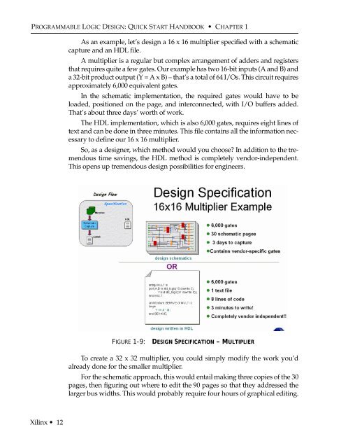
As an example, let’s design a 16 x 16 multiplier specified with a schematic<br />
capture and an HDL file.<br />
A multiplier is a regular but complex arrangement of adders and registers<br />
that requires quite a few gates. Our example has two 16-bit inputs (A and B) and<br />
a 32-bit product output (Y = A x B) – that’s a total of 64 I/Os. This circuit requires<br />
approximately 6,000 equivalent gates.<br />
In the schematic implementation, the required gates would have to be<br />
loaded, positioned on the page, and interconnected, with I/O buffers added.<br />
That’s about three days’ worth of work.<br />
The HDL implementation, which is also 6,000 gates, requires eight lines of<br />
text and can be done in three minutes. This file contains all the information necessary<br />
to define our 16 x 16 multiplier.<br />
So, as a designer, which method would you choose In addition to the tremendous<br />
time savings, the HDL method is completely vendor-independent.<br />
This opens up tremendous design possibilities for engineers.<br />
FIGURE 1-9:<br />
DESIGN SPECIFICATION – MULTIPLIER<br />
To create a 32 x 32 multiplier, you could simply modify the work you’d<br />
already done for the smaller multiplier.<br />
For the schematic approach, this would entail making three copies of the 30<br />
pages, then figuring out where to edit the 90 pages so that they addressed the<br />
larger bus widths. This would probably require four hours of graphical editing.<br />
Xilinx • 12


