I-682 Refrigerant Transmitter Installation, Operation and ... - Brasch
I-682 Refrigerant Transmitter Installation, Operation and ... - Brasch
I-682 Refrigerant Transmitter Installation, Operation and ... - Brasch

You also want an ePaper? Increase the reach of your titles
YUMPU automatically turns print PDFs into web optimized ePapers that Google loves.
<strong>Installation</strong>, Operating<br />
And<br />
Maintenance Instructions<br />
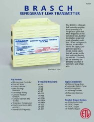
<strong>Refrigerant</strong><br />
Gas <strong>Transmitter</strong><br />
BGS-RF-TRNS<br />
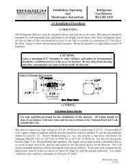
1.0 <strong>Installation</strong> Procedures<br />
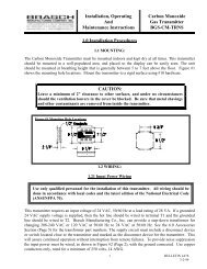
1.1 MOUNTING:<br />
The <strong>Refrigerant</strong> <strong>Transmitter</strong> must be mounted indoors <strong>and</strong> kept dry at all times. This transmitter should<br />
be mounted in a well-populated area, <strong>and</strong> placed so the display can be easily seen. Since refrigerant<br />
vapors are heavier than air, this unit should be as close to the floor as possible at a maximum of 5 Feet<br />
above the floor. Figure #1 shows the mounting hole locations. Mount the transmitter to a rigid surface<br />
using #10 hardware.<br />
CAUTION:<br />
Leave a minimum of 2” clearance to other surfaces, <strong>and</strong> under no circumstances<br />
should the ventilation louvers in the cover be blocked. Be sure that metal shavings<br />
<strong>and</strong> other contaminants are removed from inside the transmitter.<br />
Figure #1 Mounting Hole Locations<br />
1.2 WIRING:<br />
1.21 Input Power Wiring<br />
Use only qualified personnel for the installation of this transmitter. All wiring should be<br />
done in accordance with local codes <strong>and</strong> the latest edition of the National Electrical Code<br />
(ANSI/NFPA 70).<br />
This transmitter requires an input voltage of 24 VAC, 50/60 Hz at a load rating of 28 VA. If a grounded<br />
24 VAC supply voltage is supplied, then the hot line should be wired to terminal T1 <strong>and</strong> the grounded<br />
line should be wired to T2. <strong>Brasch</strong> Manufacturing Co., Inc. can provide a step-down transformer for<br />
changing 208-240 VAC or 120 VAC at 50/60 Hz to 24 VAC at 50/60 Hz. See the 6.0 Accessories<br />
Section (Page 5) for the transformer part numbers. The supply circuit must include a disconnect device<br />
or switch located close to the transmitter <strong>and</strong> marked as the disconnect device for the transmitter. This<br />
will assure continued operation without interruption from remote failures. To provide noise suppression<br />
the input power must be wired, as shown in Figure #2 (Page 2), with the ground connected. Use copper<br />
conductors only, rated for a minimum of 250 volts, 14 AWG.<br />
1<br />
BULLETIN I-<strong>682</strong><br />
3-2-99
Figure #2 Input Power Wiring<br />
Figure #3 Proportional Output Wiring<br />
1.22 Proportional Output Wiring<br />
See the 4.0 Specification Section (Page 4)<br />
for minimum/maximum loads for the<br />
proportional outputs. The wiring of the<br />
proportional output signals is done by<br />
lifting the white lever, inserting the signal<br />
wire <strong>and</strong> pressing the white lever flat. Use<br />
copper conductors only, rated for a<br />
minimum of 250 volts, with a minimum<br />
wire size of 26 AWG (22 AWG<br />
maximum). Figure #3, Proportional<br />
Output Wiring shows the wiring to a<br />
remote <strong>Brasch</strong> Gas Detector Control<br />
Panel, DDCS or BMS.<br />
2.0 Unit <strong>Operation</strong><br />
The <strong>Refrigerant</strong> Gas <strong>Transmitter</strong> can sense any one of twelve refrigerant gases. Any of the following are<br />
available; R-11, R-12, R-22, R-23, R-113, R-123, R-134a, R-141b, R-142b, R-152a, R-500 or R-502.<br />
Each <strong>Refrigerant</strong> gas transmitter is calibrated for one of these gases <strong>and</strong> an identifying sticker is placed<br />
on the front cover of the unit. Changing the calibration refrigerant will require a new factory calibration.<br />
When power is applied to the <strong>Refrigerant</strong> Gas <strong>Transmitter</strong> the internal green power LED will illuminate.<br />
This LED will stay ON as long as power is supplied to the transmitter. If the power ON LED should go<br />
out, see the 5.0 Troubleshooting Section (Page 4) for help.<br />
This <strong>Refrigerant</strong> Gas <strong>Transmitter</strong> has three modes of operation (Normal, Sensor Failure <strong>and</strong> Purge).<br />
Upon the application of power the unit will enter the Purge mode <strong>and</strong> remain in this mode for 5 minutes.<br />
In the Purge mode the internal green power LED illuminates <strong>and</strong> the internal yellow sensor LED will<br />
flash on <strong>and</strong> off. In this mode the gas transmitter cleans <strong>and</strong> prepares the sensor for operation. Upon the<br />
completion of this mode the transmitter will turn off the yellow sensor indicator entering the Normal<br />
mode.<br />
In the Normal mode the transmitter monitors the concentration of refrigerant <strong>and</strong> generates the<br />
proportional output signal.<br />
BULLETIN I-<strong>682</strong><br />
3-2-99<br />
2
An additional safety feature of the transmitter is a continual internal sensor test. Should something cause<br />
the sensor to malfunction the transmitter will enter the Sensor Failure mode. Upon entering this mode<br />
the transmitter will turn on the internal yellow sensor LED <strong>and</strong> generate a 0 proportional output signal.<br />
3.0 <strong>Operation</strong>al Settings<br />
3.1 PROPORTIONAL OUTPUT OPTIONS<br />
The gas transmitter has four different proportional output options that are selectable on the transmitter<br />
board. The four options are 4 – 20 maDC current loop, 0 – 1 VDC voltage output, 0 – 5 VDC voltage<br />
output <strong>and</strong> 0 – 10 VDC voltage output. The 4 – 20 maDC current loop is used with the <strong>Brasch</strong> Gas<br />
Detector Control Panel. Any of the four options can be connected to a Direct Digital Control System<br />
(DDCS) or Building Management System (BMS). See 4.0 the Specification Section (Page 4) for the<br />
input impedance for each of the proportional outputs.<br />
The output option is selected using a jumper <strong>and</strong> pin combination. See Figure #4 for location on the<br />
transmitter board. To change the setting, turn off the power to the unit <strong>and</strong> remove the cover. Place<br />
jumpers in the proper locations for the desired proportional output. Replace the cover <strong>and</strong> restore power<br />
to the transmitter.<br />
Figure #4 Selection of Proportional Output Option<br />
The proportional output is<br />
controlled by the concentration of<br />
refrigerant (See Table #1). If at<br />
any time a value of 0 maDC or 0<br />
VDC is measured at the output,<br />
the gas transmitter has had a<br />
power or sensor failure (See 5.0<br />
Troubleshooting, Page 4).<br />
TABLE #1 Proportional Output Values<br />
<strong>Refrigerant</strong> PPM<br />
4 – 20 maDC<br />
Output Level<br />
0 – 1 VDC<br />
Output Level<br />
0 – 5 VDC<br />
Output Level<br />
0 – 10 VDC<br />
Output Level<br />
0 4.0 0.20 1.0 2.0<br />
80 5.6 0.28 1.4 2.8<br />
160 7.2 0.36 1.8 3.6<br />
240 8.8 0.44 2.2 4.4<br />
320 10.4 0.52 2.6 5.2<br />
400 12.0 0.60 3.0 6.0<br />
480 13.6 0.68 3.4 6.8<br />
560 15.2 0.76 3.8 7.6<br />
640 16.8 0.84 4.2 8.4<br />
720 18.4 0.92 4.6 9.2<br />
800 20.0 1.00 5.0 10.0<br />
3<br />
BULLETIN I-<strong>682</strong><br />
3-2-99
4.0 Specifications<br />
Proportional Outputs: 4 – 20 maDC 250Ω Maximum<br />
0 – 1 VDC 1000Ω Minimum<br />
0 – 5 VDC 1000Ω Minimum<br />
0 – 10 VDC 1000Ω Minimum<br />
Proportional outputs are field selectable.<br />
Calibration:<br />
The main transmitter module should be re-calibrated every three years.<br />
Contact the factory for re-calibration including new sensor.<br />
Ratings: Input Power: 24 VAC, 50/60 Hz, 28 VA<br />
Humidity: 10% to 90% (Non-Condensing)<br />
Temperature: Storage: -50 o C to 120 o C (-58 o F to 248 o F)<br />
Operating: -15 o C to 40 o C (5 o F to 104 o F)<br />
<strong>Installation</strong> Category:<br />
II (local level, over-voltage transients less than 500 volts)<br />
Indicators(LED Type): Green LED: Power ON<br />
Yellow LED: Sensor Failure<br />
Dimensions:<br />
Weight:<br />
7 5/8”H x 9 1/8”W x 2 1/4”D<br />
4 pounds<br />
Fuse Rating: Main Supply: 5x20MM, Time-Lag, 1.25 Amps<br />
5.0 Troubleshooting<br />
CAUTION:<br />
Only qualified personnel should attempt to service this equipment. All power<br />
sources must be disconnected before removing the cover of this transmitter.<br />
1. Power LED not on: A. Check for 20.4-26.4 VAC at terminals T1 & T2 (see Figure #2,<br />
Page 2).<br />
B. Check circuit board fuse for continuity. If the fuse needs to be<br />
replaced use only the rated fuse listed in the 4.0 Specifications<br />
Section.<br />
C. Consult the factory.<br />
2. Sensor failure light is on: A. Remove sensor <strong>and</strong> reinstall noting correct terminal markings.<br />
B. Replace transmitter board (includes sensor <strong>and</strong> calibration).<br />
C. Consult the factory.<br />
3. For any other situation please consult the factory.<br />
BULLETIN I-<strong>682</strong><br />
3-2-99<br />
4
6.0 Accessories<br />
Transformers:*<br />
120 VAC to 24 VAC @ 36VA 36T120N1<br />
120 VAC to 24 VAC @ 75VA 75T120N1<br />
208-240 VAC to 24 VAC @ 36VA 36T240N1<br />
208-240 VAC to 24 VAC @ 75VA 75T240N1<br />
Other voltage levels are available upon request.<br />
* Transformers supplied in a NEMA 1 enclosure intended for indoor use.<br />
Sensor Re-calibration: Factory re-calibration of transmitter board including new sensor.<br />
Contact the factory for complete information <strong>and</strong> pricing.<br />
Limited Warranty<br />
<strong>Brasch</strong> Manufacturing Co., Inc warrants gas transmitters, gas detectors,<br />
gas detector control panels <strong>and</strong> accessories for a period of one year<br />
from the date of shipment against defects in material or workmanship.<br />
Should any evidence of defects in material or workmanship occur<br />
during the warranty period, <strong>Brasch</strong> Manufacturing Co., Inc will repair<br />
or replace at its own discretion, without charge. The company shall not<br />
be held responsible for any charges in connection with removal or<br />
replacement of allegedly defective equipment, nor for incidental or<br />
consequential damages.<br />
<strong>Brasch</strong> Manufacturing Company, Inc.<br />
2310 Millpark Drive<br />
Maryl<strong>and</strong> Heights, MO 63043<br />
(314)291-0440<br />
fax: (314)291-0646<br />
5<br />
BULLETIN I-<strong>682</strong><br />
3-2-99