PS2 AC and DC Installation Instructions (979 KB PDF)
PS2 AC and DC Installation Instructions (979 KB PDF)
PS2 AC and DC Installation Instructions (979 KB PDF)

You also want an ePaper? Increase the reach of your titles
YUMPU automatically turns print PDFs into web optimized ePapers that Google loves.
<strong>PS2</strong><strong>AC</strong> & <strong>DC</strong><br />
INSTALLATION INSTRUCTIONS<br />
19009 62 nd Ave. NE Arlington, WA 98223<br />
Phone (360) 435-6030 Fax (360) 435-6019<br />
www.outbackpower.com<br />
REV G 9-30-04<br />
900-003-1
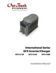
<strong>PS2</strong><strong>AC</strong> & <strong>DC</strong> INSTRUCTIONS<br />
The <strong>PS2</strong><strong>AC</strong> & <strong>DC</strong> come st<strong>and</strong>ard with an impressive array of components that form the basis for your<br />
Renewable Energy system. Additional components may be required to customize the system to your<br />
specific application.<br />
STANDARD FEATURES<br />
<strong>PS2</strong><strong>AC</strong> COMPONENTS<br />
• Dual 50A bypass switch (no de-rating required).<br />
• Dual 50A breaker for inverter <strong>AC</strong> input (charger + pass through).<br />
• 1 15A load circuit breaker for the <strong>AC</strong> outlet.<br />
• 1 20A circuit breaker for house loads.<br />
• 2 BL<strong>AC</strong>K insulated bus bars for Hot <strong>AC</strong> IN <strong>and</strong> OUT leg1.<br />
• 2 RED insulated bus bars for Hot <strong>AC</strong> IN <strong>and</strong> OUT leg 2.<br />
• 1 WHITE insulated bus bar for <strong>AC</strong> Neutral in <strong>and</strong> out.<br />
• 1 GROUND bus bar bonded to cabinet.<br />
• Knockouts for 8 additional OutBack style <strong>AC</strong> load breakers.<br />
• 14 AWG wires for the include <strong>AC</strong> outlet / Outlet is a st<strong>and</strong>ard duplex outlet <strong>and</strong> not suitable for<br />
areas that require a Ground Fault Circuit Interrupter (GFCI) outlet.<br />
• 6 AWG red, black <strong>and</strong> white wires for the inverter input, output <strong>and</strong> bypass hook-up.<br />
• Provisions for mounting an X-240 (requires 2 of the additional <strong>AC</strong> breaker spaces).<br />
• Knockouts on five surfaces to facilitate conduit <strong>and</strong> inverter hook-up.<br />
<strong>PS2</strong><strong>DC</strong> COMPONENTS<br />
• 1or 2 inverter battery circuit breakers. 250A for 3524’s, 2812’s, 2012T’s / 175A for 2024’s,<br />
3648’s <strong>and</strong> 2524’s / 100A for FX2548’s <strong>and</strong> 3048’s.<br />
• 500A shunt for hookup to Tri-metric, E-meter, Trace Meter or OutBack smart shunt.<br />
• Battery Negative / Ground bus bar (configurable for OB/GFP-2 ground installation).<br />
• RED <strong>DC</strong> Positive bus bar with three 1/0 holes <strong>and</strong> nine 6AWG holes.<br />
• Mounting brackets for MX-60 <strong>and</strong> MATE.<br />
• Knockouts for eight ¾” wide <strong>DC</strong> breakers.<br />
• Knockouts to facilitate battery conduit, MX-60 interconnect, stacking another <strong>PS2</strong> etc.<br />
• Bus bar for adding another inverter battery breaker.<br />
ADDITIONAL COMPONENTS IN THE <strong>PS2</strong> SYSTEM<br />
• <strong>PS2</strong>MP mounting plate.<br />
• 1 or 2 OutBack FX Inverters (Sealed or Vented).<br />
• <strong>DC</strong>C Inverter cover for vented inverters or FX Turbo for sealed inverters<br />
• <strong>DC</strong>A Adaptor<br />
• <strong>AC</strong>A Adaptor<br />
OPTIONAL FEATURES<br />
• Hub4 for stacking <strong>and</strong> communications.<br />
• Mate or Mate2 for status <strong>and</strong> programming<br />
• MX60 for solar charge control.<br />
• X-240 Autoformer allows the series 120/240 system to divert all of the inverter power to either leg<br />
as required for surge loads <strong>and</strong> ½ power for continuous loads.<br />
• Additional <strong>AC</strong> <strong>and</strong> <strong>DC</strong> breakers<br />
• RTS (remote temperature sensor)<br />
Copyright OutBack Power Systems www.outbackpower.com REV G 900-003-1
<strong>PS2</strong><strong>AC</strong> & <strong>DC</strong> INSTRUCTIONS<br />
MOUNTING PLATE INSTRUCTIONS<br />
1. Determine the desired height of the<br />
assembly. Generally the height of<br />
assembly is arbitrary. However, if a<br />
battery storage box such as the OutBack<br />
PSR to be placed below the <strong>PS2</strong> system,<br />
the bottom of the mounting plate<br />
(<strong>PS2</strong>MP) should be between 44” <strong>and</strong> 46”<br />
off the ground. The PSR is 42 inches<br />
high. Connection between the <strong>PS2</strong> <strong>and</strong><br />
PSR is made via a 3” or 6” long conduit<br />
nipple (2” diameter). The <strong>PS2</strong><strong>DC</strong> bottom<br />
knockouts are located to match up with<br />
the PSR top knockouts. Figure 1 shows<br />
the dimensions of the PSR <strong>and</strong> <strong>PS2</strong><br />
Figure 1 <strong>PS2</strong> System Dimensions (inches)<br />
system. If you are not using a <strong>PS2</strong>MP,<br />
but you will be using an X-240<br />
Autoformer, you must mount the X-240 to<br />
the <strong>PS2</strong><strong>AC</strong> before you assemble the rest of the system.<br />
<strong>PS2</strong><br />
2” (dia.)<br />
Conduit Nipple<br />
PSR<br />
2. Use four (4) 5/16” bolts (2 on top <strong>and</strong> 2 on bottom) to<br />
secure the mounting plate to 2x4 studs. Make sure<br />
the “T” is in the top left corner (Figure 2). You will<br />
be very unhappy with yourself if you install it all <strong>and</strong><br />
the “T” is in the bottom right corner. When mounting<br />
to other than a 2x4 or 2x6 wall make sure the structure<br />
is adequate to hold 250 pounds.<br />
Figure 2 Make sure the 'T' is on the<br />
upper left corner<br />
ATT<strong>AC</strong>HING THE <strong>PS2</strong><strong>AC</strong> & <strong>DC</strong> ONTO THE MOUNTING PLATE<br />
1. Locate all extruded funnel holes on the mounting plate that you will be using to mount the<br />
<strong>PS2</strong><strong>DC</strong>, <strong>AC</strong> <strong>and</strong> FX’s. Pre-tap these holes using 6mm self-tapping (TAPTITE®) screws <strong>and</strong> a #3<br />
Phillips tip bit in a drill. It is much easier to do this now rather than when installing the<br />
equipment.<br />
2. Mount the <strong>PS2</strong><strong>AC</strong> cabinet <strong>and</strong> the <strong>PS2</strong><strong>DC</strong> cabinet. For each cabinet, use six 6mm x 10mm pan<br />
head Phillips TAPTITE® screws <strong>and</strong> one star washer (included in hardware packet). At least one<br />
mounting screw from both the <strong>PS2</strong><strong>AC</strong> <strong>and</strong> the <strong>PS2</strong><strong>DC</strong> must have a star washer to bite through the<br />
powder coating <strong>and</strong> connect to ground. The washers ensure that all the equipment is grounded to<br />
the mounting plate. Placing a star washer under each screw will improve your lightning<br />
protection.<br />
3. Determine the knock-outs you will use to run wires between the FX cabinets. Use a screwdriver<br />
to wiggle them free from the housings.<br />
4. Leave all mounting screws loose until all 2 ½”snap in bushings <strong>and</strong> the FX adapters (<strong>AC</strong>A &<br />
<strong>DC</strong>A) are installed between the <strong>PS2</strong><strong>AC</strong> <strong>and</strong> the <strong>PS2</strong><strong>DC</strong>.<br />
Copyright OutBack Power Systems www.outbackpower.com REV G 900-003-1
<strong>PS2</strong><strong>AC</strong> & <strong>DC</strong> INSTRUCTIONS<br />
Figure 3 <strong>PS2</strong><strong>AC</strong> (left) <strong>and</strong> <strong>PS2</strong><strong>DC</strong> (right) screw type <strong>and</strong> placement.<br />
INSTRUCTIONS FOR MOUNTING AN FX<br />
1. Make sure the extruded funnel holes have been pre-tapped with 6mm screws <strong>and</strong> a #3 Phillips<br />
tip bit in a drill.<br />
2. Mount the FX inverter(s) using four (4) 6mm x 20mm pan head Phillips TAPTITE® screws<br />
(all hardware is provided in the hardware pack). For illustration see Figure 4. Once again, at<br />
least one screw must have a star washer to insure it bites through the powder coating. This is<br />
your equipment bonding <strong>and</strong> meets NEC code requirements for equipment bonding. Use four<br />
star washers for improved lightning protection.<br />
3. Do not install the large FX <strong>DC</strong>C cover at this time. Figure 4 shows FX with cover installed.<br />
4. If you are installing a turbo kit instead of the usual <strong>DC</strong>C (<strong>DC</strong> Cover), mount the <strong>DC</strong>A (Figure<br />
5) with the two (2) M5 x 12mm screws provided. Normally, the screws for the <strong>DC</strong>C will hold<br />
down the <strong>DC</strong>A as well.<br />
5. Install the <strong>AC</strong>A adapter (Figure 5) using two (2) M5 x 20mm screws inside the <strong>AC</strong>A <strong>and</strong> two<br />
(2) #10 x 3/8” screws outside the <strong>AC</strong>A. You must first remove the two chassis screws using a<br />
4mm hex wrench.<br />
6. Cut the 2 ½” circle out of the plastic FX-<strong>AC</strong>A with a sharp knife (Figure 6). Do not attempt<br />
to push or knock out the circle because the plastic will crack.<br />
7. Install the snap in bushings (Figure 7).<br />
Figure 4 Use four (4) 6mm x 20mm Pan Head Philips TAPTITE® screws.<br />
Copyright OutBack Power Systems www.outbackpower.com REV G 900-003-1
<strong>PS2</strong><strong>AC</strong> & <strong>DC</strong> INSTRUCTIONS<br />
FX NOTE: It is highly recommended to have the Turbo kit installed on the sealed FX series of inverters.<br />
The Turbo kit adds up to 500 watts additional continuous power to each FX inverter <strong>and</strong> insures full<br />
charging in high temperature conditions. No external fan is required on installations using vented<br />
versions of the FX inverter.<br />
Figure 5 FX <strong>AC</strong>A (left) <strong>and</strong> <strong>DC</strong>A (right).<br />
Figure 6. Cut the 2 ½” circle out of the<br />
plastic FX-<strong>AC</strong>AS.<br />
Figure 7 Snap in bushings<br />
Copyright OutBack Power Systems www.outbackpower.com REV G 900-003-1
<strong>PS2</strong><strong>AC</strong> & <strong>DC</strong> INSTRUCTIONS<br />
MOUNTING THE HUB<br />
Mount the HUB using two (2) #10 x 3/8” Phil PH screws. Figure 8 shows<br />
placement of the Hub4. Don’t forget to use the plastic bushings in the cabling holes.<br />
The old guy in the picture is me.<br />
Figure 8 Placement of<br />
HUB.<br />
WIRING THE <strong>PS2</strong><strong>AC</strong><br />
All equipment should now be mounted to the <strong>PS2</strong>MP mounting plate. If all<br />
bushings are in place, then tighten all screws. It is now time to wire the<br />
equipment. Before you connect any wires, make sure all the breakers are off.<br />
The <strong>DC</strong> box does not come with any wires or cables. The following is a list of<br />
supplied wires <strong>and</strong> their function in the <strong>PS2</strong><strong>AC</strong>. Additional wiring may be<br />
required to complete your particular system. You will not use all of these wires<br />
if only one FX is being installed. Figure 10 is a diagram of where wires<br />
connect. Identical diagrams are on the insides of the cabinet covers.<br />
Qty Awg/Len. Color Function<br />
2 6/22” Black <strong>AC</strong> Out Hot Leg1 Bus bar to left Bypass breaker top & left Inv output<br />
breaker top.<br />
1 6/14” Black <strong>AC</strong> In Hot Leg 1 Bus bar to left Bypass breaker bottom<br />
1 6/12” Black <strong>AC</strong> In Hot Leg 1 Bus bar to left Inv Input breaker bottom<br />
2 6/20” Red <strong>AC</strong> Out Hot Leg 2 Bus bar to right Bypass breaker top & right Inv Output<br />
breaker top<br />
1 6/16” Black Upper Inverter <strong>AC</strong> Hot In terminal to left Inverter Input breaker top<br />
1 6/20.5” Red Lower Inverter <strong>AC</strong> Hot In terminal to right Inverter Input<br />
breaker top<br />
2 6/12” Red <strong>AC</strong> In Hot Leg 2, Bus bar to right Bypass breaker, bottom & right Inverter<br />
Input breaker bottom.<br />
1 6/12.5” White Upper Inverter <strong>AC</strong> Neutral In terminal to <strong>AC</strong> Neutral Bus<br />
1 6/21” White Lower Inverter <strong>AC</strong> Neutral In terminal to <strong>AC</strong> Neutral Bus<br />
1 6/27.5” Black Upper Inverter <strong>AC</strong> Hot Out terminal to left Inv Output breaker bottom<br />
1 6/17” Red Lower Inverter <strong>AC</strong> Hot Out terminal to right Inv Output breaker bottom<br />
1 14/17” Green <strong>AC</strong> outlet Ground-to-Ground Bus bar<br />
1 14/18.75”Black <strong>AC</strong> Duplex Outlet Hot (brass screw) to 15A breaker top<br />
1 14/25.75” White <strong>AC</strong> Duplex Outlet Neutral (silver screw) to Neutral Bus Bar<br />
1 14/13.00” Black 15A breaker bottom to <strong>AC</strong> out Leg 1 Bus bar<br />
Copyright OutBack Power Systems www.outbackpower.com REV G 900-003-1
<strong>PS2</strong><strong>AC</strong> & <strong>DC</strong> INSTRUCTIONS<br />
<strong>AC</strong> breakers are available in 15A single &dual, 20A, 25A & 30A dual, 50A single <strong>and</strong> dual<br />
configurations (example: OB<strong>AC</strong>15). The <strong>PS2</strong><strong>AC</strong> will accommodate 8 additional breakers spaces.<br />
The small 125V<strong>DC</strong> breakers for the <strong>PS2</strong><strong>DC</strong> are available in 1A, 5A, 10A, 15A, 20A, 30A, 40A, 50A,<br />
60A, 70A, <strong>and</strong> 80A configurations (example: OB<strong>DC</strong>-15). The big battery breakers are available in 100A<br />
<strong>and</strong> 125A (1” wide), <strong>and</strong> 175A or 250A (1.5” wide) versions. The FX 2024, GTFX25424, GVFX3648<br />
<strong>and</strong> VFX3648 require 175A breakers (OB<strong>DC</strong>-175), while the FX2548 requires a 100A breaker (OB<strong>DC</strong>-<br />
100). The GTFX3048 can use either the 100A or the 125A 1” wide breaker. The FX2012, VFX2812,<br />
GVFX3524 <strong>and</strong> VFX3524 require 250A breakers. The <strong>PS2</strong><strong>DC</strong> will accept up to 2 of the 1.5” breakers or<br />
3 of the 1” wide battery breakers. There are 8 slots for ¾” wide <strong>DC</strong> breakers.<br />
Use a flat tip screw driver to tighten the wires in the <strong>AC</strong> breakers to a torque of twenty (20) inch-pounds.<br />
Twenty is quite a lot of torque when you are attempting to hold the breaker from moving. The wires will<br />
loosen up afterwards if not properly torqued so pay attention to this one <strong>and</strong> recheck tightness after an hour.<br />
Don’t use a Phillips head screw driver, you may not be able to torque the screws down without stripping<br />
them.<br />
Figure 9 Picture of <strong>PS2</strong><strong>AC</strong> wired with a fairly full compliment of breakers<br />
Copyright OutBack Power Systems www.outbackpower.com REV G 900-003-1
BYPASS<br />
<strong>PS2</strong><strong>AC</strong> & <strong>DC</strong> INSTRUCTIONS<br />
SHOWN ARE: F<strong>AC</strong>TORY INSTALLED PARTS, OPTIONS AND USER INSTALLED PARTS.<br />
<strong>PS2</strong><strong>AC</strong><br />
19 MX60 20<br />
#4<br />
L1<br />
X-240<br />
#2&3<br />
N<br />
#1<br />
L2<br />
ADD NEU/GND BOND<br />
WIRE WHEN USING<br />
<strong>PS2</strong><strong>AC</strong> AS LOAD<br />
CENTER<br />
120/240V<strong>AC</strong><br />
LOADS<br />
<strong>AC</strong> OUT<br />
<strong>AC</strong> IN<br />
PV+<br />
NORMAL<br />
50A 50A 50A 50A 50A 50A 25A 25A 15A 20A 15A 15A 15A 15A 15A 15A<br />
OUT<br />
X-240 HOUSE LOADS<br />
BYPASS OUTPUT INPUT LET ALL GNDS<br />
ARE BONDED<br />
TO THE B<strong>AC</strong>K<br />
PLATE THRU<br />
THE MOUNT-<br />
ING SCREWS<br />
<strong>AC</strong> OUT<br />
SHOWN WITH PV & BAT NEGATIVES<br />
INTERNALLY CONNECTED TOGETHER<br />
HUB 4 OR 10<br />
FX SERIES<br />
B+<br />
B-<br />
MATE<br />
B- PV-<br />
B+ PV+<br />
PV-<br />
PV+<br />
60A<br />
60A<br />
60A<br />
.5A<br />
OB<strong>DC</strong>-GFP/2<br />
GND<br />
ROD<br />
PV+<br />
<strong>AC</strong> IN<br />
<strong>AC</strong> IN LEG 1<br />
<strong>AC</strong> IN LEG 2<br />
<strong>AC</strong> OUT LEG 1<br />
<strong>AC</strong> OUT LEG 2<br />
120V<strong>AC</strong> X-FAN<br />
(GENERATORS)<br />
120/240V<strong>AC</strong><br />
GROUND<br />
<strong>DC</strong> POSITIVE<br />
AS BUILT CONFIGURATION<br />
NEUTRAL<br />
No.<br />
QTY<br />
11<br />
10<br />
9 1 2 3 4 5 6 7 8<br />
18<br />
17<br />
STANDARD<br />
FX SERIES<br />
16<br />
15<br />
21 22<br />
100A 100A<br />
60A 60A 60A 175A 175A<br />
250A 250A<br />
23 24 25<br />
26 27<br />
COPPER<br />
BUS<br />
12<br />
<strong>AC</strong> SOURCE<br />
GENERATOR<br />
OR GRID<br />
<strong>AC</strong> SUB-PANEL<br />
13<br />
14<br />
RTS<br />
BATTERIES<br />
TURBO<br />
ON BOTH<br />
INVERTERS<br />
<strong>PS2</strong><strong>DC</strong><br />
<strong>PS2</strong> SYSTEM<br />
Figure 10 <strong>PS2</strong> Wiring Diagram<br />
Copyright OutBack Power Systems www.outbackpower.com REV G 900-003-1
<strong>PS2</strong><strong>AC</strong> & <strong>DC</strong> INSTRUCTIONS<br />
X-240 AUTOFORMER OPTION FOR<br />
<strong>PS2</strong><strong>AC</strong><br />
See the X-240 manual for installation. When<br />
the X-240 Autoformer is installed, run the<br />
Autoformer wires #1(red) <strong>and</strong> #4 (black) into<br />
the top of the 25A breaker provided.<br />
Autoformer wires #2 <strong>and</strong> #3 go to the neutral<br />
buss bar. Just as you have with all leg 1 <strong>and</strong> leg<br />
2 wires in the box, keep black on the left <strong>and</strong><br />
red on the right. Use 10AWG wire to connect<br />
up the bottom of the X-240 breakers to the Hot<br />
Out Leg 1 & 2 Bus bars. The red wire should be<br />
18” <strong>and</strong> the black wire 12”. These wires are not<br />
supplied with the <strong>PS2</strong><strong>AC</strong>.<br />
Figure 11 Installed X-240<br />
Figure 12. X-240 current flow for normal (left) <strong>and</strong> surge (right) operation<br />
Figure 12 shows the current flow when an X-240 is used as an Autoformer under both normal <strong>and</strong><br />
surge conditions. The X-240 balances the loads between the two legs. In this case, each inverter is<br />
capable of generating 2500W. The load on leg 1 is not consuming all of the power generated by<br />
inverter 1, but the load on leg two is greater than 2500W. One example of this type of situation is<br />
when a well pump kicks in, requiring large amounts of power on one leg. That situation is shown in<br />
the surge diagram (right). The Autoformer balances the power, allowing the excess power from leg 1<br />
to be utilized by leg 2.<br />
Copyright OutBack Power Systems www.outbackpower.com REV G 900-003-1
<strong>PS2</strong><strong>AC</strong> & <strong>DC</strong> INSTRUCTIONS<br />
WIRING THE <strong>PS2</strong><strong>DC</strong><br />
Use 2/0 cable to connect the <strong>DC</strong> terminals of the FX’s if using 100A, 125A or 175A battery breakers. Use<br />
4/0 for systems requiring 250A breakers. The following is the proper length to cut your cable:<br />
Top FX negative terminal (black) 30”<br />
Top FX positive terminal (red) 23”<br />
Bottom FX negative terminal 26”<br />
Bottom FX positive terminal 29”<br />
OutBack now has battery cable heat shrink with our<br />
logo on it (Figure 13). Ask your dealer for this<br />
special heat shrink to jazz your installation up a bit.<br />
When two inverters are mounted, you will need at<br />
least 4/0 cable from the <strong>PS2</strong><strong>DC</strong> to the batteries.<br />
FX’s using 250A breakers should use 4/0 to each<br />
unit throughout the <strong>DC</strong> wiring. Check the inverter<br />
manual for proper wire sizing. Note: The inverter<br />
negative wires should go to the right h<strong>and</strong> side of<br />
the shunt (Figure 14).<br />
BATTERY BUS<br />
POSITIVE BUS<br />
Figure 14 Inverter negative wired to the<br />
correct (right) side of the shunt<br />
Figure 13 OutBack Heat Shrink<br />
Figure 14 shows the inverter negatives wired to the<br />
correct side of the shunt. Also note how the Plus bus<br />
is wired to the battery bus. Figure 15 shows the<br />
inverter wiring with FX-<strong>AC</strong>A <strong>and</strong> FX-<strong>DC</strong>A<br />
installed. The FX-<strong>DC</strong>C cover is removed to show<br />
wiring. Note that the MATE <strong>and</strong> RTS wires both go<br />
to the <strong>DC</strong> end. You will need to notch out the Lexan<br />
cover a bit to accommodate this. The RTS by itself<br />
will fit without cutting or filing, but not the cat5<br />
cable. The Lexan cover is not brittle <strong>and</strong> will not<br />
split or crack so notch away.<br />
Figure 15 Inverter wiring without <strong>DC</strong>C.<br />
Copyright OutBack Power Systems www.outbackpower.com REV G 900-003-1
<strong>PS2</strong><strong>AC</strong> & <strong>DC</strong> INSTRUCTIONS<br />
WIRING THE MX60<br />
Mount the Mate <strong>and</strong> MX60 brackets to the side of the <strong>PS2</strong><strong>DC</strong> (Figure 16). The MX60 wiring goes<br />
through a 1” nipple between the MX60 <strong>and</strong> the <strong>PS2</strong><strong>DC</strong> (Figure 17. One wire protector is missing,<br />
probably because it was wired by an OutBack engineer). You can also use the 1” snap in bushing supplied<br />
with the <strong>PS2</strong><strong>DC</strong> instead of the nipple. If you use the plastic bushing, you must ground the MX60 to the<br />
<strong>PS2</strong><strong>DC</strong> using star washers.<br />
1. Connect a RED 6 AWG wire between the MX60 PV+ <strong>and</strong> the breaker labeled MX60 #1 PV IN.<br />
The other side of the breaker gets tied to the PV+ in the <strong>PS2</strong><strong>DC</strong> box. Figure 18 shows where all<br />
the wires from the MX 60 go.<br />
2. Connect the MX60 PV- to the <strong>DC</strong> NEGATIVE bus bar in the <strong>PS2</strong><strong>DC</strong>. The PV- from the PV array<br />
also connects to the negative bus bar.<br />
3. Connect the MX60’s BAT+ terminal to the MX60#2 BATTERY breaker. The other end of the<br />
breaker connects to the <strong>DC</strong> POSITIVE bus bar.<br />
4. Connect the MX60’s BAT- terminal to the <strong>DC</strong> NEGATIVE bus bar.<br />
Figure 16. Brackets for MATE & MX60 (left) & lower 4<br />
screw positions for MX60 (right).<br />
Figure 17 MX-60 Wiring<br />
Figure 16. MX60 Wiring Diagram<br />
Copyright OutBack Power Systems www.outbackpower.com REV G 900-003-1
<strong>PS2</strong><strong>AC</strong> & <strong>DC</strong> INSTRUCTIONS<br />
Figure 19 Placement <strong>and</strong> mounting position for MX60 <strong>and</strong> MATE. Snap in the 1-3/8" bushing to protect the<br />
wiring that runs between the <strong>PS2</strong><strong>DC</strong> <strong>and</strong> the MX60.<br />
WIRING THE MATE & HUB<br />
1. Connect the MATE’s CAT-5 network cable from the MATE to the HUB’s MATE1 port (Figure 20).<br />
2. Connect the FX inverter CAT-5 cable(s) to port 1 (<strong>and</strong> port 2 if there are two inverters).<br />
Figure 19shows where to connect the inverters <strong>and</strong> the MATE. If only one inverter is being used, connect it into<br />
hub port 1. The CAT-5 cables are covered up by the plastic cover in the right picture. Don’t forget to use the<br />
plastic bushings in the cabling holes. The master inverter must be connected into port 1.<br />
Figure 20 Mounted HUB with cover (left) & HUB connected to 2 inverters<br />
(right). The far right arrow shows where the MATE connects.<br />
Copyright OutBack Power Systems www.outbackpower.com REV G 900-003-1
<strong>PS2</strong><strong>AC</strong> & <strong>DC</strong> INSTRUCTIONS<br />
CONNECTING EXTERNAL COMPONENTS<br />
Now that you have your <strong>PS2</strong> system all wired up, it’s time to make it work. That means hooking up the<br />
batteries, PV panels, <strong>and</strong> any loads you have. This is where you will start if you were wise <strong>and</strong> purchased a prewired<br />
system. Figure 21 (on the next page) shows where you need to hook up wires. It will also be useful to<br />
refer back to your wiring diagram (Figure 10) to see how things connect.<br />
CONNECTING THE BATTERIES<br />
Make sure the large (1” or 1.5”) battery breakers are off. Always use caution when working with batteries, even<br />
though they are not hooked up to your system yet they still have a lot of power. If the plastic bushings have not<br />
been inserted into any knock-out holes or conduit nipples that wire will be running through, insert the bushings<br />
now. Use the appropriate cable based on breaker size (2/0 cables for 175A breaker or 4/0 cables for 250A<br />
breakers). Connect the positive battery terminal to the breaker bus bar. Connect the negative battery terminal to<br />
the left side of the shunt connected to the negative bus bar in the <strong>DC</strong> cabinet (Figure 10). The battery cabinet is<br />
up to you, but OutBack makes an ETL listed enclosure (the PSR) for a very clean <strong>and</strong> safe installation.<br />
CONNECTING THE PV PANELS<br />
Connect the positive (red) cable(s) from the PV combiner to the PV disconnect breaker(s), typically an<br />
OB<strong>DC</strong>60, in the <strong>DC</strong> cabinet (Figure 10). Connect the negative cables to the negative bus bar in the <strong>DC</strong> cabinet.<br />
You will probably need to remove one (or more) knock-out(s) to run the wires into the cabinet. Don’t forget to<br />
put a bushing in any hole or on the end of your conduit. You don’t want sharp metal edges rubbing against your<br />
wires.<br />
CONNECTING HOUSEHOLD LOADS<br />
Connect the wires from your household loads to the breakers in the <strong>AC</strong> cabinet (Figure 10). You may need to<br />
remove knock-outs in order to do that (again, don’t forget to put bushings into any holes you make). Connect<br />
the inlets of the breakers to the <strong>AC</strong> out bus bars (Figure 10). If you have a 120/240 system, the X-240 in<br />
OutBack stacking will help balance your loads automatically. There is no load sharing between leg 1 <strong>and</strong> leg2<br />
on classic stacked systems, so you will need to balance your loads between the two legs as best you can.<br />
GRID TIE WITHOUT A GENERATOR<br />
If the grid will be your only <strong>AC</strong> power source, you also just connect the proper wires to the terminal bus bars in<br />
the <strong>AC</strong> cabinet. When you have excess power to sell, your inverter will switch from buying to selling (you can<br />
see what it is doing on the mate). Your inverter sells power back to the grid through the <strong>AC</strong> input, so there is no<br />
need to hook up any extra wires.<br />
NO GRID, JUST A GENERATOR<br />
If you are going to be living off grid, you probably have a generator. If the generator is the only <strong>AC</strong> power<br />
source connect the output of your generator into the <strong>AC</strong> input terminal bus bars of the <strong>AC</strong> cabinet (again<br />
following Figure 10). If only one inverter is installed <strong>and</strong> you have a 240V<strong>AC</strong> generator, you may want to hook<br />
up the X-240 as a step down transformer to get more power out of the generator. Make sure to program your<br />
generator size into the system to keep form overloading the generator while charging.<br />
Copyright OutBack Power Systems www.outbackpower.com REV G 900-003-1
<strong>PS2</strong><strong>AC</strong> & <strong>DC</strong> INSTRUCTIONS<br />
Figure 21. User Hook Up of Wired System<br />
Copyright OutBack Power Systems www.outbackpower.com REV G 900-003-1
<strong>PS2</strong><strong>AC</strong> & <strong>DC</strong> INSTRUCTIONS<br />
GRID TIE WITH A GENERATOR<br />
Because you can only connect one <strong>AC</strong> source to your system, if you want to have both a grid tie <strong>and</strong> a<br />
generator, you’ll have to install an <strong>AC</strong> Transfer Switch. Any well stocked electrical supply house will carry <strong>AC</strong><br />
transfer switches. Figure 22 shows a basic diagram of how an <strong>AC</strong> transfer switch works. The inverter must be<br />
set for generator condition when the inverter is running a generator (<strong>AC</strong>1 vs. <strong>AC</strong>2, see Inverter manual).<br />
Utility<br />
Grid<br />
<strong>AC</strong> Transfer<br />
Switch<br />
Inverter<br />
<strong>AC</strong> Input<br />
Generator<br />
Figure 22. Simple <strong>AC</strong> Transfer Switch Diagram<br />
MOUNTING <strong>PS2</strong><strong>AC</strong> & <strong>DC</strong> COVERS<br />
Now that everything is mounted <strong>and</strong> wired up it’s time to put on the covers. Use four (4) #12 x ½” Philips pan<br />
head screws on both the <strong>PS2</strong><strong>AC</strong> <strong>and</strong> the <strong>PS2</strong><strong>DC</strong>. Make sure one of the screws has a star washer to bite through<br />
the powder coating <strong>and</strong> ground the cover.<br />
Figure 23. Thumbs Up from Dooba John<br />
Dooba John says “Awright Mates, you got it now.”<br />
Copyright OutBack Power Systems www.outbackpower.com REV G 900-003-1
<strong>PS2</strong><strong>AC</strong> & <strong>DC</strong> INSTRUCTIONS<br />
Figure 24. <strong>PS2</strong><strong>AC</strong> &<strong>DC</strong> Dimensions<br />
Copyright OutBack Power Systems www.outbackpower.com REV G 900-003-1