System Controller and Display - OutBack Power Systems
System Controller and Display - OutBack Power Systems
System Controller and Display - OutBack Power Systems

You also want an ePaper? Increase the reach of your titles
YUMPU automatically turns print PDFs into web optimized ePapers that Google loves.
MATE<br />
<strong>System</strong> <strong>Controller</strong> <strong>and</strong> <strong>Display</strong><br />
Installation <strong>and</strong> User Manual<br />
for the <strong>OutBack</strong> MATE <strong>and</strong> MATE2
Warranty<br />
Dear <strong>OutBack</strong> Customer,<br />
Thank you for your purchase of <strong>OutBack</strong> products. We make every effort to assure our power conversion<br />
products will give you long <strong>and</strong> reliable service for your renewable energy system.<br />
As with any manufactured device, repairs might be needed due to damage, inappropriate use, or unintentional<br />
defect. Please note the following guidelines regarding warranty service of <strong>OutBack</strong> products:<br />
• Any <strong>and</strong> all warranty repairs must conform to the terms of the warranty.<br />
• All <strong>OutBack</strong> equipment must be installed according to their accompanying instructions <strong>and</strong> manuals with<br />
specified over-current protection in order to maintain their warranties.<br />
• The customer must return the component(s) to <strong>OutBack</strong>, securely packaged, properly addressed, <strong>and</strong> shipping<br />
paid. We recommend insuring your package when shipping. Packages that are not securely packaged can<br />
sustain additional damage not covered by the warranty or can void warranty repairs.<br />
• There is no allowance or reimbursement for an installer’s or user’s labor or travel time required to disconnect,<br />
service, or reinstall the damaged component(s).<br />
• <strong>OutBack</strong> will ship the repaired or replacement component(s) prepaid to addresses in the continental United<br />
States, where applicable. Shipments outside the U.S. will be sent freight collect.<br />
• In the event of a product malfunction, <strong>OutBack</strong> cannot bear any responsibility for consequential losses, expenses,<br />
or damage to other components.<br />
• Please read the full warranty at the end of this manual for more information.<br />
About <strong>OutBack</strong> <strong>Power</strong> <strong>System</strong>s<br />
<strong>OutBack</strong> <strong>Power</strong> <strong>System</strong>s is a leader in advanced energy conversion technology. Our products include true sine<br />
wave inverter/chargers, maximum power point charge controllers, system communication components, as well<br />
as breaker panels, breakers, accessories, <strong>and</strong> assembled systems.<br />
Notice of Copyright<br />
MATE <strong>System</strong> <strong>Controller</strong> <strong>and</strong> <strong>Display</strong> Installation <strong>and</strong> User Manual © 2004 All rights reserved.<br />
2
Disclaimer<br />
UNLESS SPECIFICALLY AGREED TO IN WRITING, OUTBACK POWER SYSTEMS:<br />
(a) MAKES NO WARRANTY AS TO THE ACCURACY, SUFFICIENCY OR SUITABILITY OF<br />
ANY TECHNICAL OR OTHER INFORMATION PROVIDED IN ITS MANUALS OR OTHER<br />
DOCUMENTATION.<br />
(b) ASSUMES NO RESPONSIBILITY OR LIABILITY FOR LOSS OR DAMAGE, WHETHER DIRECT,<br />
INDIRECT, CONSEQUENTIAL OR INCIDENTAL, WHICH MIGHT ARISE OUT OF THE USE OF SUCH<br />
INFORMATION. THE USE OF ANY SUCH INFORMATION WILL BE ENTIRELY AT THE USER’S RISK.<br />
Date <strong>and</strong> Revision<br />
October 2008, REV C<br />
Software Version 4.1.4<br />
Contact Information<br />
<strong>OutBack</strong> <strong>Power</strong> <strong>System</strong>s<br />
19009 62nd Ave. NE<br />
Arlington, WA 98223<br />
Phone (360)435-6030<br />
Fax (360)435-6019<br />
outbackpower.com<br />
3
Contents<br />
INTRODUCTION...................................................................................... 7<br />
. MATE Specifications <strong>and</strong> Features......................................................... 8<br />
. Manual Setup.............................................................................................10<br />
. Installation.................................................................................................10<br />
1 Basic .............................................................................. Operation<br />
12<br />
. <strong>Power</strong> Up....................................................................................................13<br />
. MAIN Screen............................................................................................15<br />
. How to Read a MATE Screen..................................................................17<br />
. Screen Types..............................................................................................19<br />
2 ................................................................................... MATE Setup<br />
20<br />
. Set Up the MATE......................................................................................21<br />
. Setting the Clock.......................................................................................22<br />
. Contrast Adjustment................................................................................24<br />
. Backlight Adjustment...............................................................................25<br />
3MATE<br />
S<br />
MATE ............................................................... Summary Screens<br />
27<br />
. Summary Screen Overview........................................................... 28<br />
. FX Summary Screen.................................................................................29<br />
. Charge <strong>Controller</strong> Summary Screen......................................................29<br />
. Summary Screen Options........................................................................29<br />
4MATE<br />
C<br />
................................................. MATE Communications Options<br />
MATE3MATE S<br />
. Communications Options.......................................................................34<br />
. Communications Errors..........................................................................37<br />
. Errors <strong>and</strong> Debugging..............................................................................37<br />
5MATE<br />
S<br />
..................................................................... MATE Status Screens<br />
3MATE S9<br />
. Status Screen Overview.................................................................. 4MATE C0<br />
. Reading a Status Screen...........................................................................41<br />
. FX Status Screens......................................................................................42<br />
. Status Mode..........................................................................................42<br />
. Status Meter..........................................................................................43<br />
. Status Battery........................................................................................44<br />
. Status Error...........................................................................................45<br />
. Status Warning.....................................................................................46<br />
. Status Disconnect................................................................................47<br />
. Charge <strong>Controller</strong> Screens.......................................................................48<br />
. Status Mode.........................................................................................48<br />
. Status Meter.........................................................................................49<br />
. Status Setpoint.....................................................................................50<br />
6MATE<br />
H<br />
MATE ............................................................................. Hot Keys<br />
5MATE S1<br />
. INV Hot Key.............................................................................................52<br />
. AC In Hot Key...........................................................................................53<br />
. AC Input Control................................................................................53<br />
. Gen Start Control...............................................................................54<br />
. Charger Control..................................................................................54<br />
. Charger Mode Control.......................................................................55<br />
. Equalization.........................................................................................56<br />
.<br />
4
5<br />
7 Advanced ................................................................ MATE Menus<br />
5MATE S8<br />
. MATE Control Modes.............................................................................59<br />
. The Advanced Menus...............................................................................60<br />
. FLEXnet DC..............................................................................................62<br />
. HBX Mode.................................................................................................63<br />
. Grid-Use Mode.........................................................................................69<br />
. Weekday Grid-Use Start....................................................................71<br />
. Weekday Grid-Use Stop.....................................................................72<br />
. Weekend Grid-Use Start....................................................................73<br />
. Weekend Grid-Use Stop....................................................................73<br />
. Automatic Generator Start (AGS) Mode...............................................74<br />
. AGS Setup............................................................................................75<br />
. . Quiet Time...........................................................................................80<br />
. . Voltage Start.........................................................................................85<br />
. Load Start.............................................................................................86<br />
. . Must Run.............................................................................................89<br />
. . State of Charge....................................................................................93<br />
. Timers........................................................................................................94<br />
. Generator Exercise...................................................................................96<br />
. Exercise Period..........................................................................................98<br />
MATE DEFAULTS......................................................................... 99<br />
8 MATE Menu Map......................................................................... 104MATE C<br />
Menu Structure.......................................................................................105<br />
MATE Menus..........................................................................................109<br />
Menu Map Overview.............................................................................123<br />
MATE Menu Map Overview.................................................................124<br />
APPENDIX.................................................................................. 125MATE S<br />
Troubleshooting......................................................................................128<br />
User Information <strong>and</strong> Settings..............................................................129<br />
Warranty..................................................................................................130<br />
Product Registration..............................................................................131
Introduction<br />
The <strong>OutBack</strong> <strong>Power</strong> <strong>System</strong>s MATE serves several functions:<br />
• <strong>Display</strong>s <strong>and</strong> configures the system <strong>and</strong> its components—the FX Series Inverter/Charger,<br />
the FLEXmax 80 <strong>and</strong> FLEXmax 60 Charge <strong>Controller</strong>s*, <strong>and</strong> the FLEXnet DC<br />
• Coordinates system operation, maximizes performance, <strong>and</strong> prevents multiple products<br />
from conflicting<br />
• Permits adjustments of your power system through a series of convenient display screens,<br />
which allow switching among different components, viewing the status of each <strong>and</strong><br />
changing settings<br />
* MX60 Charge <strong>Controller</strong>—remote controls the AUX function <strong>and</strong> displays, but does not<br />
control, all other functions<br />
When connected to an <strong>OutBack</strong> HUB communications manager, a single<br />
<strong>OutBack</strong> MATE can:<br />
• Link to as many as ten FX Series Inverters/Chargers, <strong>OutBack</strong> Charge <strong>Controller</strong>s <strong>and</strong><br />
additional future <strong>OutBack</strong> <strong>Power</strong> <strong>System</strong> products.<br />
• Issue a global Bulk or EQ recharging comm<strong>and</strong> which includes the Charge <strong>Controller</strong>’s<br />
charging function.<br />
This manual will show step-by-step use of the <strong>OutBack</strong> MATE to best run a power system.<br />
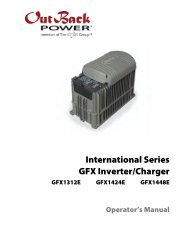
MATE At a Glance<br />
Yellow Status Indicator,<br />
AC Input LED<br />
“Hot Key”<br />
AC Input Button<br />
MAIN-------------------------<br />
1:35:04p<br />
SUM STATUS SETUP ADV<br />
Green Status Indicator,<br />
Inverter LED<br />
“Hot Key”<br />
Inverter Button<br />
LCD <strong>Display</strong><br />
Four “Soft” Keys<br />
or Buttons to scroll the<br />
menus <strong>and</strong> change values.<br />
7
MATE Specifications<br />
• Communication Protocol: proprietary <strong>OutBack</strong> multi-drop network<br />
• Interconnecting Cable: CAT 5 (8 IATIA 518B) PC non-crossover network cable<br />
• Maximum Tested Cable Length: 1000 feet (300 meters) of cable in an office/commercial<br />
building<br />
NOTE: Signal degradation can result if cable is run in conduit with AC wiring or in other<br />
electronically “noisy” environments; these can affect the maximum length the cable can run<br />
without incurring transmission errors.<br />
• PC computer interface: RS232 Opto-Isolated DB9 serial communication port<br />
NOTE: <strong>OutBack</strong> <strong>Power</strong> <strong>System</strong>s does not produce or technically support any PC computer<br />
software programs compatible with its products. The following companies sell compatible<br />
software:<br />
RightH<strong>and</strong> Engineering LLC (Winverter software)<br />
19310 226th Ave NE Woodinville, WA 98077<br />
(425) 844-1291<br />
Info@RightH<strong>and</strong>Eng.com<br />
Intellact (WattPlot software)<br />
57 Mary Street, Alton, Ontario, Canada L7K 0E3<br />
416-907-2076<br />
wattplot@intellact.ca<br />
<strong>OutBack</strong> MATE Functions<br />
Why use a MATE with your <strong>OutBack</strong> <strong>Power</strong> <strong>System</strong> FX Series Inverter/Chargers <strong>and</strong> Charge<br />
<strong>Controller</strong>s What exactly does it do<br />
A typical power system providing utility-supplied electricity requires very little from a user.<br />
Other than flipping an occasional tripped circuit breaker back on due to an overload <strong>and</strong><br />
paying a monthly bill, there is little to monitor or adjust. A renewable energy (RE) system<br />
requires more diligence <strong>and</strong> attention, including battery maintenance <strong>and</strong> setting various times<br />
<strong>and</strong> voltages for the system to act efficiently <strong>and</strong> economically.<br />
Utility-supplied power is generated, monitored, <strong>and</strong> controlled by systems you neither see nor<br />
maintain. An RE system requires some combination of inverter/chargers, batteries, charge<br />
controllers, <strong>and</strong> an RE power source, often including a generator, all of which need monitoring<br />
<strong>and</strong> adjusting for optimum performance. The <strong>OutBack</strong> MATE provides a window to your<br />
system <strong>and</strong> allows setting each <strong>OutBack</strong> component for its best <strong>and</strong> most efficient usage<br />
according to your power needs <strong>and</strong> living conditions.<br />
The MATE’s functions occur in to two general areas:<br />
1. The display of information about or the status of different system components <strong>and</strong> actions<br />
2. Enabling the user to control certain system functions, e.g., the times or the conditions<br />
under which they will occur<br />
8
What is a set point<br />
With the MATE, a user can know the system’s activity <strong>and</strong> conditions at any given time.<br />
Sometimes, after careful observations, a user might want to change the conditions or set points<br />
which cause an action to occur.<br />
A set point is a condition, measurement, or baseline a user establishes in order for<br />
something else to happen. A home thermostat offers a simple example. When predetermined<br />
temperatures <strong>and</strong> times are set for weekdays <strong>and</strong> weekends, the thermostat signals to a<br />
heating/cooling system to turn on at one time until a certain temperature is reached, maintain<br />
that temperature, <strong>and</strong> finally shut off at a later time, usually during sleep hours to conserve<br />
energy. Otherwise, the user would have to manually control the system. An outdoor light<br />
connected to a timer turns on when its set point—a certain time of the night—occurs. You can<br />
set various set points for your power system, such as when a generator turns on <strong>and</strong> shuts off,<br />
using the MATE.<br />
Among other functions, the <strong>OutBack</strong> MATE:<br />
• <strong>Display</strong>s FX Series Inverter/Charger functions <strong>and</strong> allows the user to establish the<br />
conditions—time of day or the voltage of the battery, for instance—that initiate or shut off<br />
these functions.<br />
• Shows FX AC current <strong>and</strong> AC <strong>and</strong> DC voltage-related information including the source<br />
(AC input, load, or batteries), the voltage levels of the batteries, <strong>and</strong> recharging voltages.<br />
• Instantly displays any FX or Charge <strong>Controller</strong> errors as well as the specific component<br />
affected for easier troubleshooting.<br />
• <strong>Display</strong>s Charge <strong>Controller</strong> modes, programs the FLEXmax 60 <strong>and</strong> FLEXmax 80 Charge<br />
<strong>Controller</strong>s <strong>and</strong> allows control over their AUX functions.<br />
• Using the AGS function, the MATE will start a two-wire generator at pre-set times,<br />
including different settings for weekdays <strong>and</strong> weekends, as well as exercise periods for<br />
generator maintenance.<br />
• <strong>Display</strong>s all readings of the FLEXnet DC.<br />
The MATE allows a user to view, monitor, <strong>and</strong> establish all the pertinent settings <strong>and</strong> values<br />
that occur while the system is running. From time to time, these settings <strong>and</strong> values might be<br />
adjusted as components are added or upgraded, electrical loads increase, or patterns of usage<br />
change. Making these adjustments using the MATE is similar to adjusting any number of<br />
electronic devices we all use every day, such as a clock radio whose wake-up time <strong>and</strong> stations<br />
are pre-set.<br />
Programming the start <strong>and</strong> stop times for different sources of energy (when to use gridsupplied<br />
power, stored battery power, or generator-supplied power) <strong>and</strong> determining the<br />
frequency <strong>and</strong> duration of battery recharging are highly recommended with any RE system.<br />
Many settings are based on battery voltage. Certain voltages, for example, will trigger battery<br />
recharging (a low voltage, as recommended by the battery manufacturer) while others stop<br />
recharging (a high voltage value, also recommended by the battery manufacturer). The<br />
<strong>OutBack</strong> MATE accommodates a wide range of time-based <strong>and</strong> voltage-level functions <strong>and</strong><br />
conditions for maximum control of your power system while working through the FX Series<br />
Inverter/Chargers <strong>and</strong> <strong>OutBack</strong> Charge <strong>Controller</strong>s.<br />
As you go through the manual, start with the simple functions, such as setting the system’s<br />
clock <strong>and</strong> calendar, to familiarize yourself with the <strong>OutBack</strong> MATE’s feel <strong>and</strong> capabilities.<br />
While using your system, you might change settings from time to time depending on the<br />
season of the year <strong>and</strong> the cost of grid-supplied power during peak <strong>and</strong> off-peak hours. For<br />
additional information <strong>and</strong> discussion on the <strong>OutBack</strong> MATE, please go to<br />
www.outbackpower.com <strong>and</strong> join our forum discussions.<br />
9
Manual Setup<br />
The MATE is a micro-computing device which means it is less powerful <strong>and</strong> smaller in size<br />
than a personal computer. A user will often scroll through a series of MATE screens in order<br />
to view the system status or change system conditions. This manual will show all the MATE<br />
screens <strong>and</strong> tell what they do.<br />
• Chapters 1-5: setting basic items <strong>and</strong> display options (when, how, <strong>and</strong> what you want<br />
to view) with the “soft keys,” enabling the user to get around the MATE <strong>and</strong> change its<br />
settings.<br />
• Chapters 6-7: changing the settings of MATE specific critical functions such as battery<br />
recharging (HBX), generator usage (AGS), <strong>and</strong> using grid-supplied power (Grid Use<br />
modes).<br />
• Chapter 8 <strong>and</strong> the Appendix: lists <strong>and</strong> explains all the MATE menus. Some functions are<br />
not MATE-specific functions <strong>and</strong> are placed at the end of the manual for easy searching.<br />
Values for MATE specific functions, such as FX or <strong>OutBack</strong> Charge <strong>Controller</strong> specific<br />
functions, are covered in their respective manuals.<br />
The MATE displays three kinds of screens:<br />
• Screens pertinent to the MATE’s own functions, such as its clock <strong>and</strong> display<br />
• FX function screens which deal with its inverting <strong>and</strong> charging processes<br />
• Screens showing Charge <strong>Controller</strong> modes <strong>and</strong> status<br />
• FLEXnet DC functions<br />
Although the MATE displays values <strong>and</strong> functions for the FX <strong>and</strong> <strong>OutBack</strong> Charge <strong>Controller</strong><br />
(shown as “CC” on the screens), the values reside within the components themselves.<br />
Installation<br />
The <strong>OutBack</strong> MATE:<br />
• Designed for surface mounting in an indoor location, just below the eye level of a typical<br />
user (the MATE 2 is designed for recessed installation, requiring a 13.97 cm X 10.16 cm<br />
(5 1/2” X 4”) opening to be cut in a wall <strong>and</strong> four drywall screws or other fasteners to<br />
secure it)<br />
• Readability of the display is affected by direct sunlight<br />
• Connects to other <strong>OutBack</strong> devices using st<strong>and</strong>ard non-crossover Cat5 or Cat5e cable<br />
• Has voltage less than 30 VDC <strong>and</strong> is thus considered a “limited energy circuit” normally<br />
requiring no conduit (consult your local inspector for specific installation requirements)<br />
NOTE: The MATE is shipped with (1) OBCAT 3 <strong>and</strong> (1) OBCAT 10 Cat5 cables with the<br />
correct RJ45 connectors already installed. Longer (up to 1000’) or shorter cables can be<br />
purchased (at home improvement <strong>and</strong> computer stores) pre-made or custom length cable<br />
can be made on site. Follow the cable manufactures’ instructions when choosing connectors,<br />
punch-down tools, <strong>and</strong> crimping tools. Incorrect crimping or h<strong>and</strong>ling of Cat5 cable can<br />
negatively affect the operation of the MATE. Cat5 cable is not as robust as st<strong>and</strong>ard house<br />
wiring <strong>and</strong> must be h<strong>and</strong>led carefully. Avoid kinking the cable or tearing its outer sheathing.<br />
Use plastic st<strong>and</strong>-off cable staples, J-hooks, or cable trays to support long runs of Cat5 cable.<br />
Do not splice cables. Cable runs must be protected <strong>and</strong> runs must be in approved conduit <strong>and</strong><br />
not exposed to the weather.<br />
10
To Install the MATE:<br />
• Install all other <strong>OutBack</strong> components first.<br />
• Run the CAT 5 cable from the source (HUB, FX or Charge <strong>Controller</strong>) to the MATE’s<br />
location. Connect the CAT5 cable to the source but not to the MATE just yet.<br />
• If connecting a computer to the MATE or MATE2, run a serial cable from the computer to<br />
the MATE’s location, but do not connect the cable at this time.<br />
• Unsnap the MATE’s back plate <strong>and</strong> find the four screw holes. If a MATE2 version is used,<br />
the back cover need not be removed.<br />
• The MATE <strong>and</strong> MATE2 are designed for easy wall mounting using appropriate fasteners<br />
(molly bolts, screws, etc.).<br />
• <strong>Power</strong> up every <strong>OutBack</strong> device connected directly or indirectly (through the HUB) to the<br />
MATE <strong>and</strong> then connect the CAT5 cable to the jack <strong>and</strong>, if used, the computer serial cable<br />
to the RS-232 port, on the back MATE or MATE2.<br />
• If installing the MATE, snap the MATE onto the back plate <strong>and</strong> push any excess cable back<br />
into the wall. If installing the MATE2 version, secure its four corners to the wall.<br />
MATE2 Dimensions<br />
12.7 cm (5” ) between screw holes<br />
11.43 cm (4 ½”)<br />
A C IN<br />
DC ‡ A C<br />
A C L oad<br />
Buying<br />
Battery<br />
……………….0.0 kW<br />
…. ……………………..<br />
………………………….<br />
…………….…14.4V<br />
I NV<br />
8.89 cm (3 ½” ) between screw holes<br />
15.875 cm (6 1/4”)<br />
11
12<br />
1 Basic Operation
NOTE: For a viewing of all MATE screens, please see pages 110-124 at the end of this manual.<br />
<strong>Power</strong> Up<br />
A soon as the MATE cable is plugged into a powered <strong>OutBack</strong> product, the MATE itself will<br />
power-up <strong>and</strong> display several information screens.<br />
G’day Mate<br />
First Screen<br />
(C) 2008<br />
<strong>OutBack</strong><br />
<strong>Power</strong><br />
<strong>System</strong>s<br />
Second Screen<br />
Version<br />
Code a.a.a<br />
Serial #xxxxxxxx<br />
Screen EE b.bb<br />
Third Screen<br />
• “Code” dictates the MATE’s operation <strong>and</strong><br />
features*<br />
• Serial #” matches the bar code sticker inside the<br />
MATE on its circuit board<br />
• “Screen EE” refers to the MATE’s menu system<br />
NOTE: you will need the code <strong>and</strong> serial number of the MATE if contacting <strong>OutBack</strong> <strong>Power</strong><br />
<strong>System</strong>s regarding its operation<br />
13
Searching for Devices<br />
FX Found<br />
Fourth screen (one of the following):<br />
• The MATE found an FX Series<br />
Inverter/Charger<br />
Searching for Devices<br />
CC Found<br />
• The MATE has found a Charge <strong>Controller</strong>.<br />
Searching for Devices<br />
HUB Found<br />
• The MATE has found the HUB.<br />
Searching for Devices<br />
DC Found<br />
The MATE has found the FLEXnet DC.<br />
Port Assignment<br />
1> FX 2> FX 3> CC 4> CC<br />
5> 6> 7> 8><br />
9> 10> 2M><br />
• Port Assignment screen follows the HUB Found<br />
screen<br />
• Each Port used will show its connected<br />
component.<br />
Searching for Devices<br />
No Devices Found<br />
• The MATE has not found an <strong>OutBack</strong> product.<br />
If the MATE does not find the connected device,<br />
refer to page 129, Troubleshooting<br />
14
No Device Found<br />
Would you like to Retry<br />
YES<br />
NO<br />
MAIN Screen<br />
MAIN---------------------------------<br />
12:17:04P<br />
SUM STATUS SETUP ADV<br />
The MAIN screen appears after the MATE detects<br />
the HUB (<strong>and</strong> any devices connected to it) or<br />
detects a single device if a HUB is not in use. The<br />
MAIN screen is always the same with the exception<br />
of the time display. At the bottom of the<br />
MAIN screen are the four soft key comm<strong>and</strong>s.<br />
<br />
<br />
<br />
<br />
SUMMARY shows the direction <strong>and</strong> amount<br />
of power flow in regard to inverting, charging,<br />
selling, <strong>and</strong>/or pass through. It also shows the<br />
voltage of the battery. Please see the FX <strong>and</strong> VFX<br />
Series Inverter/Charger Programming Manual for a<br />
description of these functions.<br />
The STATUS screen is the first step in viewing<br />
the status of either the <strong>OutBack</strong> Charge <strong>Controller</strong><br />
or FX Series Inverter/Charger <strong>and</strong> any of their<br />
meters <strong>and</strong> conditions.<br />
The SETUP screen leads to additional screens<br />
showing some common set points <strong>and</strong> parameters<br />
of either the MATE or an FX Series Inverter/<br />
Charger. These screens allow adjustments to such<br />
features as the MATE’s clock <strong>and</strong> background<br />
lighting or whether the power input to the FX is<br />
coming from a grid or a generator.<br />
The ADVANCED screen leads to screens for the<br />
FX Series Inverter/Charger, the <strong>OutBack</strong> Charge<br />
<strong>Controller</strong>, <strong>and</strong> the MATE itself that allow for<br />
changing each component’s advanced settings.<br />
15
Press the first two soft keys from any<br />
screen to return to the MAIN screen.<br />
MAIN---------------------------<br />
1:35:04p<br />
SUM STATUS SETUP ADV<br />
MAIN---------------------------------<br />
12:17:04P<br />
SUM STATUS SETUP ADV<br />
Navigation<br />
This section of the manual will cover how to use the buttons on the MATE to navigate the<br />
menus.<br />
MATE Buttons<br />
Yellow Status Indicator,<br />
AC Input LED<br />
AC In<br />
Hot Key<br />
MAIN---------------------------<br />
1:35:04p<br />
SUM STATUS SETUP ADV<br />
Green Status Indicator,<br />
Inverter LED<br />
INV<br />
Hot Key<br />
Soft Keys<br />
Six buttons or keys navigate the MATE <strong>and</strong> change its settings:<br />
HOT KEYS<br />
• Two FX dedicated “hot” keys are<br />
labeled AC IN <strong>and</strong> INV.<br />
• Pushing AC IN will return to the<br />
first of four AC input “hot” screens.<br />
Repeated pushing cycles through<br />
the four AC input screens.<br />
• Pushing the INV hot key will<br />
return to its “hot” screen to control<br />
the FX inverting function.<br />
SOFT KEYS<br />
• Each soft key corresponds to the word on the<br />
screen directly above it unless you are on the<br />
Summary screen.<br />
• The soft keys navigate the menus (,<br />
, , , or ).<br />
• They can change settings (, ,<br />
, to increase values <strong>and</strong> <br />
to decrease values).<br />
• The soft keys perform other functions<br />
depending on the individual menu screen.<br />
NOTE: Pressing <strong>and</strong> holding the two lower left keys at the same time will always bring up the<br />
MAIN screen. Pressing one key sooner than the other may lead to a different screen.<br />
16
How To Read a MATE Screen<br />
MATE screens will either show values that can be changed or navigate to value screens. The<br />
information on the MATE’s screen is segregated by type or task <strong>and</strong> distinguished by location<br />
on the screen <strong>and</strong> the choice of lowercase or uppercase letters. Occasionally it can be misread<br />
by a user. The following example is shown for clarification.<br />
Top line: where you are in the system <strong>and</strong> what HUB<br />
Port you’re viewing. In this example, the STATUS of<br />
the Port 1 FX METERS output voltage is displayed.<br />
HUB Port<br />
Left side: shows a<br />
condition, value label,<br />
system feature, or<br />
measurable event<br />
STATUS/FX/METERS----------P01<br />
output<br />
122 VAC<br />
voltage<br />
DOWN UP TOP PORT<br />
Right side: status,<br />
setting, or measure<br />
of value for whatever<br />
appears on the left side<br />
Bottom line: soft key comm<strong>and</strong>s allowing the<br />
user to change screens or alter a condition,<br />
feature, or event or change ports if using a HUB.<br />
Soft Key Related Abbreviations<br />
ADV - Advanced<br />
AGS – Advanced Generator Start<br />
AUX – Auxiliary Output<br />
BATT – Battery<br />
CAL – Calibration<br />
CHGR – Charger<br />
CNT - Contrast<br />
COMM – Communication<br />
DEC - Decrease<br />
DISCON – Disconnect<br />
EQ – Equalize<br />
GEN – Generator<br />
HBX – High Battery Transfer<br />
INC - Increase<br />
INV - Inverter<br />
MIN - Minutes<br />
PG1, PG2, PG3, PG4 - Page One, Page Two, etc.<br />
RSET – Reset<br />
SETP – Setup<br />
SRCH – Search<br />
STAT – Status<br />
SUM or SUMRY - Summary<br />
TMRS - Timers<br />
WARN – Warning<br />
P01—Master FX<br />
PO2, PO3, etc. - Slave FXs<br />
17
• LOCATION—the top line, STATUS/FX/METER-----P01 (the HUB’s first Port) indicates<br />
STATUS then FX then METER have been selected from the MAIN screen. Pressing the<br />
or soft keys displays the different METER screens. Pressing the <br />
soft key advances the Port number if there are other devices connected to the HUB. If no<br />
HUB is present, this will read “P00”.<br />
• LABEL—the screen’s left side shows a condition, system feature, or measurable event. If the<br />
text forms too long a statement across the screen, the words will be stacked one above the<br />
other such as “output voltage” above. When misread, it’s viewed as “output…122 vac…<br />
voltage” when in fact this screen is stating the output voltage is 122 VAC.<br />
• VALUE SETTING—the right side of this screen states the output voltage at 122 VAC. Some<br />
screens allow adjustment of this value setting when appropriate.<br />
• SOFT KEYS—the bottom line, DOWN UP TOP PORT, are the soft key comm<strong>and</strong>s which<br />
facilitate either a change of screens in the METER menu using , or<br />
soft keys or a change of HUB ports using the soft key.<br />
In other cases, a MATE navigation screen leads to a screen that can require a user’s action.<br />
The screen below, for instance, asks you to choose a category—HBX, GRIDUSE, AGS, or<br />
ADV. Once chosen, you often are given the choice to change or alter part of your system’s<br />
functioning, such as the voltage level the batteries must drop to before automatically<br />
recharging or the times the generator runs.<br />
ADV/MATE/PG1--------------------<br />
choose category:<br />
On All Screens:<br />
HBX GRIDUSE AGS PG2<br />
• Lowercase letters normally show a condition or system item that can be altered or<br />
otherwise adjusted.<br />
• Uppercase letters identify a screen’s name or indicate a step to follow to arrive at a screen<br />
with these values.<br />
Key to the Example Diagrams<br />
Soft keys<br />
Solid black indicates key can be pressed<br />
Down arrow will lead to the next screen<br />
DOWN<br />
UP<br />
Up arrow points to one or more keys that will<br />
change a value<br />
Pressing leads to the next menu<br />
Pressing leads to the previous menu<br />
18
Although the <strong>OutBack</strong> MATE menu display screens vary depending on the unit’s software<br />
version, the menu structures <strong>and</strong> navigation are the same for all versions. The MATE uses a<br />
branching menu structure to display various <strong>OutBack</strong> products’ operation modes <strong>and</strong> statuses.<br />
The menus are divided by product type <strong>and</strong> are categorized by either type of settings or the<br />
information being displayed as shown in the following example.<br />
MAIN---------------------------------<br />
12:17:04P<br />
SUM STATUS SETUP ADV<br />
STATUS SCREEN------------------<br />
choose device:<br />
FX CC DC MAIN<br />
STATUS/FX/PAGE 1----------------<br />
choose category:<br />
MODES METER BATT PG2<br />
All the screens showing the FX’s AC meters are<br />
grouped together in one menu branch allowing<br />
the user to find the required meter with a minimum<br />
of key presses.<br />
P00<br />
inv kw zer kw<br />
chg kw buys kw<br />
DOWN STATUS PORT<br />
STATUS/FX/METER–----------P00<br />
output<br />
vac<br />
voltage<br />
DOWN UP TOP PORT<br />
19
20<br />
2 MATE Setup
Set Up the MATE<br />
MAIN---------------------------------<br />
9:57:32A<br />
SUM STATUS SETUP ADV<br />
Start with the screen, which appears<br />
after the power-up screens, <strong>and</strong> press the<br />
soft key.<br />
SETUP-------------------------------<br />
choose device:<br />
FX<br />
MATE<br />
Press the soft key.<br />
SETUP/MATE/PAGE 1--------------<br />
mate code rev: 4.1.3<br />
choose category:<br />
CLOCK CNT GLOW PG2<br />
This screen displays the MATE’s code version <strong>and</strong><br />
leads to the CLOCK display, CONTRAST (CNT),<br />
<strong>and</strong> GLOW or back lighting.* Press the <br />
soft key for a second screen of SETUP choices.<br />
SETUP/MATE/PAGE2--------------<br />
choose category:<br />
PG1 SUMRY COMM PG3<br />
Press the soft key to return to the previous<br />
screen, SETUP/MATE/PAGE1. This screen<br />
leads to the SUMMARY (SUMRY) screens,<br />
which control how information is displayed. The<br />
COMMUNICATION (COMM) screens display<br />
MATE communication options.* Press the <br />
soft key to advance to the next SETUP screen.<br />
*For SUMMARY screens, please see pages 27-29.<br />
See pages 33-37 for COMMUNICATION screens.<br />
SETUP/MATE/PAGE3--------------<br />
choose category:<br />
PG2 BEEP MAIN<br />
PAGE 3 allows the user access to the BEEP<br />
function (the noise made when any key is<br />
pressed). See page 26 to activate or deactivate this<br />
function. Press the first soft key twice to return to<br />
the CLOCK function.<br />
PRESS TWICE<br />
Note: To return the MATE to its factory<br />
default settings, please see page 100.<br />
21
Setting the Clock<br />
Why you want to do it: Certain functions—such as when to use grid-supplied power (Grid-Use<br />
Mode) or generator (Advanced Generator Start Mode)—are dependent on accurate time <strong>and</strong><br />
date settings. Otherwise, the system will never work optimally.<br />
SETUP/MATE/PAGE1--------------<br />
mate code rev: 4.1.3<br />
choose category:<br />
CLOCK CNT GLOW PG2<br />
Choose from the SETUP/MATE/<br />
PAGE1 SETUP choices screen.<br />
SETUP/MATE/CLOCK--------------<br />
Tu 1/01/03<br />
12:00:00P<br />
BACK DATE TIME<br />
<strong>and</strong> adjust the MATE’s clock<br />
<strong>and</strong> calendar functions. The correct time <strong>and</strong> date<br />
are required for some MATE Control Modes to<br />
operate correctly. Pushing the soft key<br />
returns you to the previous screen.<br />
NOTE: The MATE clock does not automatically adjust for daylight savings time or leap year.<br />
Current Day<br />
Tu 9/26/07<br />
INC<br />
DAY<br />
ADJUST DAY AND THEN<br />
MONTH<br />
SET<br />
MONTH<br />
To adjust the date, press the soft key to<br />
bring up the Current Day menu.<br />
changes the day (Monday-Sunday).<br />
Press the soft key after<br />
changing the day. The next screen, which shows<br />
automatically after hitting ,<br />
adjusts the month.<br />
Current Month<br />
Mo 9/26/07<br />
INC<br />
MONTH<br />
SET<br />
DATE<br />
changes the month.<br />
Press the soft key after changing<br />
the month. The next screen adjusts the date.<br />
ADJUST MONTH AND<br />
THEN DATE<br />
22
Current Day<br />
Mo 9/26/07<br />
INC<br />
DATE<br />
SET<br />
YEAR<br />
changes the day of the month. Press<br />
the soft key after changing the date.<br />
The next screen adjusts the year<br />
ADJUST DATE AND THEN YEAR<br />
Current Year<br />
Mo 5/26/08<br />
INC DEC<br />
YEAR YEAR DONE<br />
or changes the year<br />
setting. Press the soft key after the date<br />
change is final. This returns the MATE to the<br />
SETUP/MATE/CLOCK screen.<br />
EITHER<br />
SETUP/MATE/CLOCK--------------<br />
Mo 1/01/07<br />
12:00:00P<br />
BACK DATE TIME<br />
sets the MATE’s time. Pressing the<br />
soft key leads to the Current Hour<br />
screen.<br />
Current Hour<br />
12:00:00P<br />
INC<br />
HOUR<br />
SET<br />
MIN<br />
sets the correct hour. Press the<br />
soft key when finished to return to<br />
the Current Minute screen.<br />
Current Minute<br />
12:00:00P<br />
INC DEC RESET<br />
MIN MIN SEC DONE<br />
Adjust the minutes by pressing the <br />
or soft keys as needed. Pressing the<br />
soft key begins the seconds count<br />
at zero. Pressing the soft key returns the<br />
MATE to the SETUP/MATE/CLOCK screen.<br />
23
Contrast Adjustment<br />
Why you want to do it: Everyone has different eyesight <strong>and</strong> ambient lighting varies with every<br />
location of a MATE. Like any other monitor, you may want to adjust the lighting <strong>and</strong> contrast<br />
for easier reading.<br />
PATH<br />
MAIN------------------------------------<br />
9:57:32A<br />
SUM STATUS SETUP ADV<br />
SETUP-------------------------------<br />
choose device:<br />
FX<br />
MATE<br />
SETUP/MATE/PAGE1----------------<br />
mate code rev: 4.1.3<br />
choose category:<br />
CLOCK CNT GLOW PG2<br />
SETUP/MATE/PAGE1--------------<br />
mate code rev: 4.1.3<br />
choose category:<br />
CLOCK CNT GLOW PG2<br />
Press the (CONTRAST) soft key from<br />
the SETUP/MATE/PAGE Setup choices screen.<br />
sets the desired contrast level.<br />
SETUP/MATE/CNT------------------<br />
contrast: 30%<br />
BACK INC DEC<br />
increases the contrast level <strong>and</strong> <br />
decreases the contrast level. After adjusting the<br />
contrast, press the soft key to return to<br />
the previous SETUP/MATE/PAGE 1 screen.<br />
24
Backlight Adjustment<br />
PATH<br />
MAIN------------------------------------<br />
9:57:32A<br />
SUM STATUS SETUP ADV<br />
SETUP-------------------------------<br />
choose device:<br />
FX<br />
MATE<br />
SETUP/MATE/PAGE1--------------<br />
mate code rev: 4.1.3<br />
choose category:<br />
CLOCK CNT GLOW PG2<br />
Choose from the SETUP/MATE/PAGE 1 Setup choices screen:<br />
SETUP/MATE/PAGE1--------------<br />
mate code rev: 4.1.3<br />
choose category<br />
CLOCK CNT GLOW PG2<br />
On the SETUP/MATE/GLOW screen, pressing<br />
the soft key brings up three backlight<br />
settings:<br />
• LEVEL<br />
• MODE<br />
• TIME<br />
SETUP/MATE/GLOW--------------<br />
backlight controls<br />
BACK LEVEL MODE TIME<br />
controls the backlight brightness <strong>and</strong><br />
is adjustable from 0% to 100% using <strong>and</strong><br />
soft keys.<br />
allows user to set the backlight to always<br />
off, auto-off after a time, or always on by selecting<br />
, , or , respectively.<br />
sets the auto-off time limit from 1 to 60<br />
minutes using <strong>and</strong> soft keys. This<br />
is how long the MATE waits after the last button<br />
press to turn off the backlight. Once the backlight<br />
has turned off, any button press on the MATE will<br />
turn it back on.<br />
returns to the previous screen(s) <strong>and</strong><br />
back to the SETUP/MATE/PAGE 1 screen.<br />
25
SETUP/MATE/PAGE3--------------<br />
choose category:<br />
PG2 BEEP MAIN<br />
The soft key leads to a<br />
screen controlling the MATE’s beep<br />
tone, which is made whenever a key<br />
is pressed.<br />
SETUP/MATE/BEEP--------------<br />
button beep tone ON<br />
BACK OFF ON<br />
The beep tone refers to a sound made<br />
every time a MATE soft or hot key is<br />
pushed. Press the or <br />
key for this function.<br />
26
27<br />
3 MATE Summary Screens
Summary Screen Overview<br />
The Summary screens provided by the MATE:<br />
• Summarize the current status of any FX, <strong>OutBack</strong> Charge <strong>Controller</strong> <strong>and</strong>/or FLEXnet DC<br />
connected to it.<br />
• Can be accessed from the screen by pressing the soft key <strong>and</strong> can be set<br />
to pop up like a screen saver after a delay (See Summary Screen Options on the next page<br />
for more setup information).<br />
Any MATE soft key pressed while the Summary screen is being displayed returns you to the<br />
screen that was active before the Summary screen was displayed. Pressing the two lower left<br />
soft keys at the same time opens the MAIN Menu screen.<br />
MAIN--------------------------------<br />
12:00:30P<br />
SUM STATUS SETUP ADV<br />
If the MATE has a FLEXnet DC connected to it,<br />
an initial FLEXnet DC screen will be displayed<br />
as the Summary default screen.<br />
E<br />
F<br />
Battery Discharging<br />
State of Charge 100%<br />
Pressing the second soft key brings up the next<br />
three FLEXnet DC summary screens as well as<br />
the FX <strong>and</strong> Charge <strong>Controller</strong> summary screens.<br />
DC Now 25.4V 100%<br />
In<br />
0.1A 0.000 kW<br />
Out<br />
0.4A 0.010kW<br />
Bat<br />
-0.3A 0.010kW<br />
The FLEXnet DC summary screens display<br />
the battery state of charge, including the day’s<br />
minimum, the current DC voltage, <strong>and</strong> the in<br />
<strong>and</strong> out kilowatt hours <strong>and</strong> amp hours. All the<br />
FLEXnet DC summary screens are explained in<br />
the FLEXnet DC User’s Guide which comes with<br />
that component.<br />
DC TODAY minSOC 97%<br />
In 102AH 2.70 kWH<br />
Out 93AH 2.44kWH<br />
Bat 9AH 0.26kWH<br />
DC BAT 25.4V 100%<br />
Bat<br />
-0.3A -0.010kW<br />
Net<br />
0AH 0.00kWH<br />
Days Since Full 1.1<br />
28
FX Summary Screen<br />
FX Total 12.6V 97%<br />
Inverting<br />
0.000kW<br />
AC Loads<br />
0.000kW<br />
Buying $ 0.000kW<br />
If the MATE has one or more FXs connected to<br />
it <strong>and</strong> does not have a FLEXnet DC as part of the<br />
system, an FX Summary screen will be displayed<br />
as the Summary default screen. Otherwise, it will<br />
follow the FLEXnet DC summary screens.<br />
The FX summary screen’s values summarize<br />
power flow in an FX system as well as the nontemperature<br />
compensated battery voltage.<br />
<strong>OutBack</strong> Charge <strong>Controller</strong> Summary Screen<br />
Summary Screen Options<br />
CC TOTALS 13.3V<br />
Output 0A 0.000kW<br />
Today<br />
0.0kWh<br />
0 AH<br />
The CC summary applies to all <strong>OutBack</strong> Charge<br />
<strong>Controller</strong>s. Its screen shows the voltage level of the<br />
battery (also non-temperature-compensated) <strong>and</strong><br />
the amount of power being supplied to the battery.<br />
This screen is the default Summary screen if the<br />
Charge <strong>Controller</strong> is directly connected to the HUB.<br />
The AH value applies only to the FLEXmax 80 <strong>and</strong><br />
FLEXmax 60 Charge <strong>Controller</strong>s.<br />
Why you might want them: Summary screens show the current status of one or more FXs or<br />
Charge <strong>Controller</strong>s. Given that each user <strong>and</strong> system is different, the MATE offers the choice of<br />
viewing the status of either component as well as the timing of those displays.<br />
PATH<br />
MAIN------------------------------------<br />
9:57:32A<br />
SUM STATUS SETUP ADV<br />
SETUP-------------------------------<br />
choose device:<br />
FX<br />
MATE<br />
SETUP/MATE/PAGE1------------------<br />
mate code rev: 402<br />
choose category:<br />
CLOCK CNT GLOW PG2<br />
SETUP/MATE/PAGE2-----------------<br />
choose category:<br />
PG1 SUMRY COMM PG3<br />
SETUP/MATE/PAGE2--------------<br />
choose category:<br />
PG1 SUMRY COM MAIN<br />
Press the soft key from the Setup choices screen.<br />
SETUP/MATE/SUMMARY----------<br />
summary control<br />
BACK TYPE DELAY ROLL<br />
Pressing the soft key brings up the<br />
SETUP/MATE/SUMMARY (summary control)<br />
screen options <strong>and</strong> .<br />
29
SETUP/MATE/SUMMARY---------<br />
summary control<br />
BACK TYPE DELAY ROLL<br />
To choose the SUMMARY screen you want to<br />
view automatically <strong>and</strong> also view via the MAIN<br />
menu, press the soft key on the SETUP/<br />
MATE/SUMMARY screen.<br />
SETUP/MATE/SUMMARY/TYPE---<br />
summary<br />
Roll<br />
screen type<br />
BACK INC DEC<br />
Press either or up to six<br />
times to change Summary screen<br />
Press either the <strong>and</strong> soft keys to<br />
change the summary screen<br />
Roll—switches among the FX, CC (Charge<br />
<strong>Controller</strong>), DC Only, <strong>and</strong> DC Simple summary<br />
screens automatically if an FX, Charge <strong>Controller</strong>,<br />
<strong>and</strong> FLEXnet DC are connected to the MATE<br />
through an <strong>OutBack</strong> <strong>Power</strong> <strong>System</strong>s HUB.<br />
SETUP/MATE/SUM/TYPE---------<br />
summary None<br />
screen type<br />
BACK INC DEC<br />
None—disables the SUMMARY screen from<br />
automatically opening; the SUMMARY screen can<br />
still be accessed via the soft key on the<br />
MAIN screen.<br />
SETUP/MATE/SUM/TYPE---------<br />
summary FX Only<br />
screen type<br />
BACK INC DEC<br />
FX Only—displays the FX SUMMARY screen.<br />
30
SETUP/MATE/SUM/TYPE----------<br />
summary CC Only<br />
screen type<br />
BACK INC DEC<br />
CC Only—displays the CC SUMMARY screen.<br />
Pressing the opens the DC Only summary<br />
screen.<br />
SETUP/MATE/SUM/TYPE----------<br />
summary DC Only<br />
screen type<br />
BACK INC DEC<br />
DC Only—displays the DC SUMMARY screen.<br />
Pressing the soft key opent the DC Only<br />
Simple screen.<br />
SETUP/MATE/SUM/TYPE---------<br />
summary DCSimple<br />
screen type<br />
BACK INC DEC<br />
From the DC OnlySimple screen, press the<br />
soft key to return to the summary control<br />
screen.<br />
SETUP/MATE/SUMMARY----------<br />
summary control<br />
BACK TYPE DELAY ROLL<br />
Having chosen a Summary type—None, Roll, FX Only, CC Only, DC Only or DCSimple:<br />
1. After exiting that screen, the SUMMARY screen will automatically appear whenever the<br />
MATE has been inactive for the set point (very much like a screensaver on a<br />
computer monitor).<br />
2. The chosen SUMMARY type will also be the SUMMARY manually called up by pushing<br />
the soft key on the MAIN menu.<br />
3. If the MATE is connected to a HUB with a Charge <strong>Controller</strong>, an FX, <strong>and</strong> a FLEXnet DC,<br />
it will switch among the CC, FX, DC SUMMARY, <strong>and</strong> DCSimple screens every 20 seconds<br />
when in “Roll” mode.<br />
4. If you choose “None,” the MATE continues to display the last active screen viewed; if you<br />
press the soft key on the MAIN menu when “None” is chosen, the FX SUMMARY<br />
screen appears.<br />
31
MAIN--------------------------------<br />
9:57:32A<br />
SUM STATUS SETUP ADV<br />
Pressing the soft key in the MAIN menu<br />
brings up your chosen SUMMARY screen or, if<br />
None is chosen, it will bring up the FX SUMMA-<br />
RY screen as a default. To adjust the timing of the<br />
SUMMARY screen display, see the next section.<br />
PATH<br />
MAIN-----------------------------------<br />
9:57:32A<br />
SUM STATUS SETUP ADV<br />
SETUP-------------------------------<br />
device:<br />
SETUP/MATE/PAGE1-----------------<br />
mate code rev: 402<br />
choose category:<br />
CLOCK CNT GLOW PG2<br />
SETUP/MATE/PAGE2-----------------<br />
choose category:<br />
PG1 SUMRY COMM MAIN<br />
SETUP/MATE/SUMMARY----------<br />
summary control<br />
BACK TYPE DELAY ROLL<br />
In the SETUP/MATE/SUMMARY screen, press<br />
the soft key; this will take you to<br />
the sum screen delay time screen. Pressing the<br />
soft key leads to the sum screen roll rate<br />
screen.<br />
SETUP/MATE/SUMMARY/TYPE--<br />
sum screen 19 minutes<br />
delay time<br />
BACK INC DEC<br />
SETUP/MATE/SUMMARY/TYPE--<br />
sum screen 10 seconds<br />
roll rate<br />
BACK INC DEC<br />
in SUMMARY mode shows<br />
how long it takes for a SUMMARY<br />
screen to be automatically displayed.<br />
This time can be increased or decreased<br />
by pressing the <strong>and</strong> soft<br />
keys. After the SUMMARY screen delay<br />
time is chosen, press the soft<br />
key to return you to the SETUP/MATE-<br />
SUMMARY screen.<br />
The roll rate is how often the MATE switches between<br />
the FX <strong>and</strong> CC summary screens. The rate<br />
can be adjusted with the <strong>and</strong> soft<br />
keys. Pressing the soft key returns to the<br />
SETUP/MATESUMMARY screen.<br />
32
33<br />
4 MATE Communications Options
Communications Options<br />
Why you want them: The MATE communicates comm<strong>and</strong>s to different components. It needs<br />
to be aware of any newly added or moved devices so it can recognize them. An error reading<br />
doesn’t mean the system is failing, but that the MATE is looking for a component that has been<br />
moved from one HUB Port to another or has been disconnected completely. The MATE is<br />
trying to account for the system components.<br />
PATH<br />
MAIN-----------------------------<br />
9:57:32 A<br />
SUM STATUS SETUP ADV<br />
SETUP--------------------------<br />
Choose product:<br />
FX<br />
MATE<br />
SETUP/MATE/PAGE1-----------<br />
mate code rev: 4.1.3<br />
choose category:<br />
CLOCK CNT GLOW PG2<br />
SETUP/MATE/PAGE2------------<br />
choose category:<br />
PG1 SUMRY COMM MAIN<br />
SETUP/MATE/PAGE2----------------<br />
choose category:<br />
BACK REPOLL PC DEBUG<br />
Press the soft key from the Setup choices screen for MATE<br />
communications options:<br />
• forces the MATE to “rediscover” all the <strong>OutBack</strong> devices it is connected to. This<br />
must be used any time an <strong>OutBack</strong> device is moved or added to a HUB.<br />
• will allow you to enable or disable the MATE’s RS232 communications port. This<br />
setting must be enabled if you use any third party logging or control software.<br />
• tracks communication errors involving the <strong>OutBack</strong> HUB.<br />
SETUP/MATE/PAGE2--------------<br />
choose category:<br />
PG1 SUMRY COMM MAIN<br />
From the SETUP/MATE/PAGE2 screen, press the<br />
soft key.<br />
34
SETUP/MATE/COMM--------------<br />
choose category:<br />
BACK REPOLL PC DEBUG<br />
Press the soft key after a device is<br />
added to, moved, or removed from the HUB.<br />
Searching for Devices<br />
HUB Found<br />
The MATE has found the HUB <strong>and</strong> will<br />
automatically go to the Port Assignment screen.<br />
Port Assignment<br />
1> FX 2> FX 3> CC 4> CC<br />
5> 6> 7> 8><br />
9> 10> 2M><br />
After displaying the devices connected to each<br />
Port, the MATE returns to the choose category<br />
screen on its own.<br />
NOTE: Disconnecting the MATE’s CAT5 cable <strong>and</strong> then reconnecting it also performs the<br />
re-poll task, but the cable can be inconvenient to remove from a mounted MATE.<br />
SETUP/MATE/COMM--------------<br />
choose category:<br />
BACK REPOLL PC DEBUG<br />
The next communication function deals with the<br />
MATE/personal computer interface. Press the<br />
soft key to enable or disable the MATE’s<br />
RS232 communications port.<br />
SETUP/MATE/COMM/PC----------<br />
PC communications: OFF<br />
BACK OFF ON<br />
In the PC communications screen, choose ON<br />
or OFF by pressing the respective soft key. Press<br />
the soft key to return to the choose<br />
category screen.<br />
35
SETUP/MATE/COMM--------------<br />
choose category:<br />
BACK REPOLL PC DEBUG<br />
To debug the system, press the soft<br />
key.<br />
SETUP/MATE/COMM--------------<br />
comm errors:<br />
BACK VIEW RSET<br />
On the DEBUG screen, first press the <br />
soft key to bring up a list of HUB ports with a<br />
count of communications errors for each port;<br />
allows you to reset the error counting<br />
display (see next screen).<br />
00:000 01:000 02:000<br />
03:000 04:025 05:001<br />
06:001 07:001 08:001<br />
09:001 10:001 2M:001<br />
SETUP/MATE/COMM--------------<br />
comm errors:<br />
BACK VIEW RSET<br />
This is a typical VIEW screen showing the HUB<br />
Ports <strong>and</strong> any communication errors in the<br />
system. The numbered port with more than one<br />
error will need correcting. After the errors are<br />
corrected, all the used ports will return to 000<br />
or 001 values after pushing the soft key.<br />
Press any soft key to return to the SETUP/MATE/<br />
COMM screen. To correct errors, please see “Errors<br />
<strong>and</strong> Debugging” in the section that follows. If<br />
no errors are present, pressing any soft key returns<br />
to the previous SETUP/MATE/COMM screen.<br />
Press the soft key to clear the errorcounting<br />
display. Press the soft key<br />
to return to the “choose category” screen. Press<br />
to return to the previous screen.<br />
36
Communication Errors<br />
--A COMM ERROR HAS<br />
OCCURRED<br />
VIEW<br />
DEBUG<br />
MORE<br />
INFO<br />
The A COMM (communication) ERROR<br />
HAS OCCURRED screen appears when a<br />
communication error among the components<br />
occurs.<br />
Errors <strong>and</strong> Debugging<br />
Communication errors (COMM ERR) that occur with <strong>OutBack</strong> <strong>Power</strong> <strong>System</strong>s components<br />
are often the result of loose, damaged, or unplugged cables. They can also occur if AGS (Advanced<br />
Generator Start) Mode is used <strong>and</strong> the wrong port is designated for the generator or if<br />
the system is damaged by a lightning strike. When a communication error occurs, the COMM<br />
ERR message will appear on any MATE screen in view.<br />
A sample DEBUG screen looks like this:<br />
00:000 01:000 02:000<br />
03:000 04:025 05:001<br />
06:001 07:001 08:001<br />
09:001 10:001 2M:001<br />
Explanation of Ports<br />
01:000 Port Status<br />
NOTE:<br />
• Port 00 is a MATE connected directly to<br />
an FX, no HUB is used.<br />
• Port 2M is the “2nd MATE” Port <strong>and</strong> is<br />
inoperable.<br />
Port Number<br />
• Port 00 is the MATE Port<br />
• Port 2M is inoperable.<br />
• 01—10: FX or CC Ports<br />
• 000: a device is present.<br />
• 001: no device present.<br />
• Any other status number means a<br />
device was previously present <strong>and</strong> lost<br />
contact, resulting in errors.<br />
Here’s how to read the DEBUG screen:<br />
01:000 Number of errors (zero in this case) present at this port.<br />
Port 01<br />
An unused port will show one error:<br />
09:001 Port 09 has no component; the single error is the system default.<br />
A port with a large number of errors requires action. In this example, Port 4 needs attention.<br />
04:025 Port 04 shows 25 errors.<br />
37
Advancing errors (the count is increasing on the DEBUG screen) mean the HUB is not finding<br />
a device that was previously there. In order, try the following:<br />
1. Check that the device’s DC breaker is on <strong>and</strong> operating correctly, that the device itself is on,<br />
<strong>and</strong> that the CAT5 cable connecting the device to the HUB is plugged in at both ends. Then<br />
re-poll the system (SETUP MATE PG2 COMM REPOLL, see page 34)<br />
2. Check the DEBUG screen to confirm the problem is solved.<br />
3. Swap HUB ports with another device, each using its own CAT5 cable. Re-poll the system<br />
<strong>and</strong> check for errors on each port. If the error moved, the problem is with the device or<br />
the cable between the Port <strong>and</strong> the device. If the error remains on the same Port, then the<br />
problem is with the HUB.<br />
4. Try connecting the MATE directly to the device. If the MATE recognizes the device, the<br />
problem could lie with the cable connecting the device to the HUB or with the HUB port<br />
itself. An unrecognized device could itself be damaged.<br />
38
39<br />
5 MATE Status Screens
STATUS Screen Overview<br />
Why you want them: Status screens give the user a breakdown of individual activities of the FX<br />
Series Inverter/Charger(s) <strong>and</strong> the Charge <strong>Controller</strong>(s), including AC <strong>and</strong> DC voltage <strong>and</strong> AC<br />
<strong>and</strong> FLEX net DC current meters. It is these individual readings that combine to produce the<br />
Summary screens noted earlier <strong>and</strong> allow monitoring of the system operation.<br />
MAIN---------------------------------<br />
9:57:32A<br />
SUM STATUS SETUP ADV<br />
Press on the Main menu to access the<br />
STATUS menu. STATUS contains all the meters<br />
<strong>and</strong> mode displays for <strong>OutBack</strong> products connected<br />
to the MATE.<br />
STATUS -----------------------------<br />
choose device:<br />
FX CC DC MATE<br />
The STATUS menu is divided first by product <strong>and</strong><br />
then into menu categories, such as meter, modes,<br />
<strong>and</strong> statuses.<br />
NOTE: Not all STATUS screens are applicable to all FX models. The screens differ by product<br />
type <strong>and</strong> revision. See the Menu Map at the end of the manual for locations of all of the status<br />
screens available. Consult your specific <strong>OutBack</strong> product owner manual for an explanation of<br />
all the operating modes <strong>and</strong> meters.<br />
STATUS/CC/PAGE 1--------------<br />
MODE METER SETP PG2<br />
Typical CC Status Screen<br />
STATUS/FX/PAGE 1----------------<br />
choose category<br />
MODES METER BATT PG2<br />
Typical FX Status Screen<br />
NOTE: Other than offering manual on/off control of its AUX relay, the MATE has no control<br />
over the workings of the CC Charge <strong>Controller</strong> except when the system is undergoing a global<br />
EQ charger mode. At this time, the system uses both the FX <strong>and</strong> the Charge <strong>Controller</strong>(s) to<br />
charge the batteries.<br />
40
Reading a STATUS Screen<br />
STATUS/FX/PAGE1---------------<br />
choose category<br />
MODES METER BATT PG2<br />
STATUS/FX/PAGE2---------------<br />
choose category<br />
PG1 ERROR WARN PG3<br />
STATUS/FX/PAGE3---------------<br />
choose category<br />
PG2 DISCON SELL MAIN<br />
• MODE: a functioning condition or state of operation<br />
• METER: displays inverter <strong>and</strong> charger activity, including output <strong>and</strong> input AC voltage, <strong>and</strong><br />
AC inverter, charger, <strong>and</strong> input current<br />
• BATT: displays the battery temperature, voltage <strong>and</strong> the various set points for the different<br />
recharging cycles as well as the time remaining to complete any of those cycles<br />
• PG2: pressing the soft key opens the next selection of STATUS screens<br />
• ERROR: various FX errors <strong>and</strong> their causes; an error can shut the FX down<br />
• WARN(ING): FX warning situations; warnings will not shut the FX down<br />
• PG3: Pressing the soft key opens the last STATUS screen<br />
• DISCON: lists the reasons the FX disconnects from an AC source<br />
• SELL: displays a number representing the reason the FX stops selling power to the grid; this<br />
number is used by technicians for troubleshooting grid-tied FX units<br />
The second line<br />
indicates the FX<br />
or Charge <strong>Controller</strong><br />
MODE<br />
STATUS/FX/MODE----------- P00<br />
inv control:<br />
ON<br />
CHANGE<br />
DOWN STAT MODE PORT<br />
Pressing the soft key<br />
changes the operation of the mode shown<br />
on the screen; it does not change to another<br />
mode altogether. To change modes, press the<br />
soft key.<br />
The status of<br />
“inv(erter)<br />
control” is “ON.”<br />
To choose an FX<br />
on a specific Port,<br />
press the <br />
soft key.<br />
41
FX STATUS MODE Screens<br />
STATUS/FX/PAGE1------------------<br />
choose category:<br />
MODES METER BATT<br />
PG2<br />
STATUS/FX/MODE------------P00<br />
inv control:<br />
ON<br />
CHANGE<br />
DOWN STAT MODE PORT<br />
STATUS/FX/MODE-----------P00<br />
ac in control:<br />
USE<br />
CHANGE<br />
DOWN UP MODE PORT<br />
STATUS/FX/MODE------------P00<br />
chr control:<br />
ON<br />
CHANGE<br />
DOWN UP MODE PORT<br />
STATUS/FX/MODE-------------P00<br />
aux control:<br />
AUTO<br />
CHANGE<br />
DOWN UP MODE PORT<br />
STATUS/FX/MODE-------------P00<br />
eq enabled:<br />
No<br />
CHANGE<br />
UP MODE PORT<br />
STATUS/FX/MODE------------P00<br />
inv control:<br />
ON<br />
CHANGE<br />
DOWN STAT MODE PORT<br />
Push to return to the<br />
choose category STATUS page.<br />
STATUS/FX/PAGE1--------<br />
choose category:<br />
MODES METER BATT PG2<br />
Pressing the soft key<br />
brings up the first METER screen.<br />
Push until the inv<br />
control screen appears.<br />
MODE Screens<br />
• Pressing the soft key on any<br />
MODE screen allows the user to change the operation<br />
of that individual mode, i.e., activate the function, shut<br />
it off, etc. After changing the operation (or leaving it<br />
alone), the user presses the soft key to return to<br />
the MODE screen whose operation was changed. Press<br />
the soft key to view the next mode.<br />
• inv control: shows the status of the inverter function*<br />
• AC in control: the FX accepts or drops an AC source*<br />
• chr control: shows charger activity*<br />
• aux control: controls 12 VDC <strong>and</strong> 0.7 ADC loads<br />
which can be used to run a fan, activate an alarm, signal<br />
a generator start <strong>and</strong> other low-power functions*<br />
• eq enabled: shows status of the equalize recharging<br />
cycle <strong>and</strong> allows user to start or stop the cycle*<br />
* These modes can be controlled <strong>and</strong> adjusted in greater<br />
detail in the INVERTER, CHARGER, <strong>and</strong> AUXILIARY<br />
menus <strong>and</strong> through the AC IN hot key respectively.<br />
42
FX STATUS METER Screens<br />
Charge<br />
inv 0.0kw<br />
chg 0.0kw<br />
P00<br />
zer 0.0kw<br />
buy 0.0 kw<br />
STATUS/FX/METER---------P00<br />
output<br />
117 vac<br />
voltage<br />
STATUS/FX/METER---------P00<br />
input<br />
118 vac<br />
voltage<br />
DOWN<br />
STATUS PORT<br />
DOWN UP TOP PORT<br />
DOWN UP TOP PORT<br />
STATUS/FX/METER------------P00<br />
inverter<br />
0.0 aac<br />
current<br />
DOWN UP TOP PORT<br />
STATUS/FX/METER----------P00<br />
charger<br />
0.0 aac<br />
current<br />
DOWN UP TOP PORT<br />
STATUS/FX/METER--------P00<br />
input<br />
0.0 aac<br />
current<br />
DOWN UP TOP PORT<br />
STATUS/FX/METER----------P00<br />
sell<br />
0.0 aac<br />
current<br />
STATUS/FX/METER---------P00<br />
FX firmware 61<br />
revision<br />
STATUS/FX/METER---------------<br />
end of meter menu<br />
DOWN UP TOP PORT<br />
DOWN UP TOP PORT<br />
UP<br />
TOP STATUS<br />
STATUS/FX/PAGE 1----------------<br />
choose category:<br />
MODES<br />
METER BATT PG2<br />
Push to<br />
return to the first<br />
METER screen.<br />
Push <br />
to return to the<br />
“choose category”<br />
STATUS screen.<br />
Pressing the soft key brings<br />
up the first FX BATT screen.<br />
The first METER screen shows what the<br />
inverter is doing at the time this screen<br />
is viewed. A grid-tied FX will also<br />
show any target activity. The lists below<br />
show the possible activities <strong>and</strong> target<br />
activities. An off-grid FX will only show<br />
the current activity.<br />
Activity<br />
Off<br />
Search<br />
On<br />
Charge<br />
Silent<br />
Float<br />
EQ<br />
Chr Off<br />
Support<br />
Sell<br />
Passthru<br />
Target Activity<br />
Sell<br />
RE<br />
Float<br />
Bulk EQ<br />
METER Screens<br />
The METER screens display current <strong>and</strong> voltage<br />
measure-ments <strong>and</strong> the version of FX software.<br />
• charge: the current FX mode<br />
• output voltage: available AC at the FX AC output<br />
• input voltage: available AC at the FX AC input,<br />
normally from a utility or a generator<br />
• inverter current: available current at FX AC output<br />
terminals when the inverter is ON <strong>and</strong> no AC<br />
source is connected<br />
• charger current: shows the amount of AC current<br />
used by the FX charger<br />
• input current: AC current flowing into the FX AC<br />
input<br />
• sell current: AC current being sold to the grid<br />
• FX firmware: current FX software version<br />
The METER MODE values cannot be changed in the<br />
STATUS screens.<br />
43
FX STATUS Batt(ery) Screens<br />
STATUS/FX/MODE-------------P00<br />
battery<br />
13.6 vdc<br />
actual<br />
DOWN STATUS PORT<br />
STATUS/FX/MODE-------------P00<br />
battery<br />
13.6 vdc<br />
temp compensated<br />
DOWN UP TOP PORT<br />
STATUS/FX/METER-------------P00<br />
absorb<br />
14.4 vdc<br />
setpoint<br />
DOWN UP TOP PORT<br />
STATUS/FX/BATT---------------P00<br />
absorb<br />
00.0 hrs<br />
time remaining<br />
DOWN UP TOP PORT<br />
STATUS/FX/BATT---------------P00<br />
float<br />
13.6 vdc<br />
setpoint<br />
DOWN UP TOP PORT<br />
STATUS/FX/BATT---------------P00<br />
float<br />
24.0 hrs<br />
time remaining<br />
DOWN UP TOP PORT<br />
STATUS/FX/BATT---------------P00<br />
refloat<br />
12.5 vdc<br />
setpoint<br />
DOWN UP TOP PORT<br />
STATUS/FX/BATT---------------P00<br />
equalize<br />
14.4 vdc<br />
setpoint<br />
DOWN UP TOP PORT<br />
STATUS/FX/BATT---------------P00<br />
equalize<br />
00.0 hrs<br />
time remaining<br />
DOWN UP TOP PORT<br />
STATUS/FX/BATT---------------P00<br />
batt temp. 255<br />
(not in degree C/F)<br />
DOWN UP TOP PORT<br />
STATUS/FX/BATT---------------------<br />
end of battery menu<br />
UP TOP STATUS<br />
STATUS/FX/PAGE1-------------------<br />
choose category:<br />
MODES METER BATT<br />
PG2<br />
Pressing the soft key<br />
brings up more STATUS<br />
categories.<br />
BATT(ERY) Screens<br />
• battery actual: battery voltage as measured by the FX<br />
• battery temp compensated: the Remote Temperature Sensor (RTS) must be connected to this value to be<br />
measured<br />
• absorb set point: charger set point for absorb recharging cycle<br />
• absorb time remaining: time remaining in absorb recharging cycle<br />
• float set point: battery set point for float recharging cycle<br />
• refloat set point: at this battery voltage, the charger restarts the float recharging cycle<br />
• equalize set point: charger set point for equalize recharging cycle<br />
• equalize time remaining: time remaining in equalize recharging cycle<br />
• batt temp: this value, which reflects the battery temperature, is used by the charger when an RTS is connected<br />
to the FX<br />
The BATT MODE values cannot be changed in the STATUS screens.<br />
44
FX STATUS ERROR Screens<br />
STATUS/FX/PAGE1-------------------<br />
choose category:<br />
MODES METER BATT PG2<br />
STATUS/FX/PAGE2-------------------<br />
choose category:<br />
PG1 ERROR WARN PG3<br />
STATUS/FX/ERROR-----------P00<br />
low ac output<br />
No<br />
voltage<br />
DOWN STATUS PORT<br />
STATUS/FX/ERROR----------P00<br />
stacking<br />
No<br />
error detected<br />
DOWN UP TOP PORT<br />
STATUS/FX/ERROR----------P00<br />
inverter<br />
No<br />
overtemp<br />
DOWN UP TOP PORT<br />
STATUS/FX/ERROR----------P00<br />
low battery<br />
No<br />
voltage<br />
DOWN UP TOP PORT<br />
STATUS/FX/ERROR----------P00<br />
phase loss<br />
No<br />
error<br />
DOWN UP TOP PORT<br />
STATUS/FX/ERROR----------P00<br />
high battery<br />
No<br />
voltage<br />
DOWN UP TOP PORT<br />
STATUS/FX/ERROR----------P00<br />
ac output<br />
No<br />
shorted<br />
DOWN UP TOP PORT<br />
STATUS/FX/ERROR---P00 ac output<br />
ac output<br />
backfeed<br />
DOWN UP TOP PORT<br />
STATUS/FX/ERROR------------------<br />
end of error menu<br />
UP TOP STATUS<br />
STATUS/FX/PAGE2-----------------<br />
choose category:<br />
PG1 ERROR WARN PG3<br />
Push to return to the “choose<br />
category” STATUS /FX/PAGE2<br />
Push to see<br />
the WARN(ING) Menu.<br />
ERROR Screens<br />
• low ac output voltage: inverter could not supply enough AC voltage to meet dem<strong>and</strong><br />
• stacking error detected: communication problem among stacked FXs<br />
• inverter overtemp: FX has reached its maximum allowed operating temperature<br />
• low battery voltage: battery voltage is below the LOW BATTERY CUT-OUT VOLTAGE set point (this is a<br />
common error <strong>and</strong> will light up even with low AC out or AC shorted)<br />
• phase loss error: not operational<br />
• high battery voltage: battery voltage rose above the safe high battery voltage level for 10 seconds<br />
• ac output shorted: inverter reached its maximum current <strong>and</strong> shutdown<br />
• ac output backfeed: usually indicates another AC power source was connected to the FX’s AC output<br />
ERROR screens can only display errors; they do not offer any means to correct them. These are hard faults.<br />
The LED is solid <strong>and</strong> the inverter must be turned off <strong>and</strong> then on to reset.<br />
45
FX STATUS WARN(ING) Screens<br />
STATUS/FX/PAGE2-----------------<br />
choose category:<br />
PG1 ERROR WARN PG3<br />
STATUS/FX/WARN-------------P00<br />
acin freq<br />
No<br />
too high<br />
DOWN STATUS PORT<br />
STATUS/FX/WARN-------------P00<br />
acin freq<br />
No<br />
too low<br />
DOWN UP TOP PORT<br />
STATUS/FX/WARN--------------P00<br />
acin voltage<br />
No<br />
too high<br />
DOWN UP TOP PORT<br />
STATUS/FX/WARN-------------P00<br />
acin voltage<br />
No<br />
too low<br />
DOWN UP TOP PORT<br />
STATUS/FX/WARN-------------P00<br />
acin input<br />
No<br />
current exceeds max<br />
DOWN UP TOP PORT<br />
STATUS/FX/WARN-------------P00<br />
temperature<br />
No<br />
sensor fault<br />
DOWN UP TOP PORT<br />
STATUS/FX/WARN-------------P00<br />
internal comm<br />
No<br />
error detected<br />
DOWN UP TOP PORT<br />
STATUS/FX/WARN--------------P00<br />
internal fan<br />
No<br />
failure detected<br />
DOWN UP TOP PORT<br />
STATUS/FX/WARN------------P00<br />
airtemp 190<br />
DOWN UP PORT<br />
STATUS/FX/WARN-----------P00<br />
fettemp 184<br />
DOWN UP PORT<br />
STATUS/FX/WARN-----------P00<br />
captemp 186<br />
DOWN UP PORT<br />
STATUS/FX/WARN------------------<br />
end of warnings menu<br />
STATUS/FX/PAGE2------------------<br />
choose category:<br />
STATUS/FX/PAGE2-----------------<br />
choose category:<br />
UP<br />
TOP STATUS<br />
PG1 ERROR WARN PG3<br />
PG2 DISCON SELL MAIN<br />
Push to view the DISCONNECT Menu<br />
WARN(ING) Screens<br />
• acin freq too high: AC source is above 66 Hz* (upper limit) <strong>and</strong> will be dropped if frequency gets much higher<br />
• acin freq too low: AC source is under 54 Hz** (lower limit) <strong>and</strong> will be dropped if frequency gets much lower<br />
• acin voltage too high: AC source’s voltage is over 140VAC*** (default limit) <strong>and</strong> risks loss of FX connection<br />
• acin voltage too low: AC source’s voltage is under 108VAC**** (default limit) <strong>and</strong> risks loss of FX connection<br />
• acin input current exceeds max: AC loads are drawing more current than the rating of the FX allows<br />
• temperature sensor fault: an internal FX temperature sensor is malfunctioning<br />
• internal comm error detected: there is a communication problem between the MATE <strong>and</strong> the FX<br />
• internal fan failure detected: the FX’s internal cooling fan is not operating properly<br />
• airtemp: displays a numeric value representing the air temperature around the FX*<br />
• fettemp: displays a numeric value representing the temperature of the FETs (Field Effect Transistors)*<br />
• captemp: displays a numeric value representing the temperature of the ripple capacitors<br />
(These values are used for troubleshooting purposes. The higher the numerical value, the cooler the temperature.)<br />
International FX *56 Hz **44 Hz ***270 VAC ****207<br />
46
FX DISCON(NECT) Screens<br />
STATUS/FX/DISCON-----------P00<br />
acin freq<br />
No<br />
too high<br />
DOWN STATUS PORT<br />
STATUS/FX/DISCON----------P00<br />
acin freq<br />
No<br />
too low<br />
DOWN UP TOP PORT<br />
STATUS/FX/DISCON-----------P00<br />
acin voltage<br />
No<br />
> max<br />
DOWN UP TOP PORT<br />
STATUS/FX/DISCON-----------P00<br />
acin voltage<br />
No<br />
< min<br />
DOWN UP TOP PORT<br />
STATUS/FX/DISCON----------------<br />
end of DISCON menu<br />
UP TOP STATUS<br />
STATUS/FX/PAGE2----------------<br />
choose category:<br />
PG2 DISCON SELL MAIN<br />
DISCON(NECT) Screens<br />
• acin freq too high: screen displays “Yes” if the AC source exceeds 69 Hz* <strong>and</strong> the FX disconnects from the<br />
source<br />
• acin freq too low: displays “Yes” if the FX disconnects from an AC source below 51 Hz**<br />
• acin voltage > max: the source of the AC voltage exceeds the FX maximum of 140VAC***(default value)<br />
• acin voltage < min: the source of the AC voltage falls below the FX minimum of 108VAC****(default)<br />
International FX *56 Hz **44 Hz ***270VAC ****207VAC<br />
STATUS/FX/PAGE2-----------------<br />
choose category:<br />
PG2 DISCON SELL MAIN<br />
STATUS/FX/SELL-------------<br />
stop sell 15<br />
reason<br />
STATUS<br />
PORT<br />
STATUS/FX/PAGE3-----------------<br />
choose category:<br />
PG2 DISCON SELL MAIN<br />
Press STATUS to return to the<br />
MAIN Menu.<br />
Press MAIN to return to the<br />
STATUS Menu<br />
FX SELL Screen<br />
• stop sell reason: displays a numerical value<br />
(15 in sample screen shown here) indicating<br />
a reason a grid-tied FX has stopped selling<br />
power to the utility grid; this screen is used<br />
for troubleshooting by <strong>OutBack</strong> <strong>Power</strong> <strong>System</strong><br />
technicians.<br />
Stop SELL Reasons<br />
0<br />
1 Frequency shift greater than limits<br />
2 Isl<strong>and</strong>-detected wobble<br />
3 VAC over voltage<br />
4 Phase lock error<br />
5 Charge diode battery volt fault<br />
6<br />
7 Silent comm<strong>and</strong><br />
8 Save comm<strong>and</strong><br />
9 R60 off at go fast<br />
10 R60 off at silent relay<br />
11 Current limit sell<br />
12 Current limit charge<br />
13<br />
14 Back feed<br />
15 Brute sell charge VAC over<br />
47
OUTBACK CHARGE CONTROLLER STATUS MODE Screens<br />
To view the CC STATUS screens, return to the MAIN Menu, press the soft key <strong>and</strong> then choose<br />
the CC on the STATUS choose product screen. The STATUS screens include MODE, METER, <strong>and</strong> SET (SET<br />
POINT). In STATUS Mode, these Charge <strong>Controller</strong> functions can be viewed by the MATE, but not changed.<br />
MAIN--------------------------------<br />
12:00:30P<br />
STATUS-------------------------------<br />
choose device:<br />
STATUS/CC/PAGE1------------------<br />
SUM STATUS SETUP<br />
ADV<br />
FX CC DC MAIN<br />
MODE METER SETP<br />
MAIN<br />
STATUS/CC/MODE-------------P00<br />
charger mode:<br />
Silent<br />
DOWN<br />
STATUS PORT<br />
STATUS/CC/MODE-------------P00<br />
aux relay mode:<br />
Low Batt<br />
DOWN UP TOP PORT<br />
STATUS/CC/MODE------------P00<br />
aux relay state:<br />
ON<br />
DOWN UP TOP PORT<br />
STATUS/CC/MODE-----------------<br />
end of mode menu<br />
STATUS/CC/PAGE 1-----------------<br />
UP TOP STATUS<br />
MODE METER SETP PG2 Press to view<br />
the CC METER screens.<br />
NOTE: All <strong>OutBack</strong> Charge <strong>Controller</strong> screens are displayed as CC screens on a MATE with<br />
software code revision 4.02 <strong>and</strong> higher.<br />
CHARGE CONTROLLER MODE Screens<br />
• charger mode: displays one of five charging stages (Bulk, Absorption, Float, Silent, or Equalization)<br />
• aux relay mode: displays one of eight Charge <strong>Controller</strong> AUX modes (Vent Fan, PV Trigger, ERROR<br />
OUTPUT, Night Light, Float, Diversion:Relay, Diversion:Solid St, Low Batt(ery) Disconnect, or<br />
Remote)<br />
• aux relay state: indicates if the AUX is ON or OFF<br />
48
OUTBACK CHARGE CONTROLLER STATUS METER Screens<br />
To view the CC STATUS screens, return to the MAIN Menu, press the soft key <strong>and</strong> then choose<br />
the CC on the STATUS choose product screen. The STATUS screens include MODE, METER, <strong>and</strong> SETP (SET<br />
POINT). In STATUS Mode, these Charge <strong>Controller</strong> functions can be viewed by the MATE, but not changed.<br />
mode: Silent<br />
P00<br />
in 33.2 vdc 0 adc<br />
out 13.7 vdc<br />
0 adc<br />
DOWN STATUS PORT<br />
STATUS/CC/METER-----------P00<br />
charger<br />
0 w<br />
watts<br />
DOWN UP TOP PORT<br />
STATUS/CC/METER----------P00<br />
charger<br />
.0 kwh<br />
kwhrs<br />
DOWN UP TOP PORT<br />
STATUS/CC/METER-------------P00<br />
charger<br />
+000 adc<br />
amps dc<br />
DOWN UP TOP PORT<br />
STATUS/CC/METER-----------P00<br />
charger<br />
0 ah<br />
amp hour<br />
DOWN UP TOP PORT<br />
STATUS/CC/METER-----------P00<br />
battery<br />
13.7 vdc<br />
voltage<br />
DOWN UP TOP PORT<br />
STATUS/CC/METER-----------P00<br />
panel<br />
33 vdc<br />
voltage<br />
DOWN UP TOP PORT<br />
STATUS/CC/METER-----------P00<br />
CC firmware revision<br />
001.009.003<br />
DOWN UP TOP PORT<br />
STATUS/CC/METER---------------<br />
end of meter menu<br />
UP<br />
TOP STATUS<br />
STATUS/CC-----------------<br />
MODE METER SETP MAIN<br />
Press to view the<br />
SET POINT screens<br />
NOTE: All <strong>OutBack</strong> Charge <strong>Controller</strong> screens are displayed as CC screens on the MATE.<br />
CHARGE CONTROLLER METER Screens<br />
• Mode/pv/in/bat/out: displays the charger mode, the PV array voltage, the incoming PV amps, the<br />
battery voltage, <strong>and</strong> the outgoing amps to the battery<br />
• charger watts: charger output measured in watts<br />
• charger kwhrs: kilowatt hours produced today by the Charge <strong>Controller</strong><br />
• charger amps dc: the amount of amperage the Charge <strong>Controller</strong> is sending to the battery<br />
• battery voltage: current battery voltage<br />
• panel voltage: current voltage from the PV array<br />
49
OUTBACK CHARGE CONTROLLER STATUS SETP(OINT) Screens<br />
STATUS/CC/SETPT------------P00<br />
Absorb<br />
14.4 VDC<br />
DOWN STATUS<br />
PORT<br />
STATUS/CC/SETPT------------P00<br />
Float<br />
13.6 VDC<br />
DOWN UP TOP PORT<br />
STATUS/CC/METER-----------------<br />
end of setpoint<br />
menu<br />
UP TOP STATUS<br />
Press the first two soft keys<br />
simultaneously to return to the MAIN<br />
Menu or press <strong>and</strong> then<br />
press on the STATUS screen.<br />
NOTE: All <strong>OutBack</strong> Charge <strong>Controller</strong> screens are displayed as CC screens on the MATE.<br />
CHARGE CONTROLLER SETP(OINT) Screens<br />
• Absorb: displays the voltage that initiates <strong>and</strong> maintains the Absorb cycle<br />
• Float: displays the voltage that begins the Float cycle <strong>and</strong> is maintained during this cycle<br />
50
51<br />
6 MATE Hot Keys
HOT KEYS<br />
INV Hot Key<br />
The INV “hot” key takes you to the INVERTER CONTROL screen allowing direct control of<br />
the FX’s inverter from anywhere in the menu system.<br />
MAIN-------------------------<br />
1:35:04p<br />
SUM STATUS SETUP ADV<br />
INV<br />
Hot Key<br />
The green LED indicator above the INV has three modes:<br />
• Flashing—the inverter is either in the search or power save modes<br />
• Continuously On—DC battery power is converted to AC power <strong>and</strong> the FX is supplying<br />
loads or selling to the grid<br />
• Off—the inverter is not converting DC power to AC power or when the AC input source is<br />
powering the loads<br />
PRESS ONCE:<br />
INV<br />
INVERTER CONTROL<br />
Currently: ON<br />
OFF SRCH ON OK<br />
—turns off all the FX inverters connected<br />
to the MATE<br />
—the inverter begins search mode if the<br />
AC load connected is smaller than allowed by the<br />
programming of the search function.<br />
—turns on all the FX inverters connected<br />
to the MATE.<br />
—returns to the point in the menu system<br />
where you entered the INVERTER CONTROL<br />
screen.<br />
52
AC IN Hot Key<br />
The AC IN “hot” key allows direct control of the AC input from anywhere in the menu system.<br />
INV<br />
Hot<br />
Key<br />
MAIN--------------------------<br />
1:35:04p<br />
SUM STATUS SETUP ADV<br />
The yellow LED indicator above the AC IN “hot” key has three settings:<br />
• Flashing - an AC source is available, but not connected<br />
• Continuously On - the AC source is connected <strong>and</strong> in use<br />
• Off - no AC source is present<br />
The number of AC IN key presses determines which menu is called up.<br />
AC INPUT CONTROL<br />
currently: USE<br />
DROP USE OK<br />
PRESS ONCE:<br />
• The AC INPUT CONTROL screen is<br />
called up, allowing the user to connect or<br />
disconnect the FX to an AC input source.<br />
• If a HUB is employed, AC INPUT<br />
CONTROL only affects the Master FX<br />
connected to PORT 1; the Master FX then<br />
gives the same comm<strong>and</strong> to the Slave FXs<br />
enables the FX to connect to an AC input source.<br />
disconnects the AC input source but will allow it to be reconnected if the “low<br />
battery cut-off set point” occurs or the FX is overloaded.<br />
returns to the point in the menu system before you entered the AC INPUT CONTROL<br />
menu cycle.<br />
If HBX Mode is enabled, the AC INPUT CONTROL will read:<br />
AC INPUT CONTROL<br />
currently: DROP-HBX<br />
DROP USE OK<br />
or<br />
AC INPUT CONTROL<br />
currently: USE-HBX<br />
DROP USE OK<br />
53
GEN START CONTROL<br />
currently: MAN-OFF<br />
OFF AUTO ON OK<br />
PRESS TWICE:<br />
• The GEN START CONTROL screen allows<br />
changes to the Advanced Generator Start<br />
(AGS) mode.<br />
• The AGS settings only take effect when<br />
Advanced Generator Start is enabled (See the<br />
AGS Mode section for more information).<br />
NOTE: This does not control the GenAlert<br />
function.<br />
• When an <strong>OutBack</strong> HUB is employed, the GEN START CONTROL only affects the FX<br />
programmed as the AGS PORT in the AGS setup. This is the HUB Port connected to the<br />
FX with the generator start relay.<br />
manually overrides AGS mode. Pressing brings up MAN-OFF indicating the<br />
user manually shut off the generator.<br />
allows the MATE to automatically start <strong>and</strong> stop the generator according to the<br />
settings programmed in the ADVANCED AGS menu. Pressing brings up either<br />
AUTO-OFF or AUTO-ON depending on the FX programming.<br />
manually overrides AGS mode. Pressing it brings up MAN-ON indicating the user<br />
manually turned the generator ON)<br />
Returns to the point in the menu system where you entered the GEN START<br />
CONTROL screen.<br />
NOTE: To reset an AGS error, press <strong>and</strong> then press .<br />
CHARGER CONTROL<br />
currently: AUTO<br />
OFF AUTO ON OK<br />
PRESS THREE TIMES:<br />
• The CHARGER CONTROL screen appears.<br />
• This allows the operation of the FX battery<br />
charger to be preset for an available AC source.<br />
• When an <strong>OutBack</strong> HUB is employed, the<br />
CHARGER CONTROL only affects the Master<br />
FX connected to PORT 1. The Master FX then<br />
gives the same comm<strong>and</strong> to all slave FXs.<br />
54
NOTE: The charger’s operation is independent of the inverter. With the inverter in OFF mode,<br />
the charger can be set to come on when AC is available, but have the inverter stay off when AC<br />
is disconnected.<br />
disables all charger functions in the FX.<br />
enables automatic battery charging, silent, <strong>and</strong> “re-float” when an AC input source is<br />
connected.<br />
also recharges the batteries, but eventually remains in the “float” charging stage (<strong>and</strong><br />
eliminates silent mode) until the AC input is disconnected.<br />
returns to the point in the menu system where you entered the CHARGER CONTROL<br />
screen.<br />
CHARGER MODE CONTROL<br />
global charger mode<br />
BULK EQ OK<br />
PRESS FOUR TIMES:<br />
• The CHARGER MODE CONTROL screen<br />
appears allowing the MATE to issue system<br />
(global) recharging comm<strong>and</strong>s.<br />
NOTE: Global comm<strong>and</strong>s apply to the Charge <strong>Controller</strong>s <strong>and</strong> FXs connected to a HUB.<br />
BULK CONTROL<br />
START STOP OK<br />
• Pressing brings up the BULK<br />
CONTROL screen <strong>and</strong> starts a new recharging<br />
cycle. Please see the FX <strong>and</strong> Charge <strong>Controller</strong><br />
product manuals for more information.<br />
BULK CONTROL<br />
bulk charge started<br />
OK MAIN<br />
BULK CONTROL<br />
bulk charge stopped<br />
OK MAIN<br />
The BULK CONTROL<br />
screen allows the user to<br />
manually start or stop a bulk<br />
charge cycle by pressing the<br />
or soft<br />
keys respectively.<br />
NOTE: Both Outback Charge <strong>Controller</strong> <strong>and</strong> FX products connected to the HUB will respond<br />
to global EQ <strong>and</strong> BULK charger comm<strong>and</strong>s.<br />
55
EQUALIZE CONTROL<br />
eq enabled<br />
START STOP OK<br />
Pressing on the CHARGER MODE<br />
CONTROL screen brings up the EQUALIZE<br />
CONTROL screen<br />
When has been selected, the EQ charge<br />
has stopped.<br />
EQUALIZE CONTROL<br />
eq charge stopped<br />
OK MAIN<br />
When has been selected, two<br />
informational screens are displayed. The user<br />
must push the soft key before an<br />
equalizing cycle can begin.<br />
EQ parameters must be set in<br />
ADV/FX menu. follow manuf.<br />
recommendations<br />
MORE<br />
NOTE : EQ (EQUALIZE) is not an automatic<br />
part of the FX’s charge cycle. With the AC input<br />
already connected to the FX system, an EQ charge<br />
must be manually started from this menu. The<br />
EQ cycle ends after the time it takes to charge the<br />
batteries to the EQ voltage <strong>and</strong> the EQ time limit<br />
or by manually stopping the EQ charge from this<br />
menu.<br />
NOTE: Start the generator or check that the grid<br />
is connected before starting an EQ cycle. The AC<br />
IN status LED on the FX must be solid yellow.<br />
For EQ settings ac source must be<br />
connected to start EQ cycle<br />
MORE<br />
EQ ENABLED: No<br />
are you sure you wish to start an<br />
EQ cycle<br />
YES EXIT<br />
The EQ ENABLED screen allows an equalize<br />
charging cycle or an exit. Press the soft key<br />
to enable <strong>and</strong> then press .<br />
56
To stop an equalizing process, return to the EQUALIZE CONTROL screen <strong>and</strong> press the<br />
soft key. To return to the EQUALIZE CONTROL screen:<br />
• Press the hot key four times.<br />
• Press the soft key.<br />
• Press the soft key on the EQUALIZE CONTROL screen.<br />
AC INPUT CONTROL<br />
Hot Key<br />
MAIN--------------------------<br />
1:35:04p<br />
SUM STATUS SETUP ADV<br />
CHARGER MODE CONTROL<br />
Global charger mode<br />
BULK EQ OK<br />
EQUALIZE CONTROL<br />
eq enabled Yes<br />
START STOP OK<br />
NOTE: For a global charger comm<strong>and</strong> to work, all of the <strong>OutBack</strong> products must be connected<br />
to a HUB. The CHARGER MODE CONTROL affects both FX Series Inverters/Chargers<br />
<strong>and</strong> <strong>OutBack</strong> Charge <strong>Controller</strong>s. This requires that the FX <strong>and</strong> <strong>OutBack</strong> Charge <strong>Controller</strong><br />
firmware versions support this feature (See page 129, Troubleshooting, if this comm<strong>and</strong> fails to<br />
function).<br />
57
58<br />
7 Advanced MATE Menus
MATE Control Modes<br />
The MATE, when connected to at least one FX Series Inverter/Charger, offers more sophisticated<br />
controls than basic debugging <strong>and</strong> system displays. With the MATE, you can:<br />
• Program when an FX connects to an AC source based on time, battery voltage, or time-ofday<br />
grid usage<br />
• Start a generator using Advanced Generator Start (AGS) Mode<br />
• Control auxiliary AC or DC loads such as cooling fans <strong>and</strong> relays<br />
• Sell power back to the utility grid<br />
• Set up the stacking of multiple FXs, the FLEXmax 80, <strong>and</strong> the FLEXnet DC<br />
The following chapters detail the MATE Control Modes. Please note whenever a password is<br />
called for, the system password is:<br />
The following chapters detail the MATE Control Modes.<br />
Please note whenever a password is called for, the system password is:<br />
141<br />
59
The ADVANCED Menus<br />
The MATE must be connected to an <strong>OutBack</strong> system for the Advanced features to function.<br />
MAIN-----------------------------------<br />
9:57:32 A<br />
SUM STATUS SETUP ADV<br />
To access the MATE’s Advanced Mode settings, go<br />
to the MAIN menu <strong>and</strong> push the soft key.<br />
ADV/SETTINGS/WARNING<br />
changes made could<br />
adversely effect<br />
system performance<br />
The next screen is a warning screen intended to<br />
keep those unfamiliar with an <strong>OutBack</strong> system<br />
from altering the settings. Push any key to<br />
advance to the next screen to input the password<br />
(14 MATE C1).<br />
ADV/PASSWORD---------------------<br />
enter the password<br />
132<br />
ENTER INC DEC EXIT<br />
The screen displays 132. Push the soft key<br />
until it scrolls to 14 MATE C1.<br />
ADV/PASSWORD-----------------------<br />
enter the password<br />
141<br />
ENTER INC DEC EXIT<br />
With the password 14 MATE C1 on the screen, push the<br />
soft key.<br />
60
ADV-----------------------------<br />
choose device:<br />
FX CC DC MATE<br />
In the ADV menu, push the soft key to<br />
view the Advanced MATE functions.<br />
ADV/MATE/PG1-----------------------<br />
choose category:<br />
HBX GRIDUSE AGS PG2<br />
Pressing the , , or <br />
soft keys open their specific advanced functions.<br />
Pressing the soft key opens the next<br />
MATE advanced screen.<br />
ADV/MATE/PG2-----------------<br />
choose category:<br />
PG1 DEFAULTS PG3<br />
Pressing the soft key brings up the<br />
ADV/MATE/DEFAULT screen which allows the<br />
user to re-establish all the MATE’s factory default<br />
values (see pages 96-98). Press the soft key<br />
to view the next MATE advanced screen.<br />
ADV/MATE/DEFAULT-----------<br />
reset MATE to<br />
factory default<br />
RESET NO<br />
ADV/MATE/PG3------------------------<br />
advanced charger<br />
float control<br />
PG2 CC FN-DC PG4<br />
Pressing the soft key enables charge controller<br />
float state coordination. This means when<br />
a charge controller finishes a bulk charge <strong>and</strong><br />
moves into float charge, the MATE directs any<br />
other charge controllers into a float charge as well.<br />
Pressing the soft key disables float state<br />
coordination.<br />
ADV/MATE/PG3/CC------------<br />
enable CC float<br />
coordination: Yes<br />
PG3 YES NO ADV<br />
Press the soft key to return to the previous<br />
screen.<br />
61
FLEXnet DC*<br />
ADV/MATE/PG3------------------------<br />
advanced charger<br />
float control<br />
PG2 CC FN-DC PG4<br />
Pressing the soft key brings up the<br />
FLEXnet DC charge termination screen.<br />
ADV/MATE/PG3/FN-DC---------<br />
enable FN-DC charge<br />
termination: Yes<br />
PG3 YES NO ADV<br />
Pressing the soft key enables the<br />
(FLEXnet) FN-DC charge termination. The FN-<br />
DC determines the batteries are fully charged<br />
when Charge parms met is satisfied. The MATE<br />
then comm<strong>and</strong>s all inverters <strong>and</strong> charge controllers<br />
to terminate their charge cycle.Pressing the<br />
soft key disables the FN-DC charge termination.<br />
Press the soft key to return to the<br />
previous screen.<br />
ADV/MATE/PG3------------------<br />
advanced charger<br />
float control<br />
PG2 CC FN-DC PG4<br />
Press the soft key to advance to the next<br />
ADV screen.<br />
ADV/MATE/PG4---------------<br />
FN-DC advanced grid<br />
tie authority<br />
PG3 MODE ADV MAIN<br />
The FN-DC advanced grid tie authority screen<br />
leads to screens allowing the FN-DC limited<br />
control over the GTFX (grid-tie inverter/charger).<br />
Pressing the soft key leads to those<br />
controls—disabled or Charge parms met. This is<br />
the last MATE ADV FN-DC screen.<br />
ADV/MATE/PG4/MODE----<br />
FN-DC gridtie enable<br />
disabled<br />
PG4 INC DEC ADV<br />
ADV/MATE/PG4/MODE----<br />
FN-DC gridtie enable<br />
Charge parms met<br />
PG4 INC DEC ADV<br />
*Please see the FLEXnet DC User’s Guide for<br />
all related MATE screens.<br />
In Charge parms met mode, the FN-DC detemines<br />
if the batteries are fully charged, signaling the<br />
MATE to enable the Master GTFX to sell power to<br />
the grid (the GTFX must be gridtie mode enabled<br />
first). At midnight every day, the MATE disables<br />
the GTFX’s grid-tie mode. When a renewable energy<br />
source is available later during daylight hours<br />
<strong>and</strong> the batteries are charged, sell mode returns.<br />
Pressing the or soft keys toggles<br />
the mode between Charge parms met <strong>and</strong> disabled,<br />
which shuts off FN-DC gridtie enable.<br />
62
HBX Mode<br />
What it does: HBX Mode allows control over the use of grid-supplied power based on userdetermined<br />
battery voltage <strong>and</strong> time set points. A user can maximize renewable energy use <strong>and</strong><br />
minimize the use of grid-supplied power through careful HBX usage.<br />
The <strong>OutBack</strong> default values* for HBX (24V system) are the following:<br />
• High voltage—26 volts<br />
• Low voltage—24 volts<br />
• Time for both high <strong>and</strong> low settings—one hour<br />
* Double these values for a 48V system; divide them by one half for a 12V system. These<br />
values are not temperature compensated.<br />
When the battery voltage remains at 26 volts for one hour, the FX will disconnect from the<br />
grid <strong>and</strong> the system will run on battery-supplied power. If the battery voltage falls to 24 volts<br />
for one hour, the FX connects to the grid. During this connected period, the grid-supplied AC<br />
current will power the loads <strong>and</strong> recharge the batteries unless the user manually shuts off the<br />
FX charging function off. With the charger off, the grid will only power the loads, allowing<br />
renewable energy sources to recharge the batteries. This avoids running the loads from the<br />
batteries <strong>and</strong> repeatedly charging <strong>and</strong> discharging them using more expensive utility power.<br />
To shut the charger function off:<br />
• Press the hot key three times until the CHARGER CONTROL screen appears.<br />
• Press the soft key.<br />
63
HBX Mode:<br />
• St<strong>and</strong>s for high battery transfer<br />
• Is used with grid-connected FX Series Inverter/Chargers that have utility power as their AC<br />
input<br />
• Is a mode primarily used in applications that have enough renewable energy (RE) power<br />
production to meet the needs of the loads most of the time<br />
• Allows the FX to connect to an AC source if the battery voltage has fallen below a programmable<br />
set point for a user configurable amount of time (MATE will then allow the FX to<br />
remain connected to the AC source until the battery voltage has risen above a second set<br />
point for a programmable amount of time)<br />
The MATE detects when the battery is truly low <strong>and</strong> needs charging as opposed to a sudden<br />
<strong>and</strong> momentary drop caused by a sizable dem<strong>and</strong> for power from a device such as a motor.<br />
At these times, the MATE directs the FX to use AC power until the battery is fully charged<br />
again. The user programs in the amount of time a battery can be below the low voltage <strong>and</strong><br />
the amount of time after it’s fully charged before the MATE starts issuing its comm<strong>and</strong>s. The<br />
MATE uses these times to switch back <strong>and</strong> forth between AC <strong>and</strong> battery power. Additionally,<br />
in HBX mode, the FX charging function can be shut off to allow the alternative energy source<br />
to recharge the batteries while the loads are powered by the utility grid.<br />
Press until 141, then press enter<br />
MAIN-----------------------------------<br />
8:25:04A<br />
SUM STATUS SETUP ADV<br />
ADV/SETTINGS/WARNING<br />
changes made could<br />
adversely affect<br />
system performance<br />
ADV/PASSWORD---------------<br />
enter the password<br />
132<br />
ENTER INC DEC EXIT<br />
ADV----------------------------------<br />
choose a product:<br />
FX CC DC MATE<br />
ADV/MATE/PG1--------------------<br />
choose category<br />
HBX GRIDUSE AGS PG2<br />
ADV/MATE/HBX-------------------<br />
hbx-use<br />
24.0 vdc<br />
griduse point<br />
DOWN ADV INC DEC<br />
ADV/MATE/HBX --------------------<br />
hbx-use<br />
01.0 hrs<br />
grid delay<br />
DOWN UP INC DEC<br />
ADV/MATE/HBX --------------------<br />
hbx-drop<br />
26.0 vdc<br />
grid setpoint<br />
DOWN UP INC DEC<br />
ADV/MATE/HBX -------------------<br />
hbx-drop<br />
01.0 hrs<br />
grid delay<br />
DOWN UP INC DEC<br />
ADV/MATE/HBX ---------------------<br />
ac input<br />
control<br />
DOWN UP CHANGE<br />
ADV/MATE/HBX ---------------------<br />
end of HBX menu<br />
UP TOP ADV<br />
Press <strong>and</strong> soft<br />
keys as needed to change set<br />
points<br />
64
NOTE: HBX Mode will control the Master FX Series Inverter/Charger in Port 1 of a HUB-4<br />
or HUB-10. The Master will then instruct any stacked Slaves to USE or DROP the AC input<br />
source (please see appropriate the FX programming manual for stacking instructions).<br />
Before starting HBX Mode, set or reset the established values on the four MATE set point<br />
modes shown on the following screens:<br />
• The first screen, HBX-USE GRID SET POINT appears when the HBX soft key is pressed on<br />
the previous ADV/MATE screen.<br />
• Each successive screen appears by pressing the key on the previous menu.<br />
• With these screens, the user sets the battery voltages <strong>and</strong> the amount of time these voltages<br />
must remain in order for the grid-supplied AC power to both recharge the battery <strong>and</strong> to<br />
disconnect. Since power dem<strong>and</strong> surges can briefly affect a battery’s voltage level, establishing<br />
voltage <strong>and</strong> time limits can prevent a premature or inappropriate connection to grid-supplied<br />
AC power that can occur due to a momentary change.<br />
HBX-Use Grid Set Point<br />
ADV/MATE/HBX--------------------<br />
hbx-use<br />
24.0 vdc<br />
grid setpoint<br />
DOWN ADV INC DEC<br />
This is the voltage set point that allows the FX to<br />
connect to (USE) AC power. The battery voltage<br />
must remain below the voltage listed on the<br />
screen—24.0 vdc in this case—for the amount<br />
of time programmed by the HBX-USE GRID<br />
DELAY (see next screen) before a USE comm<strong>and</strong><br />
is issued. Use the <strong>and</strong> soft keys to<br />
change the voltage set point. Press the <br />
soft key to proceed to the next screen.<br />
HBX-Use Grid Delay<br />
ADV/MATE/HBX----------------------<br />
hbx-use<br />
01.0 hrs<br />
grid delay<br />
DOWN UP INC DEC<br />
This set point—01.0 hrs in this example—is the<br />
amount of time the battery voltage must remain<br />
below the HBX-USE GRID SET POINT (above)<br />
before a USE comm<strong>and</strong> is sent. It can range from<br />
00.1 hrs to 24.0 hrs in 0.1 hour increments. Times<br />
are adjusted using the <strong>and</strong> soft<br />
keys. Press the soft key to proceed to<br />
the next screen.<br />
65
HBX-Drop Grid Set Point<br />
ADV/MATE/HBX---------------------<br />
hbx-drop<br />
26.0 vdc<br />
grid setpoint<br />
DOWN UP INC DEC<br />
This set point shows the voltage—26.0 VDC<br />
is the default for a 24V system—at which the<br />
FX will DROP its AC input source. The battery<br />
voltage must remain above this voltage for the<br />
amount of time set by HBX-DROP GRID DELAY<br />
(next screen) for a DROP to be issued. Press the<br />
soft key to proceed.<br />
HBX-Drop Grid Delay<br />
ADV/MATE/HBX---------------------<br />
hbx-drop<br />
01.0 hrs<br />
grid delay<br />
DOWN UP INC DEC<br />
This set point is the amount of time—01.0 hrs in<br />
this case—battery voltage must remain above the<br />
HBX-DROP GRID SET POINT (see previous<br />
screen) before a DROP comm<strong>and</strong> is sent. It can<br />
range from 00.1 hrs to 24.0 hrs in 0.1 hour increments.<br />
These increments are adjusted using the<br />
<strong>and</strong> soft keys. Press the <br />
soft key to proceed.<br />
AC Input Control<br />
ADV/MATE/HBX---------------------<br />
ac input<br />
USE<br />
control<br />
DOWN UP CHANGE<br />
With this screen, HBX Mode can be enabled or<br />
disabled. Pressing allows you to<br />
change the current mode in the next screen.<br />
ADV/MATE/HBX---------------------<br />
ac input<br />
USE<br />
control<br />
DROP USE HBX DONE<br />
NOTE: Before enabling HBX Mode, make sure the<br />
FX is in DROP mode by pressing the <br />
soft key. The screen will indicate DROP mode,<br />
allowing the MATE to reset the HBX values.<br />
66
ADV/MATE/HBX----------------------<br />
ac input<br />
DROP<br />
control<br />
DROP USE HBX DONE<br />
Enable HBX by pressing the soft key. The<br />
screen now indicates the MATE is running in<br />
HBX mode by displaying the current state, USE or<br />
DROP followed by HBX.<br />
ADV/MATE/HBX----------------------<br />
ac input<br />
DROP-HBX<br />
control<br />
DROP USE HBX DONE<br />
Disable HBX<br />
ADV/MATE/HBX-------------<br />
ac input<br />
DROP-HBX<br />
control<br />
DROP USE HBX DONE<br />
To disable HBX Mode, press the soft key<br />
again. After disabling HBX, the system remains in<br />
whichever state—DROP or USE—it was in while<br />
HBX Mode was active. Be sure to reset the DROP<br />
or USE to the desired state once it’s out of HBX<br />
Mode.<br />
ADV/MATE/HBX----------------------<br />
ac input<br />
DROP<br />
control<br />
DROP USE HBX DONE<br />
Pressing the soft key returns to the last<br />
HBX activated USE menu.<br />
ADV/MATE/HBX---------------------<br />
ac input<br />
DROP<br />
control<br />
DOWN UP CHANGE<br />
Press the soft key to return to the hbx-drop<br />
grid delay screen. Press the soft key to<br />
open the end of HBX menu screen.<br />
ADV/MATE/HBX---------------------<br />
end of HBX menu<br />
UP TOP ADV<br />
67
AC INPUT CONTROL<br />
Currently:USE<br />
DROP USE OK<br />
Push the hot key to view the AC status<br />
<strong>and</strong> change to USE or DROP as needed. Pressing<br />
the soft key means you accept the conditions<br />
or mode shown on the screen.<br />
MAIN-------------------<br />
1:35:04p<br />
SUM STATUS SETUP ADV<br />
NOTE: Even with HBX enabled, the user can issue manual DROP or USE comm<strong>and</strong>s using<br />
the AC INPUT CONTROL found under the ACIN hot key. Once a manual comm<strong>and</strong> is<br />
issued, the system will remain in that chosen comm<strong>and</strong> until the next HBX scheduled cycle<br />
normally occurs.<br />
Because GRID-USE Mode uses the DROP <strong>and</strong> USE comm<strong>and</strong>s, it cannot be enabled at the<br />
same time as HBX Mode. Enabling GRID-USE will automatically disable HBX Mode<br />
68
Grid-Use Mode<br />
Why you might want it: Grid-connected systems make use of utility-supplied power. The<br />
MATE’s Grid-Use Mode allows the user to pre-determine the time periods it uses the grid.<br />
NOTE: The FX’s default settings are for a generator-supported system. If your system includes a<br />
utility’s grid, set the FX to Grid by going to SETUP/FX/INPUT ac transfer control <strong>and</strong> pressing<br />
the soft key. Programming is done in the ADVANCED FX GRID <strong>and</strong> GEN menus.<br />
MAIN-----------------------------------<br />
8:25:04A<br />
SETUP--------------------------------<br />
choose a device:<br />
SETUP/FX-------------------------<br />
choose category:<br />
SUM STATUS SETUP<br />
ADV<br />
FX CC DC MATE<br />
SRCH INPUT MAIN<br />
SETUP/FX/INPUT---------------P00<br />
ac transfer<br />
Grid<br />
control<br />
DOWN GRID GEN PORT<br />
SETUP/FX/INPUT---------------P00<br />
ac1/grid<br />
limit<br />
aac<br />
DOWN INC DEC PORT<br />
SETUP/FX/INPUT---------------P00<br />
ac2/gen<br />
limit<br />
aac<br />
DOWN INC DEC PORT<br />
Will read Gen or Grid<br />
Note: These last two screens also appear in the ADVANCED menu.<br />
Grid-Use Mode allows programing the times the FX system connects to an AC input source<br />
<strong>and</strong> enables the USE mode. The time <strong>and</strong> date must be accurately programmed for Grid-Use<br />
mode to function properly.<br />
Grid-Use Mode is programmed separately for weekday <strong>and</strong> weekend connect times. Care must<br />
be taken when programming weekday <strong>and</strong> weekend times that encompass USE periods past<br />
midnight (12:00 am). The user must take into account weekday USE periods that will end on a<br />
Saturday.<br />
Example #1:<br />
Weekday Start-6:00 p.m.<br />
Weekend Start-12:00 a.m.<br />
Press <strong>and</strong> soft keys as<br />
needed to change set points<br />
Weekend Stop-12:00 a.m.<br />
The weekend USE period has been left at its default (12:00 a.m.). Any time that a Start time<br />
equals a Stop time, no action will be taken <strong>and</strong> the time period is ignored. The above settings<br />
will have the following results:<br />
• Monday—Friday evenings at 6 p.m., the MATE issues a USE comm<strong>and</strong> to the FX allowing<br />
the AC input source to be used.<br />
• Monday-Friday mornings at 6 a.m., a DROP will be issued.<br />
• On Friday evening at 6 p.m., a USE will be issued but since the Weekend Start <strong>and</strong> Stop times<br />
are equal, the weekend use time is disabled; no DROP will be issued until Monday morning<br />
at 6 a.m.<br />
69
Example #2:<br />
Weekday Start-6:00 p.m.<br />
Weekend Start-4:00 p.m.<br />
Weekday Stop-6:00 a.m.<br />
Weekend Stop-8:00 a.m.<br />
• Monday—Thursday evenings at 6:00 p.m., the MATE will issue a USE comm<strong>and</strong> to the FX<br />
allowing the AC input source to be used.<br />
• Monday—Friday at 6:00 a.m., a DROP will be issued. On Friday evening at 6:00 p.m., a USE<br />
will be issued.<br />
• The following morning is a weekend (Saturday) so a DROP comm<strong>and</strong> will be issued at 8:00<br />
a.m. During Saturday afternoon at 4:00 p.m., the FX will USE again until Sunday morning at<br />
8:00 a.m. On Sunday evening at 4:00 p.m., a USE time period will start, ending on Monday<br />
morning at 6:00 a.m.<br />
NOTE:<br />
• If the battery voltage falls below the FX’s Low Battery Cut-Off voltage, the FX will<br />
automatically connect to the AC input source regardless of the GRID-USE time of day setting.<br />
• Because GRID-USE Mode uses the DROP <strong>and</strong> USE comm<strong>and</strong>s, it cannot be enabled at the<br />
same time as HBX Mode. Enabling GRID-USE will automatically disable HBX Mode.<br />
• GRID-USE Mode only allows one Drop <strong>and</strong> Use per day. GRID-USE can be affected by the<br />
MATE not automatically adjusting its clock for Daylight Savings Time.<br />
• A START time that equals a STOP time disables a change during that period (weekdays<br />
or weekends). If disabled, the current USE or DROP comm<strong>and</strong> will continue through the<br />
disabled period. If both the weekday <strong>and</strong> weekend periods have START <strong>and</strong> STOP times that<br />
are the same, respectively, the GRID-USE Mode will be completely disabled.<br />
To enter grid use mode:<br />
Press until 141 <strong>and</strong> then press enter.<br />
MAIN<br />
9:57:32 A<br />
SUM STATUS SETUP ADV<br />
ADV/SETTINGS/WARNING<br />
changes made could<br />
adversely affect<br />
system performance<br />
ADV/PASSWORD------------------<br />
enter the password<br />
132<br />
ENTER INC DEC EXIT<br />
ADV----------------------------------<br />
choose device:<br />
FX CC DC MATE<br />
ADV/MATE-----------------------------<br />
choose category:<br />
ADV/MATE/GRIDUSE----------------<br />
griduse enable: Off<br />
ADV/MATE/GRIDUSE----------------<br />
weekday 12:00A<br />
griduse start time<br />
DOWN UP CHANGE<br />
ADV/MATE/GRIDUSE--------------<br />
weekday 12:00A<br />
griduse stop time<br />
HBX GRIDUSE AGS<br />
PG2<br />
DOWN ADV OFF ON<br />
DOWN UP CHANGE<br />
ADV/MATE/GRIDUSE---------------<br />
weekend 12:00A<br />
griduse start time<br />
DOWN ADV OFF ON<br />
ADV/MATE/GRIDUSE----------------<br />
weekend 12:00A<br />
griduse stop time<br />
DOWN UP CHANGE<br />
ADV/MATE/GRIDUSE----------------<br />
end of GRIDUSE menu<br />
UP TOP ADV<br />
70
ADV------------------------------------<br />
choose device:<br />
On the ADV menu, push the soft key.<br />
FX CC DC MATE<br />
ADV/MATE--------------------------<br />
choose category:<br />
HBX GRIDUSE AGS<br />
PG2<br />
Press the soft key on the screen.<br />
ADV/MATE/GRIDUSE---------------<br />
griduse enable: Off<br />
DOWN ADV OFF ON<br />
The first GRID-USE screen to appear is the<br />
griduse enable screen. This screen turns GRID-<br />
USE mode ON or OFF.<br />
NOTE: Set all the weekday <strong>and</strong> weekend timing first before turning the GRID-USE Mode on.<br />
The GRID-USE settings can be accessed by pressing the soft key.<br />
Weekday Grid-Use Start<br />
ADV/MATE/GRIDUSE---------------<br />
weekday 12:00A<br />
griduse start time<br />
DOWN UP CHANGE<br />
This setting is the time during the week (Monday–<br />
Friday) that a USE will be issued to the FX system,<br />
allowing it to connect to the AC input source.<br />
The time displayed is the default setting. To<br />
change the time on the adj hour screen, press the<br />
soft key<br />
71
WEEKDAY GRIDUSE START<br />
adj hour 12:00A<br />
DOWN INC DEC<br />
<strong>and</strong> set the hour to the desired<br />
time. Press to access the adj min<br />
screen.<br />
WEEKDAY GRIDUSE START<br />
adj min 12:00A<br />
INC DEC DONE<br />
<strong>and</strong> set the minutes to the desired<br />
time. Press the soft key to return to the<br />
weekday griduse start screen.<br />
ADV/MATE/GRIDUSE-----------------<br />
weekday 12:00A<br />
griduse start time<br />
DOWN UP CHANGE<br />
Press the soft key to access the ADV/<br />
MATE/GRIDUSE weekday grid-use stop screen.<br />
Weekday Grid-Use Stop<br />
ADV/MATE/GRIDUSE----------------<br />
weekday 12:00A<br />
griduse stop time<br />
DOWN UP CHANGE<br />
The WEEKDAY GRID-USE STOP setting is the<br />
time during the week (Monday-Friday) that a<br />
DROP will be issued to the FX system, forcing a<br />
disconnect from the AC input source. The time<br />
displayed is the default setting. To change the<br />
time, press the soft key <strong>and</strong> adjust<br />
the hour <strong>and</strong> minute settings on the next screens<br />
using the <strong>and</strong> soft keys. Proceed<br />
through the Adjust Hour (adj hour) <strong>and</strong> Adjust<br />
Minutes (adj min) screens in the same manner<br />
described in the weekday grid-use start section.<br />
72
Weekend Grid-Use Start<br />
ADV/MATE/GRIDUSE----------------<br />
weekend 12:00A<br />
griduse start time<br />
DOWN UP CHANGE<br />
This setting is the time during the weekend (Saturday<br />
<strong>and</strong> Sunday) that a will be issued to<br />
an FX system, allowing the FX to connect to the<br />
AC input source. The time displayed is the default<br />
setting. To change the time press the <br />
soft key <strong>and</strong> adjust the time as you would for a<br />
weekday setting. Press the soft key to<br />
view the weekend griduse stop screen.<br />
Weekend Grid-Use Stop<br />
ADV/MATE/GRIDUSE----------------<br />
weekend 12:00A<br />
griduse stop time<br />
DOWN UP CHANGE<br />
This setting is the time during the weekend (Saturday<br />
<strong>and</strong> Sunday) that a DROP will be issued<br />
to the FX system, forcing the FXs to disconnect<br />
from the AC input source. The time displayed is<br />
the default setting. To change the time press the<br />
soft key <strong>and</strong> adjust the time as you<br />
would for a weekday setting.<br />
After setting the START <strong>and</strong> STOP times, scroll<br />
back to the first GRID-USE enable screen using<br />
the soft key. Press the soft key to<br />
activate GRID-USE Mode.<br />
73
Automatic Generator Start (AGS) Mode<br />
This section applies to off-grid systems which regularly use generator-supplied power.<br />
Why you may want it: Some systems include fuel-powered generators for either back-up or<br />
regular usage. Advance Generator Start Mode sets the conditions under which a generator will<br />
automatically start <strong>and</strong> stop, eliminating inconvenient manual starts <strong>and</strong> stops. If a user isn’t at<br />
home or near the system, the generator will run anyway, in some cases keeping vital appliances<br />
<strong>and</strong> motors running.<br />
Advanced Generator Start (AGS) Mode utilizes the auxiliary (AUX) output found on each FX<br />
<strong>and</strong> is compatible with any two- wire start generator. AGS offers a variety of conditions that<br />
will start a generator by energizing the FX AUX output or the FLEXnet DC relay output.<br />
AGS starts the generator anytime one or more of the Gen Start conditions are true <strong>and</strong> will<br />
stop the generator only when all of the conditions are false except during a programmed Quiet<br />
Time (normally at night when a noisy generator would be disturbing).<br />
NOTE: Low Battery Cut Out overrides Quiet Time.<br />
GenAlert is another way to automatically start a generator, but it does not offer the range of<br />
programming options as AGS. AGS is a function of the MATE while GenAlert is a function of<br />
the FX, which is programmed using the MATE. Information on the GenAlert function can be<br />
found in the FX programming <strong>and</strong> operations manual.<br />
NOTE: Choose either AGS or GenAlert to automatically start your generator. Enabling AGS<br />
overrides all AUX control functions of that particular inverter.<br />
AGS can start a generator under the following variety of settings:<br />
• Voltage Start<br />
• Load Start<br />
• Must Run<br />
• State of Charge % Start (FLEXnet DC)<br />
• Exercise<br />
SAFETY WARNING: AGS can cause severe damage if the generator <strong>and</strong> battery bank are<br />
not properly maintained.<br />
74
AGS Setup<br />
To enter the AGS setup, go to the screen:<br />
MAIN-----------------------------------<br />
9:57:32 A<br />
SUM STATUS SETUP ADV<br />
ADV/SETTINGS/WARNING<br />
changes made could<br />
adversely affect<br />
system performance<br />
Press until 141 <strong>and</strong><br />
then press <br />
ADV/PASSWORD--------------<br />
enter the password<br />
132<br />
ENTER INC DEC EXIT<br />
ADV----------------------------------<br />
choose device:<br />
FX CC DC MATE<br />
ADV/MATE/PG1-----------------------<br />
choose category:<br />
Press the soft key.<br />
HBX GRIDUSE AGS<br />
PG2<br />
ADV/MATE/AGS------------------------<br />
choose category:<br />
QUIET VOLT<br />
SETUP TIME START PG2<br />
Press the soft key.<br />
75
The AGS Setup menu contains the following general settings that define the AGS routines.<br />
AGS Port<br />
The MATE uses the AUX output of an FX or FLEXnet DC relay to control the generator. The<br />
MATE is connected to this FX either directly or through a HUB.<br />
If a HUB is used:<br />
• Use the <strong>and</strong> soft keys to set the AGS Port value to the HUB FX or FLEXnet<br />
DC Port controlling the generator.<br />
If no HUB is used <strong>and</strong> the MATE is directly plugged into an FX, then the AGS Port needs to be<br />
set to 0 (zero).<br />
Example:<br />
ADV/MATE/AGS/SETUP-------------<br />
ags port: 0<br />
DOWN AGS INC DEC<br />
ADV/MATE/AGS/SETUP---------------<br />
ags port: 3<br />
DOWN AGS INC DEC<br />
A MATE is connected to a HUB-10 that has four<br />
FXs <strong>and</strong> three Charge <strong>Controller</strong>s connected to it.<br />
The FXs are plugged into Ports 1 – 4, as labeled on<br />
the HUB, <strong>and</strong> the Charge <strong>Controller</strong>s are plugged<br />
into Ports 5 – 7. Any FX can have its AUX output<br />
wired to a relay whose contacts are wired to the<br />
starting circuitry of the generator. The AGS Port<br />
must be set to the port of the chosen FX.<br />
After setting the AGS Port, press the <br />
soft key. The next screen allows you to enable the<br />
AGS Mode.<br />
76
AGS Enabled<br />
ADV/MATE/AGS/SETUP------------<br />
AGS enabled:<br />
NO<br />
DOWN UP NO YES<br />
This is the overall control for the AGS Mode. If<br />
AGS is not enabled, none of the AGS settings<br />
or controls will work. Enable the AGS first by<br />
pressing the
DC Genset<br />
ADV/MATE/AGS/SETUP<br />
dc genset<br />
NO<br />
DOWN UP NO YES<br />
In this screen, YES means a DC generator is<br />
present <strong>and</strong> the AGS routine, which normally<br />
stops the generator upon the FX going to Float or<br />
Silent, will instead stop the generator when the<br />
vdc genstop setting is reached.<br />
NOTE: If you have a generator that produces AC<br />
voltage, maintain the NO status shown on this<br />
screen.<br />
VDC Genstop<br />
ADV/MATE/AGS/SETUP-----<br />
vdc genstop: 38.0 vdc<br />
DOWN UP INC DEC<br />
Press the soft key to go to the vdc<br />
genstop screen.<br />
This voltage setting will terminate a Voltage Start<br />
comm<strong>and</strong> when the battery voltage remains above<br />
it for 15 minutes regardless of the DC Genset<br />
setting. The setting can be adjusted using the<br />
<strong>and</strong> soft keys. Press the <br />
soft key to view the AGS fault time screen.<br />
NOTE: The vdc genstop will turn off a generator<br />
even if the dc genset on the previous screen says<br />
.<br />
ADV/MATE/AGS/SETUP-----<br />
AGS fault time 17<br />
minutes<br />
DOWN UP INC DEC<br />
AGS Fault Time is the period the generator is<br />
given to connect to the FX system after the AUX<br />
output has been activated. If the generator fails<br />
to connect <strong>and</strong> provide AC current, the MATE<br />
displays an AGS error. The user can set this time<br />
anywhere from 5-30 minutes by pressing the<br />
<strong>and</strong> soft keys. Press the <br />
soft key to reach the cool down time screen.<br />
78
ADV/MATE/AGS/SETUP-----<br />
cool down time 0<br />
minutes<br />
DOWN UP INC DEC<br />
After the FX charging has been disabled, the cool<br />
down time screen allows the user to adjust the<br />
number of minutes the generator will cool down<br />
before being shut off. This time should follow<br />
the manufacturer’s recommendations. Press the<br />
key to view the warm up time screen<br />
ADV/MATE/AGS/SETUP-----<br />
warm up time 0<br />
minutes<br />
DOWN UP INC DEC<br />
The warm up time screen allow the user to<br />
adjust the number of minutes the generator<br />
will warm up before the FX charging begins.<br />
This time should follow the manufacturer’s<br />
recommendations. Press the key to<br />
view the End of AGS SETUP time screen<br />
NOTE: Cool down <strong>and</strong> warm up times are not<br />
used when DC generator (dc genset) is selected.<br />
NOTE: Cool down <strong>and</strong> warm up times are not<br />
used when DC generator (dc genset) is selected.<br />
End of AGS SETUP<br />
menu<br />
UP TOP AGS<br />
In the End of the AGS SETUP screen Press<br />
the soft key for more AGS<br />
programming.<br />
79
Advanced Generator Start (AGS) Test<br />
Generators are an integral part of many renewable energy systems. Setting a generator’s start<br />
<strong>and</strong> stop times <strong>and</strong> voltage set points can be confusing. The following test helps assure your<br />
generator is properly functioning <strong>and</strong> the programming is accurate (AGS must be set up first in<br />
order to perform this test).<br />
Before any further programming, confirm that the generator is working properly by manually<br />
turning it on <strong>and</strong> then shutting it off.<br />
GEN START CONTROL<br />
currently: AUTO<br />
OFF AUTO ON OK<br />
PRESS TWICE:<br />
• Brings up the GEN START CONTROL screen.<br />
• Press the soft key <strong>and</strong> wait for the<br />
generator to go on.<br />
• Press the soft key to shut the generator<br />
off.<br />
• Press the soft key to put the generator<br />
in AUTO mode<br />
• Press the soft key to return to the ADV/<br />
MATE/AGS screen.<br />
The AGS test confirms the AGS function works <strong>and</strong> the generator has been enabled during<br />
the AGS programming. Sometimes the GEN ALERT set points <strong>and</strong> properties get confused<br />
with AGS <strong>and</strong> this test confirms the correct set points are used. GEN ALERT set points<br />
should not be used as AGS set points. These are two separate methods for starting a generator<br />
automatically.<br />
Quiet Time<br />
Why do you might want it: If Quiet Time Mode is set, the MATE will not allow most AGS<br />
settings to start the generator during the Quiet Time window. This is usually set up during<br />
night time when a running generator would be an annoyance. Quiet Times can be set<br />
individually for weekday <strong>and</strong> weekend, <strong>and</strong> consist of a Quiet Time Start <strong>and</strong> a Quiet Time Stop.<br />
NOTE: The 2-minute Voltage set point (see page 86) will override Quiet Time settings. This is<br />
necessary to prevent the battery from falling below an unacceptable voltage.<br />
As with GRID-USE settings, if you set the START <strong>and</strong> STOP modes for the same time (for<br />
example, 12:00 a.m.), each will be ignored. To program Quiet Time Mode, go to the advanced<br />
MATE menu.<br />
80
PRESS UNTIL 141 AND THEN PRESS ENTER<br />
MAIN-----------------------------------<br />
9:57:32A<br />
SUM STATUS SETUP ADV<br />
ADV/SETTINGS/WARNING<br />
changes made could<br />
adversely affect<br />
system performance<br />
ADV/PASSWORD---------------------<br />
enter the password<br />
131<br />
ENTER INC DEC EXIT<br />
ADV----------------------------------<br />
choose device:<br />
FX CC DC MATE<br />
ADV/MATE/PG1---------------------<br />
choose category<br />
HBX GRIDUSE AGS PG2<br />
Go to the ADV/MATE screen <strong>and</strong> press the<br />
soft key.<br />
ADV/MATE/AGS----------------------<br />
choose category:<br />
QUIET VOLT<br />
SETUP TIME START PG2<br />
Next, press the soft key.<br />
Weekday Start<br />
ADV/MATE/AGS/QT---------------<br />
weekday 12:00A<br />
quiet time start<br />
DOWN AGS CHANGE<br />
weekday quiet time start is the beginning of the<br />
Monday-Friday quiet time period. Most AGS<br />
start conditions will be stopped during this<br />
time. adjusts the hour <strong>and</strong> minutes<br />
settings.<br />
81
WEEKDAY QT START<br />
adj hour 12:00A<br />
DOWN INC DEC<br />
<strong>and</strong> adjust the weekday start<br />
hours. When finished, press the soft<br />
key.<br />
WEEKDAY QT START<br />
adj min 12:00A<br />
INC DEC DONE<br />
<strong>and</strong> adjust the weekday start minutes.<br />
When finished, press the soft key.<br />
This will return you to the ADV/MATE/AGS/QT<br />
weekday quiet time start menu.<br />
ADV/MATE/AGS/QT------------------<br />
weekday: 12:00A<br />
quiet time start<br />
DOWN AGS CHANGE<br />
Press the soft key to go to the weekday<br />
quiet time stop screen.<br />
Weekday Stop<br />
ADV/MATE/AGS/QT------------------<br />
weekday 12:00A<br />
quiet time stop<br />
DOWN AGS CHANGE<br />
weekday quiet time stop is the end of the quiet<br />
time period for Monday-Friday. To change the<br />
time, press the soft key <strong>and</strong> adjust<br />
the hour <strong>and</strong> minute settings on the next screens<br />
using the <strong>and</strong> soft keys. Proceed<br />
through the adj hour <strong>and</strong> adj min screens in the<br />
same manner described in the Weekday Start<br />
section. Press the soft key on the final<br />
ADV/MATE/AGS/QT weekday quiet time stop<br />
screen to open the weekend screens.<br />
82
Weekend Start<br />
ADV/MATE/AGS/QT------------------<br />
weekend: 12:00A<br />
quiet time start<br />
DOWN UP CHANGE<br />
weekend quiet time start is the beginning of the<br />
quiet time period for Saturday <strong>and</strong> Sunday. Most<br />
AGS start conditions will be stopped during this<br />
time. Press the soft key to adjust the<br />
hour <strong>and</strong> minutes settings.<br />
WEEKEND QT START---------------<br />
adj hour 12:00A<br />
DOWN INC DEC<br />
<strong>and</strong> adjust the hourly setting for<br />
the WEEKEND QT START. Press the <br />
soft key when finished.<br />
WEEKEND QT START----------------<br />
adj min 12:00A<br />
INC DEC DONE<br />
<strong>and</strong> adjust the minutes setting for<br />
the WEEKEND QT START. Press the <br />
soft key when finished.<br />
ADV/MATE/AGS/QT------------------<br />
weekend: 12:00A<br />
quiet time start<br />
DOWN UP CHANGE<br />
If you are satisfied with the weekend quiet time<br />
start settings, press the soft key <strong>and</strong> go<br />
to the weekend stop screen.<br />
83
Weekend Stop<br />
ADV/MATE/AGS/QT------------------<br />
weekend 12:00A<br />
quiet time stop<br />
DOWN UP CHANGE<br />
weekend quiet time stop is the end of the quiet<br />
time period for Saturday & Sunday. <br />
adjusts the hour <strong>and</strong> minutes settings.<br />
WEEKEND QT STOP-----------------<br />
adj hour 12:00A<br />
DOWN INC DEC<br />
<strong>and</strong> adjust the hourly setting for<br />
the WEEKEND QT STOP. Press the <br />
soft key when finished.<br />
WEEKEND QT STOP----------------<br />
adj min 12:00A<br />
INC DEC DONE<br />
<strong>and</strong> adjust the minute setting for<br />
the WEEKEND QT STOP. Press the <br />
soft key when finished.<br />
ADV/MATE/AGS/QT---------------<br />
weekend 12:00A<br />
quiet time stop<br />
DOWN UP CHANGE<br />
If you are satisfied with the weekend quiet time<br />
stop settings, press the soft key <strong>and</strong> go<br />
to the end of the quiet time menu.<br />
ADV/MATE/QUIET TIME-----------<br />
end of QUIET TIME<br />
menu<br />
UP TOP AGS<br />
Press the soft key to return to ADV/<br />
MATE/AGS screen.<br />
84
Voltage Start<br />
There are three voltage start set points in AGS Mode that the user can adjust. After a generator<br />
is started due to a Voltage Start setting, it will be stopped when the FX completes the absorb<br />
charge or based on the VDC Genstop setting in the AGS Setup menu previously explained.<br />
NOTE: If the DC Genset is set to YES, the generator will only stop after the battery voltage has<br />
reached the VDC Genstop voltage for 15 minutes.<br />
ADV/MATE/AGS------------------------<br />
Choose category:<br />
QUIET VOLT<br />
SETUP TIME START PG2<br />
To get to the Voltage Start screen, press the<br />
soft key on the ADV/MATE/<br />
AGS screen.<br />
24-Hour Voltage Set Point<br />
ADV/MATE/AGS/VSTART-----------<br />
volt start<br />
24.4 vdc<br />
24 hr setting<br />
DOWN AGS INC DEC<br />
If the battery voltage falls below this set point, a 24<br />
hour timer starts counting down. Upon reaching<br />
zero, a start comm<strong>and</strong> is sent to the generator<br />
unless it is currently Quiet Time. To change the<br />
default settings, use the <strong>and</strong> soft<br />
keys. When finished, press the soft key<br />
to go to the volt start 2 hr setting screen.<br />
2-Hour Voltage Set Point<br />
ADV/MATE/AGS/VSTART------------<br />
volt start<br />
23.6 vdc<br />
2 hr setting<br />
DOWN UP INC DEC<br />
If the battery voltage falls below this set point, a 2<br />
hour timer starts to count down. After reaching<br />
zero, a start comm<strong>and</strong> is sent to the generator<br />
unless it is currently Quiet Time. To change the<br />
default settings, use the <strong>and</strong> soft<br />
keys. When finished, press the soft key<br />
to go to the volt start 2 min setting screen.<br />
85
2-Minute Voltage Set Point<br />
ADV/MATE/AGS/VSTART-----------<br />
volt start<br />
22.0 vdc<br />
2 min setting<br />
DOWN UP INC DEC<br />
If the battery voltage falls below this set point, a<br />
2-minute timer starts to count down. Upon reaching<br />
zero, a start comm<strong>and</strong> is sent to the generator<br />
even if it is currently Quiet Time. Use the <br />
<strong>and</strong> soft keys to change the default settings.<br />
When finished, press the soft key<br />
to go to the end of VOLTAGE START menu.<br />
ADV/MATE/AGS/VSTART-----------<br />
end of VOLTAGE START menu<br />
Press the soft key to return to ADV/<br />
MATE/AGS<br />
UP TOP AGS<br />
Load Start<br />
Why you might want it: Instead of the generator starting only at preset times or according to<br />
battery voltage conditions, Load Start allows it to start because the dem<strong>and</strong> for electricity is<br />
high. This should prevent the batteries from being depleted. As soon as the dem<strong>and</strong> decreases<br />
<strong>and</strong> the batteries can adequately fulfill it, the generator will shut off.<br />
Load Start will start a generator whenever the total system AC Load exceeds the set point for<br />
the programmed amount of time. The generator will then be stopped when the AC load has<br />
dropped below a Load Stop set point for a programmed amount of time.<br />
When the generator is running because of Load Start, the FX system will charge the batteries.<br />
This charge might not be completed if the generator is disconnected because of Load Stop.<br />
NOTE: Large instantaneous loads can still overcurrent the inverter prior to the generator<br />
starting <strong>and</strong> getting in sync with the inverter.<br />
86
To open the Load Start screen:<br />
ADV/MATE/AGS-----------------------<br />
choose category<br />
QUIET VOLT<br />
SETUP TIME START PG2<br />
Go to the ADV/MATE/AGS screen <strong>and</strong> press the<br />
soft key.<br />
ADV/MATE/AGS/PG2----------------<br />
choose category<br />
LOAD MUST<br />
PG1 START RUN PG3<br />
At the ADV/MATE/AGS/PG2 screen, press the<br />
soft key.<br />
Load Start KW<br />
ADV/MATE/AGS/LS------------------<br />
load start<br />
0 kw<br />
DOWN AGS INC DEC<br />
In the load start kw screen, an AGS start comm<strong>and</strong><br />
will be issued when the total AC load of all the FXs<br />
connected to the MATE exceeds this setting for the<br />
load start delay (next screen) time. A zero value<br />
disables any load start function. <strong>and</strong> <br />
adjusts this setting between 1 – 50kW. After the<br />
value has been set, press the soft key to<br />
get to the load start delay screen.<br />
Load Start Delay<br />
ADV/MATE/AGS/LS------------------<br />
load start<br />
delay<br />
1 min<br />
DOWN UP INC DEC<br />
This setting is the delay time that the total system AC<br />
load must remain above the load start kw setting (see<br />
previous screen), before the generator is started. It is<br />
adjustable from 1 to 240 minutes using the <br />
<strong>and</strong> soft keys. After making any adjustments<br />
to the delay time, press the soft key to go<br />
to the load stop kw screen.<br />
87
Load Stop KW<br />
Load Stop Delay<br />
ADV/MATE/AGS/LS-----------------<br />
load stop<br />
0 kw<br />
DOWN UP INC DEC<br />
ADV/MATE/AGS/LS----------------<br />
load stop<br />
1 min<br />
delay<br />
DOWN UP INC DEC<br />
An AGS stop comm<strong>and</strong> will be issued when the<br />
total AC load of all the FXs connected to the<br />
MATE falls below this setting for the amount of<br />
time set with load stop delay (next screen) as long<br />
as the generator was started due to Load Start.<br />
This setting excludes any FX charger current<br />
for its AC load calculation. The setting can be<br />
changed using the <strong>and</strong> soft keys.<br />
Pressing the soft key leads to the load<br />
stop delay screen.<br />
This setting is the delay time the total system AC<br />
load must remain below the Load Stop kw before<br />
the generator is stopped. It is adjustable from 1 to<br />
240 minutes using the <strong>and</strong> keys.<br />
Pressing the soft key leads to the end of<br />
the VOLTAGE START menu screen.<br />
ADV/MATE/AGS/LS---------------<br />
end of the LOAD<br />
START menu<br />
UP TOP AGS<br />
Pressing the soft key returns the ADV/<br />
MATE/AGS/PG2 screen<br />
88
Must Run<br />
Why you might want it: In time, a user can determine patterns in energy usage <strong>and</strong> dem<strong>and</strong>s<br />
on batteries. Must Run times the generator usage to the heaviest user dem<strong>and</strong>s during a day,<br />
thus avoiding depleting the batteries or requiring a long recharging period. This might happen<br />
in the mornings or early evenings when a family’s power dem<strong>and</strong> is higher.<br />
Must Run Time is a daily time period when the MATE comm<strong>and</strong>s the generator to run. Must<br />
Run Times can be set individually for weekdays <strong>and</strong> weekends <strong>and</strong> consist of a must run start<br />
time <strong>and</strong> a must Run stop time. Setting must run start <strong>and</strong> stop times to the same time disables<br />
the Must Run function. To go to the Must Run screens, press the soft key on the<br />
ADV/MATE/AGS/P2 screen.<br />
ADV/MATE/AGS/PG2---------------<br />
choose category<br />
LOAD MUST<br />
PG1 START RUN PG3<br />
From the ADV/MATE/AGS/PG2 screen, press<br />
the soft key <strong>and</strong> open the ADV/<br />
MATE/AGS/MR weekday must run start time<br />
screen.<br />
Weekday Start<br />
ADV/MATE/AGS/MR----------------<br />
weekday 12:00A<br />
must run start time<br />
DOWN AGS CHANGE<br />
weekday must run start time is the beginning of<br />
the time period Monday-Friday that the generator<br />
will be forced to run. Press to adjust<br />
the hour <strong>and</strong> minutes settings using the <br />
<strong>and</strong> soft keys.<br />
WEEKDAY MR START<br />
adj hour 12:00A<br />
DOWN INC DEC<br />
Adjust the weekday must run start time minutes<br />
with the <strong>and</strong> soft keys. Press the<br />
soft key to view the adj min screen.<br />
WEEKDAY MR START<br />
adj min 12:00A<br />
INC DEC DONE<br />
After the minutes have been set, press the<br />
soft key to return to the ADV/MATE/<br />
AGS/MR weekday must run start time screen.<br />
89
ADV/MATE/AGS/MR----------------<br />
weekday: 12:00A<br />
must run start time<br />
DOWN AGS CHANGE<br />
weekday must run stop time is the end of the Must<br />
Run time period for Monday-Friday. Press the<br />
soft key to go to the weekday must run<br />
stop screen.<br />
Weekday Stop<br />
ADV/MATE/AGS/MR------------------<br />
weekday: 12:00A<br />
must run stop time<br />
To adjust the start time hour <strong>and</strong> minute settings,<br />
press the soft key.<br />
DOWN UP CHANGE<br />
WEEKDAY MR STOP<br />
adj hour 12:00A<br />
DOWN INC DEC<br />
Adjust the hours using the <strong>and</strong> <br />
soft keys. When finished, press the soft<br />
key to adjust the minutes.<br />
WEEKDAY MR STOP<br />
adj min 12:00A<br />
INC DEC DONE<br />
Adjust the minutes using the <strong>and</strong> <br />
soft keys. When finished, press the soft<br />
key to return to the ADV/MATE/AGS/MR weekday<br />
must run stop time screen.<br />
90
Weekend Start<br />
ADV/MATE/AGS/MR----------------<br />
weekday 12:00A<br />
must run stop time<br />
DOWN UP CHANGE<br />
Press the soft key in the ADV/MATE/<br />
AGS/MR screen to adjust the weekend must run<br />
start time.<br />
ADV/MATE/AGS/MR-----------------<br />
weekend 12:00A<br />
must run start time<br />
DOWN UP CHANGE<br />
weekend must run start time is the beginning<br />
of the time period, Saturday <strong>and</strong> Sunday, that<br />
the generator will be forced to run. To adjust<br />
the weekend must run start time, press the<br />
soft key.<br />
WEEKEND MR START<br />
adj hour 12:00A<br />
DOWN INC DEC<br />
Adjust the weekend must run start time hours<br />
using the <strong>and</strong> soft keys. Press the<br />
soft key when finished.<br />
WEEKEND MR START<br />
adj min 12:00A<br />
INC DEC DONE<br />
Adjust the weekend must run start minutes using<br />
the <strong>and</strong> soft keys. Press the<br />
soft key to return to the ADV/MATE/<br />
AGS/MR weekend must run stop time screen when<br />
finished.<br />
91
ADV/MATE/AGS/MR-----------------<br />
weekend 12:00A<br />
must run start time<br />
Press the soft key to go to the ADV/<br />
MATE/AGS/MR weekend must run stop screen.<br />
DOWN UP CHANGE<br />
Weekend Stop<br />
ADV/MATE/AGS/MR-----------------<br />
weekend 12:00A<br />
must run stop time<br />
DOWN UP CHANGE<br />
weekend must run stop time is the end of the must<br />
run time period for Saturday <strong>and</strong> Sunday. Press<br />
to adjust the hour <strong>and</strong> minutes<br />
settings.<br />
WEEKEND MR STOP<br />
adj hour 12:00A<br />
DOWN INC DEC<br />
Adjust the hour settings using the <strong>and</strong><br />
soft keys. Press the soft key<br />
when finished to go to adj min screen to change<br />
the minutes.<br />
WEEKEND MR STOP<br />
adj min 12:00A<br />
INC DEC DONE<br />
Adjust the minutes settings using the <br />
<strong>and</strong> soft keys. When finished, press the<br />
soft key to return to the ADV/MATE/<br />
AGS/MR weekend: must run stop time screen.<br />
ADV/MATE/AGS/MR----------------<br />
weekend 12:00A<br />
must run stop time<br />
To proceed to the end of MUST RUN menu, press<br />
the soft key.<br />
DOWN UP CHANGE<br />
92
ADV/MATE/AGS/MR---------------<br />
end of MUST<br />
RUN menu<br />
To proceed to the ADV/MATE/AGS/PG2 screen,<br />
press the soft key<br />
UP TOP AGS<br />
ADV/MATE/AGS/PG2-----------------<br />
choose category<br />
LOAD MUST<br />
PG1 START RUN PG3<br />
Press the soft key to access the ADV/MATE/<br />
AGS/PG3 screen which includes the EXERCISE<br />
option.<br />
State of Charge<br />
ADV/MATE/AGS/PG3----------------<br />
choose category<br />
%SOC<br />
PG2<br />
START TIMERS PG4<br />
Press the soft key.<br />
ADV/MATE/AGS/%SOC--------------<br />
%SOC start %<br />
DOWN AGS INC DEC<br />
With a FLEXnet DC, a user can start a generator<br />
based on a battery state of charge rather than its<br />
voltage, which can be less accurately inteprepeted<br />
depending on loads <strong>and</strong> surges. Use the <br />
<strong>and</strong> soft keys to adjust this value. Press the<br />
soft key to view the %SOC stop screen.<br />
ADV/MATE/AGS/%SOC--------------<br />
%SOC stop 90%<br />
DOWN AGS INC DEC<br />
A user can stop a generator based on the<br />
percentage of the battery’s state of charge using<br />
<strong>and</strong> soft keys. Press the <br />
soft key to view the FULL CHG screen.<br />
ADV/MATE/AGS/FULL CHG<br />
charge to 100% full<br />
disabled<br />
DOWN UP INC DEC<br />
ADV/MATE/AGS/%SOC--------------<br />
end of %SOC<br />
START menu<br />
UP TOP AGS<br />
The FULL CHG (CHARGE) screen overrides the<br />
%SOC stop function by establishing a time period<br />
from 1-30 days using the <strong>and</strong> <br />
soft keys. When the FLEXnet DC measured days<br />
since a full charge exceeds this 1-30 day userdetermined<br />
time, the %SOC stop is ignored <strong>and</strong> a<br />
full charge takes place. This screen function can be<br />
set to disabled as well (no full charge will occur).<br />
Press the soft key to view the end of<br />
%SOC START menu.<br />
Press the soft key to view the ADV/MATE/<br />
AGS/PG3 screen.<br />
93
Timers<br />
ADV/MATE/AGS/PG3---------------<br />
choose category<br />
PG2<br />
%SOC<br />
START TIMERS PG4<br />
Press the soft key to view the<br />
various AGS timer-related screens.<br />
ADV/MATE/AGS/TIMERS------------<br />
agsstate 0<br />
DOWN<br />
AGS<br />
The agsstate screen displays a numeric value<br />
corresponding to why the generator is or is not<br />
running. This is a diagnostic feature for <strong>OutBack</strong><br />
troubleshooting purposes. Press the <br />
soft key to view the next TIMER screen.<br />
AGS state can be one or more of the following numbers:<br />
128—Manual Start<br />
64—Exercise<br />
32—Time of Day<br />
16—Load Start<br />
8—Voltage 24 hr/2 hr<br />
4—Voltage 2 min<br />
2—State of Charge (SOC) Start<br />
An AGS state of 128 means that AGS is active because of a manual start. More then one reason<br />
can be true at any one time (e.g., AGS state of 20 would be load start <strong>and</strong> 2 min voltage timer).<br />
The generator will be running any time AGS state is greater then 0.<br />
See page 104 for a table of generator start <strong>and</strong> stop condtions.<br />
ADV/MATE/AGS/TIMERS<br />
agsgenfault 0<br />
DOWN<br />
UP<br />
The agsgenfault screen displays three states:<br />
• 0 or no generator fault<br />
• 1 indicates the generator did not start <strong>and</strong> there<br />
is no AC input after five minutes<br />
• 2 indicates the generator started, but then<br />
stopped (e.g., it ran out of fuel)<br />
Press the soft key to proceed.<br />
ADV/MATE/AGS/TIMERS<br />
24 hr 1440 min<br />
vs time<br />
DOWN<br />
UP<br />
The 24 hr vs time screen counts down the minutes,<br />
starting at 1440, of the 24-hour voltage start set<br />
point. After the battery voltage has fallen below its<br />
24-hour set point, the timer starts <strong>and</strong> is displayed<br />
here. Pressing the soft key brings up<br />
the 2hr vs time screen.<br />
94
ADV/MATE/AGS/TIMERS<br />
2hr vs time 120 min<br />
DOWN<br />
UP<br />
The 2hr vs time 120 min screen counts down<br />
the 2-hour voltage start set point. Pressing the<br />
soft key leads to the 2 min vs time<br />
screen.<br />
ADV/MATE/AGS/TIMERS<br />
2 min 2 min<br />
vs time<br />
DOWN<br />
UP<br />
The 2 min vs time screen counts down the 2-minute<br />
voltage start set point. Pressing the <br />
soft key leads to the lsstart timer screen.<br />
ADV/MATE/AGS/TIMERS<br />
lsstart timer<br />
0 min<br />
DOWN<br />
UP<br />
This screen displays the load start delay timer<br />
which is adjustable up to 240 minutes, counting<br />
down. The user determines how many minutes<br />
the AC loads must remain above the load start<br />
kw set point before starting the generator. Press<br />
the soft key to view the next TIMERS<br />
screen<br />
ADV/MATE/AGS/TIMERS<br />
lsstop timer<br />
0 min<br />
DOWN<br />
UP<br />
The lsstop timer screen counts down the time the<br />
AC load must remain below the load stop kw before<br />
the generator stops. Press the soft<br />
key to view the vdcstop timer screen.<br />
ADV/MATE/AGS/TIMERS<br />
vdcstop timer 0 min<br />
DOWN<br />
UP<br />
The vdcstop timer counts down the amount of<br />
time a DC generator is allowed to run. Press<br />
the soft key to view the last TIMERS<br />
screen.<br />
ADV/MATE/AGS/TIMERS<br />
exstop timer<br />
0 min<br />
DOWN<br />
UP<br />
The exstop timer screen displays the amount of<br />
time the generator runs during an exercise period<br />
(1-240 minutes). Press the soft key to<br />
open the end of TIMERS screen.<br />
95
ADV/MATE/AGS/TIMERS<br />
end of TIMERS<br />
menu<br />
UP TOP AGS<br />
This is the final TIMERS screen. Press the <br />
soft key to view the final AGS screen.<br />
ADV/MATE/AGS/PG3---------------<br />
choose category<br />
Press the soft key<br />
PG2<br />
%SOC<br />
START TIMERS PG4<br />
ADV/MATE/AGS/PG5--------------<br />
choose category<br />
PG2 EXERCISE<br />
ADV<br />
Press the soft key.<br />
This takes you to the ADV/MATE/AGS/EX (exercise) screen for running a lightly used<br />
generator at least one day a month to assure it’s in good working order (see next section).<br />
Generator Exercise<br />
Why you might want it: Exercising a generator prolongs its life <strong>and</strong> dependability.<br />
Regularly running a generator keeps engine components lubricated, expels excess moisture,<br />
charges the starting battery, <strong>and</strong> helps prevent carbon build-up. Consult your generator<br />
owner’s manual to find the manufacturer’s recommendations for appropriate length <strong>and</strong><br />
frequency of exercise periods <strong>and</strong> what load to run during the exercise periods.<br />
An Exercise time can be set by choosing a day of the week (Sun – Sat), a start time of day<br />
(12AM – 11:59PM), <strong>and</strong> an exercise period (1 – 240 minutes). The generator will run once a<br />
month at this chosen time during the first occurrence of the chosen day.<br />
Sample Generator Exercise Schedule<br />
Day: Saturday<br />
Time: 10:00 a.m.<br />
Exercise Period: 15 minutes<br />
A fifteen minute exercise period with loads running<br />
is a good starting point for most generators.<br />
96
Exercise Start Day (exstartday)<br />
ADV/MATE/AGS/EX-----------<br />
exstartday --<br />
DOWN AGS INC DEC<br />
Use the or soft keys to choose the<br />
day (Sunday-Saturday) of the week to exercise<br />
the generator. To disable the exercise function,<br />
push either the or soft keys until a<br />
broken line (--) appears. Press the soft<br />
key to go to the ex start time screen which sets the<br />
exercise start time.<br />
Ex Start Time<br />
ADV/MATE/AGS/EX------------------<br />
ex start time 12:00A<br />
DOWN UP CHANGE<br />
This setting controls the daily exercise start time.<br />
Press the soft key to adjust the hour<br />
<strong>and</strong> minute settings using the <strong>and</strong> <br />
soft keys on the hour <strong>and</strong> minute screens.<br />
EX START TIME<br />
adj hour 12:00A<br />
DOWN INC DEC<br />
After adjusting the exercise start time hour, press<br />
the soft key <strong>and</strong> go to the adj min<br />
screen.<br />
EX START TIME<br />
adj min 12:00A<br />
INC DEC DONE<br />
Adjust the minutes <strong>and</strong> then press the <br />
soft key to return to the ADV/MATE/AGS/EX<br />
ex start time screen<br />
97
ADV/MATE/AGS/EX------------------<br />
ex start time 12:00A<br />
DOWN UP CHANGE<br />
Press the soft key. This takes you to<br />
the ADV/MATE/AGS/EX ex period screen, which<br />
allows you to set the number of minutes your<br />
generator will run during its exercise period.<br />
Ex Period<br />
ADV/MATE/AGS/EX------------------<br />
ex period<br />
15 min<br />
DOWN UP INC DEC<br />
The exercise period screen allows you to set the<br />
length of the exercise period using the <br />
<strong>and</strong> soft keys. The MATE offers a range<br />
of 1-240 minutes for this period, but check your<br />
generator manufacturer’s recommendations before<br />
setting this period. Press the soft key to<br />
exit this screen <strong>and</strong> go to the ADV/MATE/AGS/<br />
EX end of exercise menu screen.<br />
ADV/MATE/AGS/EX------------------<br />
end of<br />
exercise menu<br />
UP TOP AGS<br />
98
MATE DEFAULTS<br />
The MATE comes with factory default settings for its various functions. Many of these can be<br />
changed depending on a user’s preferences. To return the MATE to its default settings, go to<br />
the ADV/MATE/DEFAULT screen <strong>and</strong> press the soft key. Press the soft key<br />
in the ADV/MATE/RESET ARE YOU SURE screen to reset the default values.<br />
ADV-------------------------------------<br />
choose device:<br />
ADV/MATE/PG1---------------------<br />
choose category:<br />
ADV/MATE/PG2-------------------<br />
choose category:<br />
FX CC DC MATE<br />
HBX GRIDUSE AGS<br />
PG2<br />
PG1 DEFAULTS<br />
ADV<br />
ADV/MATE/DEFAULT-----------------<br />
reset MATE to<br />
factory default<br />
RESET<br />
NO<br />
ADV/MATE/RESET------------------<br />
ARE YOU SURE<br />
YES<br />
NO<br />
MAIN-------------------------------<br />
9:20:09A<br />
SUM<br />
STATUS SETUP ADV<br />
MATE SETUP Default Values<br />
SETUP/MATE/CNT-----------------<br />
contrast: 30%<br />
BACK INC DEC<br />
SETUP/MATE/GLOW/LEVEL-----<br />
backlight 100%<br />
BACK INC DEC<br />
SETUP/MATE/GLOW/MODE-----<br />
current mode AUTO<br />
BACK OFF AUTO ON<br />
SETUP/MATE/GLOW/Time---------<br />
glow off 5 mins<br />
time<br />
BACK INC DEC<br />
SETUP/MATE/SUM/TYPE----------<br />
summary<br />
Roll<br />
screen type<br />
BACK INC DEC<br />
SETUP/MATE/SUM/DELAY----------<br />
sum screen:<br />
20 Mins<br />
delay time<br />
BACK INC DEC<br />
SETUP/MATE/SUM ROLL----------<br />
sum screen: 10 secs<br />
roll rate<br />
BACK INC DEC<br />
99
MATE ADVANCED Default Values<br />
• HBX Menu<br />
ADV/MATE/HBX--------------------<br />
hbx-use<br />
12.0 vdc<br />
grid setpoint<br />
DOWN ADV INC DEC<br />
ADV/MATE/HBX--------------------<br />
hbx-use<br />
1.0 hrs<br />
grid delay<br />
DOWN ADV INC DEC<br />
ADV/MATE/HBX--------------------<br />
hbx-drop<br />
13.0 vdc<br />
grid setpoint<br />
DOWN ADV INC DEC<br />
ADV/MATE/HBX---------------------<br />
hbx-drop<br />
1.0 hrs<br />
grid delay<br />
DOWN ADV INC DEC<br />
• Griduse Menu<br />
ADV/MATE/GRIDUSE-----<br />
griduse enable: OFF<br />
DOWN ADV OFF ON<br />
ADV/MATE/HBX---------------------<br />
ac input<br />
USE<br />
control<br />
DOWN UP CHANGE<br />
ADV/MATE/GRIDUSE-----<br />
weekday 12:00A<br />
griduse start time<br />
DOWN UP CHANGE<br />
NOTE: The MATE’s hbx-use<br />
grid setpoint screen vdc value<br />
will equal the system’s battery<br />
voltage. In this case, it reflects<br />
12 VDC batteries. Other values:<br />
24VDC battery—26.0 vdc;<br />
32VDC—34.7 vdc; 36VDC—<br />
39.0 vdc; <strong>and</strong> 48VDC—52 vdc.<br />
ADV/MATE/GRIDUSE-----<br />
weekday 12:00A<br />
griduse stop time<br />
DOWN UP CHANGE<br />
ADV/MATE/GRIDUSE-----<br />
weekend 12:00A<br />
griduse start time<br />
DOWN UP CHANGE<br />
ADV/MATE/GRIDUSE-----<br />
weekend 12:00A<br />
griduse stop time<br />
DOWN UP CHANGE<br />
• AGS SETUP Menu<br />
MATE/AGS/SETUP------------------<br />
ags port: 0<br />
ADV/MATE/AGS/SETUP------------<br />
AGS enabled:<br />
No<br />
ADV/MATE/AGS/SETUP------------<br />
AGS control: MAN-OFF<br />
DOWN AGS INC DEC<br />
DOWN UP NO YES<br />
DOWN UP CHANGE<br />
ADV/MATE/AGS/SETUP--------------<br />
dc genset::<br />
No<br />
DOWN UP NO YES<br />
ADV/MATE/AGS/SETUP------------<br />
vdc genstop 19.0 vdc<br />
DOWN UP INC DEC<br />
ADV/MATE/AGS/SETUP-------------<br />
ags fault<br />
17 min<br />
time<br />
DOWN UP INC DEC<br />
ADV/MATE/AGS/SETUP------------<br />
cool down time 0<br />
minutes<br />
DOWN UP INC DEC<br />
ADV/MATE/AGS/SETUP-------------<br />
warm up time 0<br />
minutes<br />
DOWN UP INC DEC<br />
100
• AGS QUIET TIME Menu<br />
ADV/MATE/AGS/QT----------------<br />
weekday 12:00A<br />
quiet time start<br />
DOWN AGS CHANGE<br />
ADV/MATE/AGS/QT----------------<br />
weekday 12:00A<br />
quiet time stop<br />
DOWN UP CHANGE<br />
ADV/MATE/AGS/QT------------------<br />
weekend 12:00A<br />
quiet time start<br />
DOWN UP CHANGE<br />
ADV/MATE/AGS/QT------------------<br />
weekend 12:00A<br />
quiet time stop<br />
DOWN UP CHANGE<br />
• AGS VOLT START Menu<br />
ADV/MATE/AGS/VSTART----------<br />
volt start<br />
12.2 vdc<br />
24 hr setting<br />
DOWN AGS INC DEC<br />
ADV/MATE/AGS/VSTART-----------<br />
volt start<br />
11.8 vdc<br />
2 hr setting<br />
DOWN AGS INC DEC<br />
ADV/MATE/AGS/VSTART------------<br />
volt start<br />
11.0 vdc<br />
2 min setting<br />
DOWN AGS INC DEC<br />
Volt start 24 hr setting:<br />
24 VDC system = 24.4 vdc<br />
32 VDC system = 32.6 vdc<br />
36 VDC system = 36.6 vdc<br />
48 VDS system = 48.8 vdc<br />
Volt start 2 hr setting:<br />
24 VDC system = 23.6 vdc<br />
32 VDC system = 31.5 vdc<br />
36 VDC system = 35.4 vdc<br />
48 VDS system = 47.2 vdc<br />
Volt start 2 min setting:<br />
24 VDC system = 22.0 vdc<br />
32 VDC system = 29.3 vdc<br />
36 VDC system = 33.0 vdc<br />
48 VDS system = 44.0 vdc<br />
• AGS LOAD START Menu<br />
ADV/MATE/AGS/LS-----------------<br />
load start<br />
0 kw<br />
DOWN AGS INC DEC<br />
ADV/MATE/AGS/LS-----------------<br />
load start<br />
1 min<br />
delay<br />
DOWN AGS INC DEC<br />
ADV/MATE/AGS/LS-----------------<br />
load stop<br />
0 kw<br />
DOWN AGS INC DEC<br />
ADV/MATE/AGS/LS-----<br />
load stop<br />
1 min<br />
delay<br />
DOWN AGS INC DEC<br />
101
• AGS MUST RUN Menu<br />
ADV/MATE/AGS/MR----------------<br />
weekday 12:00A<br />
must run start time<br />
DOWN AGS CHANGE<br />
ADV/MATE/AGS/MR----------------<br />
weekday 12:00A<br />
must run stop time<br />
DOWN UP CHANGE<br />
ADV/MATE/AGS/MR----------------<br />
weekend 12:00A<br />
must run start time<br />
DOWN UP CHANGE<br />
ADV/MATE/AGS/MR-----------------<br />
weekend 12:00A<br />
must run stop time<br />
DOWN UP CHANGE<br />
• AGS %SOC Menu<br />
ADV/MATE/AGS/%SOC--------------<br />
%SOC start 0%<br />
must run start time<br />
DOWN AGS INC DEC<br />
ADV/MATE/AGS/%SOC-----------<br />
%SOC stop 90%<br />
must run start time<br />
DOWN AGS INC DEC<br />
ADV/MATE/AGS/FULLCHG<br />
charge to 100% full<br />
every 15 days<br />
DOWN UP INC DEC<br />
• AGS TIMERS Menu<br />
ADV/MATE/AGS/TIMERS<br />
agsstate 0<br />
DOWN<br />
AGS<br />
ADV/MATE/AGS/TIMERS<br />
agsgenfault 0<br />
DOWN UP<br />
ADV/MATE/AGS/TIMERS<br />
24hr<br />
1440 min<br />
vs time<br />
DOWN UP<br />
ADV/MATE/AGS/TIMERS<br />
24hr vs time 120 min<br />
ADV/MATE/AGS/TIMERS<br />
2 min 2 min<br />
vs time<br />
ADV/MATE/AGS/TIMERS<br />
1sstart timer 0 min<br />
DOWN<br />
UP<br />
DOWN<br />
UP<br />
DOWN<br />
UP<br />
ADV/MATE/AGS/TIMERS<br />
1sstop timer<br />
0 min<br />
ADV/MATE/AGS/TIMERS<br />
vdcstop timer 0 min<br />
ADV/MATE/AGS/TIMERS<br />
exstop timer 0 min<br />
DOWN<br />
AGS<br />
DOWN<br />
UP<br />
DOWN<br />
UP<br />
• AGS EXERCISE Menu<br />
ADV/MATE/AGS/EX-----------------<br />
exstartday ----<br />
ADV/MATE/AGS/EX-----------------<br />
ex start time 12:00A<br />
ADV/MATE/AGS/EX-----------------<br />
ex period<br />
15 min<br />
DOWN AGS INC DEC<br />
DOWN UP CHANGE<br />
DOWN UP INC DEC<br />
102
AGS Start <strong>and</strong> Stop<br />
AGS state can be one or more of the following numbers:<br />
128—Manual Start<br />
64—Exercise<br />
32—Time of Day<br />
16—Load Start<br />
8—Voltage 24 hr/2 hr<br />
4—Voltage 2 min<br />
2—State of Charge (SOC) % Start<br />
GENERATOR START REASON<br />
AGS State<br />
Global Rebulk*<br />
4 2 Min Batt V Yes<br />
8 2 hour Batt V Yes<br />
8 24 Hour Batt V Yes<br />
2 Start SOC % Yes<br />
16 Load kW<br />
64 Exercise<br />
32 Must Run Start Yes<br />
128 Manual Start<br />
*1 Causes GTFX to start a full bulk charge<br />
GENERATOR STOP REASON<br />
AGS<br />
State<br />
FX in<br />
Float or<br />
End SOC<br />
%<br />
Below<br />
Load kW<br />
Quiet<br />
Time<br />
Exercise<br />
Time<br />
Manual<br />
Stop<br />
High Batt<br />
Voltage<br />
Must Run<br />
Stop<br />
Silent<br />
Expires<br />
4 Stop Charge<br />
Stop Stop<br />
Parameters<br />
Met<br />
8 Stop Stop Stop Stop Stop<br />
8 Stop Stop Stop Stop Stop<br />
2 Stop Stop Stop Stop Stop<br />
16 Stop Stop Stop<br />
64 Stop Stop Stop<br />
32 Stop Stop Stop<br />
128 Stop<br />
103
104<br />
8 MATE Menu Map
Menu Structure<br />
Yellow Status Indicator,<br />
AC Input LED<br />
Dedicated Inverter<br />
Control “Hot Key”<br />
MAIN---------------------------<br />
1:35:04p<br />
SUM STATUS SETUP ADV<br />
Green Status Indicator,<br />
Inverter LED<br />
Inverter “Hot Key”<br />
Four “Soft Keys”<br />
The menu system displayed on the MATE will vary depending on the software version the<br />
MATE was programmed with at the time of manufacturing or during its last software upgrade.<br />
The <strong>OutBack</strong> MATE uses a branching menu structure which:<br />
• Shows various <strong>OutBack</strong> products’ operation modes <strong>and</strong> status<br />
• <strong>Display</strong>s by product type<br />
• Categorizes by the type of settings or information being displayed<br />
The following menus show an example of this menu structure. In this example, all the screens<br />
that show FX connected batteries are grouped together in one menu tree allowing the user to<br />
find the required meter with a minimum of button presses.<br />
105
MAIN---------------------------------<br />
9:57:32 A<br />
SUM STATUS SETUP ADV<br />
STATUS--------------------------------<br />
choose device:<br />
FX CC DC MATE<br />
STATUS/FX/PG1 ----------------P01<br />
choose category:<br />
MODES METER BATT<br />
PG2<br />
The top line of the MATE display will show<br />
the ‘path’ to the current menu; in this example<br />
it is STATUS/FX/BATT--------P01 with “P01”<br />
referring to the first port of the HUB.<br />
STATUS/FX/BATT--------------P01<br />
battery<br />
actual<br />
25.0 vdc<br />
DOWN STATUS PORT<br />
106
The MATE features over 400 screens for viewing power system status <strong>and</strong> adjusting its values. The screens are accessible in<br />
a series of categorized menus (for example, METERS, WARNING, BATTERY, etc.). By knowing the categories, it’s easier to<br />
find a specific screen. Screens display locations within the system, values <strong>and</strong> set points, some of which can be changed using<br />
<strong>and</strong> comm<strong>and</strong>s; ports, to which components are connected; on/off <strong>and</strong> yes/no options; <strong>and</strong> initiating or<br />
stopping certain functions <strong>and</strong> activities. The following menu guide offers quick access to the MATE screens.<br />
FX Total 12.6V 97%<br />
Inverting<br />
0.000kW<br />
AC Loads<br />
0.000kW<br />
Buying $ 0.000kW<br />
STATUS<br />
choose device:<br />
FX CC DC MAIN<br />
MAIN----------------------------------<br />
8:04:21A<br />
SUM STATUS SETUP ADV<br />
MAIN SCREEN<br />
Pressing the first two soft keys on the MATE will<br />
always return to the MAIN screen<br />
SETUP--------------------------<br />
choose product:<br />
FX<br />
MATE<br />
The ADV(anced)<br />
menu allows more<br />
precise adjustment<br />
of the inverter <strong>and</strong><br />
charger functions, the<br />
generator function <strong>and</strong><br />
grid-tie setpoints. The<br />
ADV menu requires<br />
the password 141 be<br />
entered before accessing<br />
the screens (see<br />
next page).<br />
The FX screens<br />
include MODES,<br />
METER, BATT(ery),<br />
ERROR, WARNING,<br />
DISCON(NECT), <strong>and</strong><br />
SELL.<br />
An ERROR will shut<br />
down the FX(s). The<br />
FX(s) can DISCON-<br />
NECT if the incoming<br />
AC is not acceptable. A<br />
WARNING indicates a<br />
condition that should be<br />
corrected. SELL pertains<br />
to grid-tied FXs.<br />
MODES screens:<br />
u inverter control<br />
u AC in control<br />
u charger control<br />
u AUX control<br />
u EQ enabled<br />
METER screens:<br />
u inverter <strong>and</strong> charger<br />
watt <strong>and</strong> kilowatt readings<br />
u AC output voltage<br />
u AC input voltage<br />
u AC inverter current<br />
u AC charger current<br />
u AC input current<br />
u AC sell current<br />
u FX firmware (software)<br />
version number<br />
BATT(ery):<br />
u actual battery voltage<br />
u temperature-compensated<br />
voltage<br />
u absorb setpoint<br />
BATT (continued)<br />
u remaining absorb time<br />
u float setpoint<br />
u remaining float time<br />
u refloat setpoint<br />
u equalize setpoint<br />
u remaining equalize time<br />
u battery temperature<br />
ERROR screens:<br />
u low AC output voltage<br />
u stacking error detected<br />
u inverter overtemp<br />
u low battery voltage<br />
u phase loss<br />
u high battery voltage<br />
u AC output shorted<br />
u AC output backfeed<br />
WARNING screens:<br />
u AC input frequency too<br />
high or too low<br />
uAC input voltage too<br />
high or too low<br />
DISCON(nect)<br />
(The FX will disconnect<br />
due to incoming AC current<br />
irregularities)<br />
u AC in frequency is too<br />
high or too low<br />
u AC in voltage is too<br />
high or too low<br />
SELL<br />
u displays reasons a gridtie<br />
unit cannot sell power<br />
back to a utility; a number<br />
is displayed for each reason<br />
<strong>and</strong> this number is used by<br />
<strong>OutBack</strong> technical support<br />
to diagnose the problem<br />
The CC screens include MODE,<br />
METER, <strong>and</strong> SETP(oint).<br />
MODE screens:<br />
u charger mode<br />
u AUX relay<br />
u AUX relay state<br />
METER screens:<br />
u PV <strong>and</strong> battery voltage <strong>and</strong><br />
current<br />
u charger watts<br />
u charger kilowatt hours<br />
u charger DC amps<br />
u charger amp hours<br />
u battery <strong>and</strong> panel voltages<br />
u Firmware Rev<br />
SETP(oint) screens:<br />
u absorb<br />
u float<br />
u logs/stats (FLEXmax 80)<br />
The SETUP menus allow the<br />
user to establish certain values<br />
for how the FX <strong>and</strong> MATE<br />
operate.<br />
The FX screens include SRCH<br />
(search) <strong>and</strong> INPUT.<br />
FX SEARCH screens:<br />
u search sensitivity<br />
u search pulse length<br />
u pulse spacing<br />
FX INPUT screens for both<br />
GRID <strong>and</strong> GEN(erator) settings:<br />
u AC transfer<br />
uAC grid limit<br />
u AC generator limit<br />
FLEXnet DC screens include<br />
METER, STATS,<br />
BATTERY, SHUNT <strong>and</strong><br />
AUX<br />
METER screens<br />
uinstantaneous amp<br />
hours running through<br />
shunts<br />
uaccumulated amp<br />
hours <strong>and</strong> kilowatt<br />
hours<br />
unumber of removed<br />
amp hours <strong>and</strong> kilowatt<br />
hours<br />
unumber of charged<br />
amp hours <strong>and</strong> kilowatt<br />
hours<br />
ueach shunt's charged<br />
status<br />
ufirmware revision<br />
STATUS screens<br />
uamps <strong>and</strong> kilowatts<br />
removed <strong>and</strong> charged<br />
unumber of days the<br />
battery has been at<br />
100% state of charge,<br />
fully charged, <strong>and</strong> its<br />
maximum charge since<br />
last reset by user<br />
udays passed since<br />
the charge parameters<br />
were met<br />
uminimum <strong>and</strong> maximum<br />
battery values<br />
utemp compensated<br />
battery set point<br />
ucycle charging factors<br />
utotal kilowatt <strong>and</strong><br />
amp hours removed<br />
The MATE SETUP<br />
screens include CLOCK,<br />
CNT (contrast), GLOW,<br />
SUMRY (summary), <strong>and</strong><br />
COMM (communication)<br />
CLOCK screens:<br />
u date <strong>and</strong> time<br />
CONTRAST screens:<br />
u percentage values for<br />
contrast<br />
GLOW screens:<br />
u percentage of backlight<br />
<strong>and</strong> whether the backlight<br />
is in ON, OFF, or<br />
AUTO mode<br />
u amount of time the<br />
backlight is on<br />
SUMMARY screens:<br />
u type of summary<br />
displayed (FX, CC, DC)<br />
<strong>and</strong> display time<br />
COMMUNICATION<br />
screens:<br />
u REPOLL<br />
u connect with a PC<br />
u DEBUG<br />
As components are added<br />
or removed <strong>and</strong> reinstalled<br />
for maintenance,<br />
the MATE must REPOLL<br />
to find the components.<br />
The PC function allows<br />
the system to be monitored<br />
via a computer. The<br />
DEBUG function resets<br />
the MATE if any communication<br />
errors occur.<br />
107
Before entering the<br />
ADVANCED screens, a<br />
warning message appears.<br />
Any changes can always<br />
be undone, different values<br />
entered, or the MATE can<br />
be returned to its factory<br />
default settings.<br />
After pressing the<br />
soft key until<br />
the password number<br />
141 appears, the advanced<br />
screens for the<br />
FX. Charge <strong>Controller</strong>,<br />
<strong>and</strong> MATE become<br />
available.<br />
The advanced FX screens include:<br />
uFX search sensitivity, pulse length,<br />
<strong>and</strong> pulse spacing<br />
ulow battery cut-off <strong>and</strong> cut-in set<br />
points<br />
uadjustments to the output voltage<br />
ucharger limits<br />
uabsorb, float, refloat, <strong>and</strong> equalize<br />
settings<br />
uresetting the FX to factory defaults<br />
uAC grid usage <strong>and</strong> limits<br />
ugenerator usage <strong>and</strong> limts<br />
uAUX functions, including genalert,<br />
loadshed, vent fan, <strong>and</strong> diversion<br />
functions<br />
uFX stacking<br />
uselling voltage <strong>and</strong> grid tie settings<br />
uVAC <strong>and</strong> VDC calibrations<br />
ADV/SETTINGS/WARNING<br />
changes made could<br />
adversely effect<br />
system performance<br />
ADV/PASSWORD<br />
enter the password<br />
132<br />
ENTER INC DEC EXIT<br />
ADV-------------------------------------<br />
choose product<br />
FX C C DC MATE<br />
The ADV(anced) menu allows a user<br />
to more precisely adjust the inverter<br />
<strong>and</strong> charger functions as well as the<br />
generator function <strong>and</strong> grid-tie setpoints.<br />
The ADV menu is passwordprotected<br />
requiring the password<br />
141 be entered before accesssing the<br />
screens.<br />
The advanced MATE screens include:<br />
uHBX grid use <strong>and</strong> drop setpoints<br />
<strong>and</strong> delays, AC input control<br />
uGRIDUSE weekday <strong>and</strong> weekend<br />
start <strong>and</strong> stop times<br />
uAGS or advanced generator start<br />
functions such as SETUP, QUIET<br />
TIME, VOLT START, LOAD START,<br />
MUST RUN, %SOC, TIMERS, AND<br />
EXERCISE<br />
uresetting the MATE2M to factory<br />
default values<br />
The advanced CC screens include:<br />
uAUX output function<br />
uAUX output control<br />
uprogramming of both the<br />
FLEXmax60 <strong>and</strong> FLEXmax 80<br />
Charge <strong>Controller</strong>s<br />
The advanced FLEXnet DC screens include:<br />
ubattery bank capacity<br />
uenable or disable shunts<br />
uestablish the end of charge amps, end of<br />
charge voltage, <strong>and</strong> amount of time the charge<br />
parameters must be met<br />
uAUX functions<br />
uresetting to factory default <strong>and</strong> clearing the<br />
data log<br />
108
MATE MENUS<br />
INV HOT KEY<br />
INV<br />
FX Total 12.6V 97%<br />
Inverting 0.000kW<br />
AC Loads 0.000kW<br />
Buying $ 0.000kW<br />
STATUS/FX/MODE---P00<br />
ac in control: USE<br />
CHANGE<br />
DOWN UP MODE PORT<br />
STATUS/FX/MODE---P00<br />
eq enabled:<br />
CHANGE<br />
UP MODE PORT<br />
INVERTER CONTROL<br />
currently: ON<br />
OFF SRCH ON OK<br />
CC TOTALS 14.5 V<br />
Output 0A 0.000kW<br />
Today 0.0kWH<br />
AC INPUT CONTROL<br />
currently: USE<br />
DROP USE<br />
OK<br />
EQUALIZE CONTROL<br />
eq enabled: NO<br />
START STOP<br />
EXIT<br />
AC IN HOT KEY<br />
AC IN<br />
FX MENU<br />
MODES<br />
STATUS/FX/MODE---P00<br />
ac in control: USE<br />
CHANGE<br />
DOWN UP MODE PORT<br />
FX METERS<br />
FIRST PRESS<br />
AC INPUT CONTROL<br />
currently: DROP<br />
DROP USE<br />
OK<br />
MAIN-------------------------<br />
6:54:42PM<br />
SUM STATUS SETUP ADV<br />
STATUS/FX/MODE---P00<br />
chr control: AUTO<br />
CHANGE<br />
DOWN UP MODE PORT<br />
MAIN-------------------------<br />
6:54:42PM<br />
SUM STATUS SETUP ADV<br />
SECOND PRESS<br />
GEN START CONTROL<br />
currently: MAN-OFF<br />
STATUS-----------------------<br />
choose device:<br />
CHARGER CONTROL P00<br />
currently: AUTO<br />
STATUS----------------------<br />
choose device:<br />
OFF AUTO ON<br />
OK<br />
FX CC DC MAIN<br />
OFF AUTO ON OK<br />
FX CC DC MAIN<br />
THIRD PRESS<br />
CHARGER CONTROL<br />
currently: OFF<br />
OFF AUTO ON<br />
OK<br />
STATUS/FX/PAGE1---------<br />
choose category:<br />
MODES METER BATT PG2<br />
STATUS/FX/MODE---P00<br />
chr control: AUTO<br />
CHANGE<br />
DOWN UP MODE PORT<br />
STATUS/FX/PAGE1--------<br />
choose category:<br />
MODES METER BATT PG2<br />
FOURTH PRESS<br />
CHARGER MODE CONTROL<br />
global charger mode<br />
BULK EQ OK<br />
STATUS/FX/MODE---P00<br />
inv control: ON<br />
CHANGE<br />
DOWN STAT MODE PORT<br />
STATUS/FX/MODE---P00<br />
aux control: AUTO<br />
CHANGE<br />
DOWN UP MODE PORT<br />
SILENT P00<br />
inv 0.0kw zer 0.0kw<br />
chg 0.0kw buy 0.0kw<br />
DOWN STATUS PORT<br />
SUMMARY SCREENS<br />
INVERTER CONTROL P00<br />
currently: ON<br />
OFF SRCH ON OK<br />
AUX OUTPUT CONTROL<br />
currently: AUTO<br />
OFF AUTO ON OK<br />
STATUS/FX/METER-—P00<br />
output 122 vac<br />
voltage<br />
DOWN UP TOP PORT<br />
MAIN--------------------------<br />
6:54:42P<br />
SUM STATUS SETUP ADV<br />
STATUS/FX/MODE---P00<br />
inv control: ON<br />
CHANGE<br />
DOWN STAT MODE PORT<br />
STATUS/FX/MODE---P00<br />
aux control: AUTO<br />
CHANGE<br />
DOWN UP MODE PORT<br />
STATUS/FX/METER---P00<br />
input<br />
122 vac<br />
voltage<br />
DOWN UP TOP PORT<br />
109
STATUS/FX/METER----P00<br />
inverter 0.0 aac<br />
current<br />
DOWN UP TOP PORT<br />
STATUS/FX/BATT-----P00<br />
battery 25.0 vdc<br />
temp compensated<br />
DOWN UP TOP PORT<br />
STATUS/FX/BATT-----------<br />
end of battery menu<br />
UP TOP STATUS<br />
STATUS/FX/ERROR--P00<br />
high battery No<br />
voltage<br />
DOWN UP TOP PORT<br />
STATUS/FX/METER---P00<br />
charger 0.0 aac<br />
current<br />
DOWN UP TOP PORT<br />
STATUS/FX/BATT-----P00<br />
absorb 28.8 vdc<br />
setpoint<br />
DOWN UP TOP PORT<br />
FX ERRORS<br />
STATUS/FX/ERROR—-P00<br />
ac output No<br />
shorted<br />
DOWN UP TOP PORT<br />
STATUS/FX/METER---P00<br />
input<br />
0.0 aac<br />
current<br />
DOWN UP TOP PORT<br />
STATUS/FX/BATT-----P00<br />
absorb 01.5 hrs<br />
time remaining<br />
DOWN UP TOP PORT<br />
STATUS/FX/PAGE1-----<br />
choose category:<br />
MODES METER BATT PG2<br />
STATUS/FX/ERROR—-P00<br />
ac output No<br />
backfeed<br />
DOWN UP TOP PORT<br />
STATUS/FX/METER---P00<br />
sell<br />
0.0 aac<br />
current<br />
DOWN UP TOP PORT<br />
STATUS/FX/BATT-----P00<br />
float<br />
26.8 vdc<br />
setpoint<br />
DOWN UP TOP PORT<br />
STATUS/FX/PAGE2---------<br />
choose category:<br />
PG1 ERROR WARN PG3<br />
STATUS/FX/ERROR---------<br />
end of error menu<br />
UP TOP STATUS<br />
STATUS/FX/METER---P00<br />
FX firmware revision<br />
DOWN UP TOP PORT<br />
STATUS/FX/BATT------P00<br />
float<br />
00.8 hrs<br />
time remaining<br />
DOWN UP TOP PORT<br />
STATUS/FX/ERROR—-P00<br />
low ac output No<br />
voltage<br />
DOWN STATUS PORT<br />
FX WARNINGS<br />
STATUS/FX/METER---------<br />
end of meter menu<br />
UP TOP<br />
STATUS<br />
STATUS/FX/BATT-------P00<br />
refloat 25.0 vdc<br />
setpoint<br />
DOWN UP TOP PORT<br />
STATUS/FX/ERROR—-P00<br />
stacking No<br />
error detected<br />
DOWN UP TOP PORT<br />
STATUS/FX/PAGE2-----<br />
choose category:<br />
PG1 ERROR WARN PG3<br />
FX BATTERY SCREENS<br />
STATUS/FX/BATT-------P00<br />
equalize 28.8 vdc<br />
setpoint<br />
DOWN UP TOP PORT<br />
STATUS/FX/ERROR—-P00<br />
inverter No<br />
overtemp<br />
DOWN UP TOP PORT<br />
STATUS/FX/WARN---P00<br />
acin freq<br />
NO<br />
too high<br />
DOWN STATUS PORT<br />
STATUS/FX/PAGE1---------<br />
choose category:<br />
MODES METER BATT PG2<br />
STATUS/FX/BATT-----P00<br />
equalize 02.0 hrs<br />
time remaining<br />
DOWN UP TOP PORT<br />
STATUS/FX/ERROR—-P00<br />
low battery No<br />
voltage<br />
DOWN UP TOP PORT<br />
STATUS/FX/WARN---P00<br />
acin freq<br />
NO<br />
too low<br />
DOWN UP TOP PORT<br />
STATUS/FX/BATT-----P00<br />
battery 25.0 vdc<br />
actual<br />
DOWN STATUS PORT<br />
STATUS/FX/BATT-----P00<br />
batt temp. 255<br />
(not in degree C/F)<br />
DOWN UP TOP STATUS<br />
STATUS/FX/ERROR--P00<br />
phase loss No<br />
error<br />
DOWN UP TOP PORT<br />
STATUS/FX/WARN---P00<br />
acin voltage NO<br />
too high<br />
DOWN UP TOP PORT<br />
110
STATUS/FX/WARN---P00<br />
acin voltage NO<br />
too low<br />
DOWN UP TOP PORT<br />
FX DISCONNECT REASONS<br />
STATUS/FX/PAGE3-----<br />
choose category:<br />
PG2 DISCON SELL MAIN<br />
STATUS/CC/MODE--------<br />
end of mode menu<br />
UP TOP<br />
STATUS<br />
STATUS/FX/WARN---P00<br />
ac input<br />
No<br />
current exceeds max<br />
DOWN UP TOP PORT<br />
STATUS/FX/PAGE2----------<br />
choose category:<br />
PG1 ERROR WARN PG3<br />
STATUS/FX/SELL---P00<br />
stop sell 255<br />
reason<br />
STATUS<br />
PORT<br />
CHARGE CONTROLLER<br />
METERS<br />
STATUS/FX/WARN---P00<br />
temperature No<br />
sensor fault<br />
DOWN UP TOP PORT<br />
STATUS/FX/PAGE3-----<br />
choose category:<br />
PG2 DISCON SELL MAIN<br />
CHARGE CONTROLLER<br />
MODES<br />
STATUS/CC/PAGE 1-------<br />
MODE METER SETP PG2<br />
STATUS/FX/WARN---P00<br />
internal comm No<br />
error detected<br />
DOWN UP TOP PORT<br />
STATUS/FX/DISCON-P00<br />
acin freq<br />
No<br />
too high<br />
DOWN STATUS PORT<br />
MAIN--------------------------<br />
6:54:42PM<br />
SUM STATUS SETUP ADV<br />
mode: Absorb P01<br />
in 11.2 vdc 0 adc<br />
out 14.4 vdc 0 adc<br />
DOWN STATUS PORT<br />
STATUS/FX/WARN---P00<br />
internal fan N0<br />
failure detected<br />
DOWN UP PORT<br />
STATUS/FX/DISCON-P00<br />
acin freq<br />
No<br />
too low<br />
DOWN UP STATUS PORT<br />
STATUS------------------------<br />
choose device:<br />
FX CC DC MAIN<br />
STATUS/CC/METER--P00<br />
charger<br />
0 w<br />
watts<br />
DOWN UP TOP PORT<br />
STATUS/FX/WARN---P00<br />
airtemp 204<br />
DOWN UP PORT<br />
STATUS/FX/DISCON-P00<br />
acin voltage No<br />
> max<br />
DOWN UP TOP PORT<br />
STATUS/CC/PAGE 1-------<br />
MODE METER SETP PG2<br />
STATUS/CC/METER---P00<br />
charger 0.0 kwh<br />
kwhrs<br />
DOWN UP TOP PORT<br />
STATUS/FX/WARN---P00<br />
fettemp 204<br />
DOWN UP PORT<br />
STATUS/FX/DISCON-P00<br />
acin voltage No<br />
< min<br />
DOWN UP TOP PORT<br />
STATUS/CC/MODE--P00<br />
charger mode: Absorb<br />
DOWN<br />
STATUS PORT<br />
STATUS/CC/METER---P00<br />
charger +000 adc<br />
amps dc<br />
DOWN UP TOP PORT<br />
STATUS/FX/WARN---P00<br />
captemp 204<br />
DOWN UP PORT<br />
STATUS/FX/DISCON-----<br />
end of DISCON menu<br />
UP TOP STATUS<br />
STATUS/CC/MODE--P00<br />
aux relay mode:<br />
Vent Fan<br />
DOWN UP TOP PORT<br />
STATUS/CC/METER---P00<br />
charger<br />
0 ah<br />
amp hour<br />
DOWN UP TOP PORT<br />
STATUS/FX/WARN------<br />
end of warnings<br />
menu<br />
UP TOP STATUS<br />
FX SELL SCREENS<br />
STATUS/CC/MODE--P00<br />
aux relay state: ON<br />
DOWN UP TOP PORT<br />
STATUS/CC/METER---P00<br />
battery 14.4 vdc<br />
voltage<br />
DOWN UP TOP PORT<br />
111
STATUS/CC/METER-—P00<br />
panel<br />
11 vdc<br />
voltage<br />
DOWN UP TOP PORT<br />
STATUS/CC/PAGE 1-------<br />
MODE METER SETP PG2<br />
STATUS/CC/STAT------P01<br />
voc 0.0 vdc<br />
DOWN<br />
UP TOP PORT<br />
STATUS/DC/PAGE 1--------<br />
STATS<br />
METER SHUNT BATT PG2<br />
STATUS/CC/METER-P00<br />
CC firmware revision<br />
001.009.003<br />
DOWN UP TOP PORT<br />
STATUS/CC/PAGE 2-------<br />
PG1 LOGS STAT MAIN<br />
STATUS/CC/STAT------P01<br />
max voc 19.0 vdc<br />
DOWN<br />
UP TOP PORT<br />
A: A 0kW<br />
B: A 0kW<br />
C: A 0kW<br />
DOWN STATUS<br />
STATUS/CC/METER-—---<br />
end of meter menu<br />
UP TOP STATUS<br />
STATUS/CC/LOGS1--P01<br />
TODAY 0AH 00.0 kWH<br />
11Vp 00.0Ap 0.00kWp<br />
DOWN DAY- DAY+ PORT<br />
STATUS/CC/STAT------P01<br />
maximum wattage<br />
0 W<br />
DOWN UP TOP PORT<br />
A: AH 0kWH<br />
B: AH 0kWH<br />
C: AH 0kWH<br />
DOWN UP TOP<br />
CHARGE CONTROLLER SET<br />
POINTS<br />
STATUS/CC/LOG2---P01<br />
TODAY battery<br />
max 14.5V min 14.4V<br />
DOWN DAY- DAY+ PORT<br />
STATUS/CC/STAT------P01<br />
total kWH DC<br />
307<br />
DOWN UP TOP PORT<br />
METER/DC/SHUNT A<br />
removed<br />
0AH 0.000kWH<br />
DOWN UP TOP<br />
STATUS/CC/PAGE 1-------<br />
MODE METER SETP PG2<br />
STATUS/CC/LOG3---P01<br />
TODAY absorb float<br />
00:00 00:00<br />
DOWN DAY- DAY+ PORT<br />
STATUS/CC/STAT------P01<br />
total kAH<br />
0.0<br />
DOWN UP TOP PORT<br />
METER/DC/SHUNT A<br />
charged<br />
0AH 0.000kWH<br />
DOWN UP TOP<br />
STATUS/CC/SETP------P00<br />
Absorb 14.4 vdc<br />
DOWN<br />
STATUS PORT<br />
STATUS/CC/LOG4----------<br />
end of cc logs display<br />
TOP<br />
STATUS<br />
STATUS/CC/STAT------P01<br />
end of CC stats<br />
menu<br />
UP TOP STATUS<br />
METER/DC/SHUNT B<br />
removed<br />
0AH 0.000kWH<br />
DOWN UP TOP<br />
STATUS/CC/SETP------P00<br />
Float<br />
13.6 vdc<br />
DOWN<br />
UP TOP PORT<br />
CHARGE CONTROLLER<br />
STATISTICS<br />
FLEXnet DC<br />
STATUS<br />
METER/DC/SHUNT B<br />
charged<br />
0AH 0.000kWH<br />
DOWN UP TOP<br />
STATUS/CC/SETP----------<br />
end of setpoint<br />
menu<br />
UP TOP STATUS<br />
STATUS/CC/PAGE 2-------<br />
PG1 LOGS<br />
STAT MAIN<br />
MAIN-------------------------<br />
6:54:42PM<br />
SUM STATUS SETUP ADV<br />
METER/DC/SHUNT C<br />
removed<br />
0AH 0.000kWH<br />
DOWN UP TOP<br />
CHARGE CONTROLLER<br />
LOGS<br />
STATUS/CC/STAT------P01<br />
maximum battery<br />
21.1 vdc<br />
DOWN UP PORT<br />
STATUS------------------------<br />
choose device:<br />
FX CC DC MAIN<br />
METER/DC/SHUNT C<br />
charged<br />
0AH 0.000kWH<br />
DOWN UP TOP<br />
112
STATUS/DC/METER<br />
DC firmware revision<br />
DOWN<br />
UP TOP<br />
STATUS/DC/SHUNT B<br />
max removed<br />
kWatts 1.080<br />
DOWN UP RESET TOP<br />
STATUS/DC/PAGE 1--------<br />
STATS<br />
METER SHUNT BATT PG2<br />
STATUS/DC BATT----------<br />
lifetime kAH removed<br />
0<br />
DOWN UP RESET TOP<br />
STATUS/DC/METER<br />
end of meter menu<br />
UP TOP STATUS<br />
STATUS/DC/SHUNT B<br />
max charged<br />
amps 720.6<br />
DOWN UP RESET TOP<br />
STATUS/DC BATT----------<br />
total days at 100%<br />
0.7<br />
DOWN UP RESET TOP<br />
STATUS/DC BATT----------<br />
end of battery<br />
status menu<br />
UP TOP STATUS<br />
STATUS/DC/PAGE 1--------<br />
STATS<br />
METER SHUNT BATT PG2<br />
STATUS/DC/SHUNT B<br />
max charged<br />
kWatts 2.350<br />
DOWN UP RESET TOP<br />
STATUS/DC BATT----------<br />
days since charge<br />
parameters met 0.0<br />
DOWN UP TOP<br />
SETUP MENU<br />
FX<br />
FLEXNET DC SHUNT<br />
STATUS/DC/SHUNT C<br />
max removed<br />
amps 0.4<br />
DOWN UP RESET TOP<br />
STATUS/DC BATT----------<br />
battery min today<br />
.0 vdc<br />
DOWN UP RESET TOP<br />
MAIN-------------------------<br />
6:54:42PM<br />
SUM STATUS SETUP ADV<br />
STATUS/DC/SHUNT A<br />
max removed<br />
amps 0.6<br />
DOWN UP RESET TOP<br />
STATUS/DC/SHUNT C<br />
max removed<br />
kWatts 0.000<br />
DOWN UP RESET TOP<br />
STATUS/DC BATT----------<br />
battery max today<br />
45.1 vdc<br />
DOWN UP RESET TOP<br />
STATUS--------------<br />
choose device:<br />
FX CC DC MAIN<br />
STATUS/DC/SHUNT A<br />
max removed<br />
kWatts 0.000<br />
DOWN UP RESET TOP<br />
STATUS/DC/SHUNT C<br />
max charged<br />
amps 721.6<br />
DOWN UP RESET TOP<br />
STATUS/DC BATT----------<br />
temp comp’d batt<br />
setpoint 28.7 vdc<br />
DOWN UP TOP<br />
SETUP/FX---------------------<br />
choose category:<br />
SRCH INPUT<br />
MAIN<br />
STATUS/DC/SHUNT A<br />
max charged<br />
amps 722.9<br />
DOWN UP RESET TOP<br />
STATUS/DC/SHUNT C<br />
max charged<br />
kWatts 0.030<br />
DOWN UP RESET TOP<br />
STATUS/DC BATT----------<br />
sytesm battery<br />
temperature 23 C<br />
DOWN UP TOP<br />
FX SEARCH SCREENS<br />
STATUS/DC/SHUNT A<br />
max charged<br />
kWatts 0.020<br />
DOWN UP RESET TOP<br />
STATUS/DC/SHUNT<br />
end of shunt<br />
status menu<br />
UP TOP STATUS<br />
STATUS/DC BATT----------<br />
cycle charge<br />
factor 100%<br />
DOWN UP TOP<br />
SETUP/FX/SEARCH--P00<br />
search 6<br />
sensitivity<br />
DOWN INC DEC PORT<br />
STATUS/DC/SHUNT B<br />
max removed<br />
amps 259.9<br />
DOWN UP RESET TOP<br />
FLEXNET DC BATTERY<br />
STATUS/DC BATT----------<br />
cycle kWhr charge<br />
efficiency 100%<br />
DOWN UP TOP<br />
SETUP/FX/SEARCH--P00<br />
search 8 cycles<br />
pulse length<br />
DOWN INC DEC PORT<br />
113
SETUP/FX/SEARCH--P00<br />
search 60 cycles<br />
pulse spacing<br />
DOWN INC DEC PORT<br />
SETUP-----------------------<br />
choose device:<br />
FX<br />
MATE<br />
SETUP/MATE/PAGE1----<br />
mate code rev: 4.1.3<br />
choose category:<br />
CLOCK CNT GLOW PG2<br />
SETUP/MATE/SUMMARYsummary<br />
control<br />
BACK TYPE DELAY ROLL<br />
SETUP/FX/SEARCH---------<br />
search setup<br />
completed<br />
TOP SETUP MAIN<br />
SETUP/MATE/PAGE1----<br />
mate code rev: 4.1.3<br />
choose category:<br />
CLOCK CNT GLOW PG2<br />
SETUP/MATE/GLOW------<br />
backlight controls<br />
BACK LEVEL MODE TIME<br />
SETUP/MATE/SUM/ROLLsum<br />
screen: 10 secs<br />
roll rate<br />
BACK INC DEC<br />
PRESS TWICE<br />
SETUP/FX------------<br />
choose category:<br />
MATE DATE & TIME<br />
MATE SUMMARY<br />
SETUP/MATE/PAGE2-------<br />
choose category:<br />
SRCH INPUT<br />
MAIN<br />
PG1 SUMRY COMM PG3<br />
SETUP/FX/INPUT---P00<br />
ac transfer GRID<br />
control<br />
DOWN GRID GEN PORT<br />
SETUP/MATE/PAGE1----<br />
mate code rev: 4.1.3<br />
choose category:<br />
CLOCK CNT GLOW PG2<br />
SETUP/MATE/PAGE1----<br />
mate code rev: 4.1.3<br />
choose category:<br />
CLOCK CNT GLOW PG2<br />
MATE<br />
COMM(UNICATIONS)<br />
SETUP/FX/INPUT---P00<br />
ac1/grid 48 aac<br />
limit<br />
DOWN INC DEC PORT<br />
SETUP/MATE/CLOCK------<br />
Tu 12/10/02<br />
4:00:22P<br />
BACK DATE TIME<br />
SETUP/MATE/PAGE2----<br />
choose category:<br />
PG1 SUMRY COMM PG3<br />
SETUP/MATE/COMM-----<br />
choose category:<br />
BACK REPOLL PC DEBUG<br />
SETUP/FX/INPUT---P00<br />
ac2/gen 50 aac<br />
limit<br />
DOWN INC DEC PORT<br />
MATE CONTRAST<br />
SETUP/MATE/SUMMARYsummary<br />
control<br />
BACK TYPE DELAY ROLL<br />
Searching<br />
for devices<br />
CC FOUND<br />
AFTER A DEVICE IS FOUND, choose<br />
SETUP/FX/INPUT------<br />
input setup<br />
completed<br />
TOP SETUP MAIN<br />
SETUP/MATE/PAGE1----<br />
mate code rev: 4.1.3<br />
choose category:<br />
CLOCK CNT GLOW PG2<br />
SETUP/MATE/SUM/TYPEsummary<br />
Roll<br />
screen tpe<br />
BACK INC DEC<br />
category SCREEN RETURNS<br />
SETUP/MATE/COMM-----<br />
choose category:<br />
BACK REPOLL PC DEBUG<br />
MATE SETUP<br />
SETUP/MATE/CNT----------<br />
contrast: 30%<br />
SETUP/MATE/SUMMARYsummary<br />
control<br />
SETUP/MATE/COMM/PCpc<br />
communications: OFF<br />
BACK INC DEC<br />
BACK TYPE DELAY ROLL<br />
BACK<br />
OFF ON<br />
MAIN-------------------------<br />
6:54:42PM<br />
SUM STATUS SETUP ADV<br />
MATE GLOW (BACKLIGHT)<br />
SETUP/MATE/SUM/DELAY<br />
sum screen: 20 mins<br />
delay time<br />
BACK INC DEC<br />
SETUP/MATE/COMM-----<br />
choose category:<br />
BACK REPOLL PC DEBUG<br />
DEBUG opens comm errors screen<br />
114
SETUP/MATE/PAGE2-------<br />
choose category:<br />
PG1 SUMRY COMM PG3<br />
ADV/FX/PAGE1-------------<br />
choose category:<br />
ADV INV CHGR<br />
PG2<br />
ADV/FX/INVERTER----P00<br />
press button 1<br />
Ready<br />
EXIT 1 2<br />
ADV/FX/CHARGER---P00<br />
absorb 1.0 hrs<br />
time limit<br />
DOWN INC DEC PORT<br />
SETUP/MATE/PAGE3-------<br />
choose category:<br />
PG2 BEEP MAIN<br />
ADV/FX/INVERTER----P00<br />
search 6<br />
sensitivity<br />
DOWN INC DEC PORT<br />
ADV/FX/INVERTER----P00<br />
press button 2<br />
Ready<br />
EXIT 1 2<br />
ADV/FX/CHARGER---P00<br />
float<br />
27.2 vdc<br />
setpoint<br />
DOWN INC DEC PORT<br />
SETUP/MATE/BEEP--------<br />
button beep tone: OFF<br />
BACK<br />
OFF ON<br />
ADV/FX/INVERTER----P00<br />
search 8 cycles<br />
pulse length<br />
DOWN INC DEC PORT<br />
ADV/FX/INVERTER--P00<br />
press button 1<br />
Done<br />
EXIT 1 2<br />
ADV/FX/CHARGER----P00<br />
float<br />
1.0 hrs<br />
time period<br />
DOWN INC DEC PORT<br />
SETUP/MATE/PAGE3-------<br />
choose category:<br />
PG2 BEEP MAIN<br />
ADV/FX/INVERTER—-P00<br />
search 60 cycles<br />
pulse spacing<br />
DOWN INC DEC PORT<br />
ADV/FX/INVERTER-------<br />
reset FX to factory<br />
defaults<br />
DOWN MORE<br />
ADV/FX/CHARGER----P00<br />
refloat 25.0 vdc<br />
setpoint<br />
DOWN INC DEC PORT<br />
ADVANCED MENU<br />
FX<br />
INVERTER<br />
ADV/FX/INVERTER----P00<br />
low battery 21.0 vdc<br />
cut-out set point<br />
DOWN INC DEC PORT<br />
ADV/FX/INVERTER—-------<br />
inverter programming<br />
completed<br />
TOP ADV MAIN<br />
ADV/FX/CHARGER----P00<br />
equalize 28.8 vdc<br />
setpoint<br />
DOWN INC DEC PORT<br />
MAIN--------------------------<br />
6:54:42P<br />
SUM STATUS SETUP ADV<br />
ADV/FX/INVERTER—-P00<br />
low battery 25.0 vdc<br />
cut-in set point<br />
DOWN INC DEC PORT<br />
FX CHARGER<br />
ADV/FX/CHARGER----P00<br />
equalize 1.0 hrs<br />
time period<br />
DOWN INC DEC PORT<br />
ADV/SETTINGS/WARNING<br />
changes made could<br />
adversely effect<br />
system performance<br />
ADV/FX/INVERTER—-P00<br />
adjust<br />
120 vac<br />
output voltage<br />
DOWN INC DEC PORT<br />
ADV/FX/PAGE1-------------<br />
choose category:<br />
ADV INV CHGR<br />
PG2<br />
ADV/FX/CHARGER------<br />
charger programming<br />
completed<br />
TOP ADV MAIN<br />
ADV/PASSWORD-----------<br />
enter the password:<br />
132<br />
ENTER INC DEC EXIT<br />
ADV/FX/INVERTER---------<br />
reset FX to factory<br />
defaults<br />
DOWN MORE<br />
ADV/FX/CHARGER---P00<br />
charger 12.0 aac<br />
limit<br />
DOWN INC DEC PORT<br />
FX GRID<br />
ADV----------------------------<br />
choose device:<br />
FX CC DC MATE<br />
ADV/FX/INVERTER--P00<br />
choose fx port<br />
then press next<br />
EXIT PORT NEXT<br />
ADV/FX/CHARGER--------<br />
absorb 28.8 vdc<br />
setpoint<br />
DOWN INC DEC PORT<br />
ADV/FX/PAGE1-------------<br />
choose category:<br />
ADV INV CHGR<br />
PG2<br />
115
ADV/FX/PAGE2------------<br />
choose category:<br />
ADV GRID GEN PG3<br />
ADV/FX/GEN-----------P00<br />
ac2/gen 108 vac<br />
lower limit<br />
DOWN INC DEC PORT<br />
ADV/FX/AUX-----------P00<br />
aux output AUTO<br />
control<br />
DOWN I NC DEC PORT<br />
ADV/FX/AUX-----------P00<br />
diversion 29.2 vdc<br />
on setpoint<br />
DOWN INC DEC PORT<br />
ADV/FX/GRID---------P00<br />
ac1/grid 108 vac<br />
lower limit<br />
DOWN INC DEC PORT<br />
ADV/FX/GEN-----------P00<br />
ac2/gen 140 vac<br />
upper limit<br />
DOWN INC DEC PORT<br />
ADV/FX/AUX-----------P00<br />
aux output Cool Fan<br />
function<br />
DOWN INC DEC PORT<br />
ADV/FX/AUX-----------P00<br />
diversion 30 sec<br />
off delay<br />
DOWN INC DEC PORT<br />
ADV/FX/GRID----------P00<br />
ac1/grid 140 vac<br />
upper limit<br />
DOWN INC DEC PORT<br />
ADV/FX/GEN-----------P00<br />
ac2/gen 48.0 aac<br />
input limit<br />
DOWN INC DEC PORT<br />
ADV/FX/AUX-----------P00<br />
genalert 22.0 vdc<br />
on setpoint<br />
DOWN INC DEC PORT<br />
ADV/FX/AUX----------------<br />
aux output<br />
setup completed<br />
TOP ADV MAIN<br />
ADV/FX/GRID----------P00<br />
ac1/grid 48.0 aac<br />
input limit<br />
DOWN INC DEC PORT<br />
ADV/FX/GEN-----------P00<br />
ac2/gen 60<br />
cycles<br />
transfer delay<br />
ADV/FX/AUX----------P00<br />
genalert<br />
4 min<br />
on delay<br />
DOWN INC DEC PORT<br />
FX STACKING<br />
ADV/FX/GRID----------P00<br />
ac1/grid 6 cycles<br />
transfer delay<br />
DOWN INC DEC PORT<br />
ADV/FX/GEN-----------P00<br />
ac2/gen<br />
ON<br />
support<br />
DOWN OFF ON PORT<br />
ADV/FX/AUX-----------P00<br />
genalert 28.0 vdc<br />
off setpoint<br />
DOWN INC DEC PORT<br />
ADV/FX/PAGE3-------------<br />
choose category:<br />
PG2 AUX STACK PG4<br />
ADV/FX/GRID---------------<br />
GRID programming<br />
completed<br />
TOP ADV MAIN<br />
ADV/FX/GEN------------------<br />
GEN programming<br />
completed<br />
TOP ADV MAIN<br />
ADV/FX/AUX-----------P00<br />
genalert<br />
9 min<br />
off delay<br />
DOWN INC DEC PORT<br />
ADV/FX/STACK-------P00<br />
stack 1-2PH Master<br />
phase<br />
DOWN INC DEC PORT<br />
FX GENERATOR<br />
FX AUX OUTPUT<br />
ADV/FX/AUX-----------P00<br />
loadshed 22.0 vdc<br />
off setpoint<br />
DOWN INC DEC PORT<br />
ADV/FX/STACK--------P00<br />
stack Clasic Slave<br />
phase<br />
DOWN INC DEC PORT<br />
ADV/FX/PAGE2-------------<br />
choose category:<br />
ADV GRID GEN PG3<br />
ADV/FX/PAGE2-------------<br />
choose category:<br />
ADV GRID GEN PG3<br />
ADV/FX/AUX-----------P00<br />
ventfan 26.0 vdc<br />
on setpoint<br />
DOWN INC DEC PORT<br />
ADV/FX/STACK--------P00<br />
stack OB Slave L1<br />
phase<br />
DOWN INC DEC PORT<br />
ADV/FX/GEN-----------P00<br />
gen input 00.5 min<br />
connect delay<br />
DOWN INC DEC PORT<br />
ADV/FX/PAGE3-------------<br />
choose category:<br />
PG2<br />
AUX STACK PG4<br />
ADV/FX/AUX-----------P00<br />
ventfan off 5 min<br />
period<br />
DOWN INC DEC PORT<br />
ADV/FX/STACK--------P00<br />
stack OB Slave L2<br />
phase<br />
DOWN INC DEC PORT<br />
116
ADV/FX/STACK---------P00<br />
stack 3PH Master<br />
phase<br />
DOWN INC DEC PORT<br />
ADV/FX/SELL----------P00<br />
grid tie IEEE<br />
window<br />
DOWN IEEE USER PORT<br />
AUX<br />
CHARGE CONTROLLER<br />
ADV/CC/CHGR--------------<br />
end charger menu<br />
TOP ADV MAIN<br />
ADV/FX/STACK---------P00<br />
stack 3PH Slave<br />
phase<br />
DOWN INC DEC PORT<br />
ADV/FX/SELL-----------P00<br />
grid tie ---<br />
authority<br />
DOWN INC DEC PORT<br />
MAIN--------------------------<br />
6:54:42P<br />
SUM STATUS SETUP ADV<br />
ADV----------------------------<br />
choose device:<br />
FX CC DC MATE<br />
ADV/FX/STACK---------P00<br />
power save level 0<br />
master adjust only<br />
DOWN INC DEC PORT<br />
ADV/FX/SELL---------P00<br />
selling setup<br />
Completed<br />
TOP ADV MAIN<br />
ADV/SETTINGS/WARNING<br />
changes made could<br />
adversely effect<br />
system performance<br />
ADV/CC/PAGE 1------------<br />
choose category:<br />
ADV CHGR CCADV PG2<br />
ADV/FX/STACK---------P00<br />
power save level 1<br />
slave adjust only<br />
DOWN INC DEC PORT<br />
FX CALIBRATE<br />
ADV/PASSWORD----------<br />
enter the password:<br />
132<br />
ENTER INC DEC EXIT<br />
ADV/CC/ADVANCED-P01<br />
snooze mode<br />
ADV/CC/ADVANCED-P01<br />
Mpp range limit %VOC<br />
maximum 90%<br />
DOWN INC DEC PORT<br />
ADV/CC/ADVANCED-P01<br />
auto restart<br />
mode 0<br />
DOWN INC DEC PORT<br />
ADV/CC/EQ-----------------<br />
auto eq interval<br />
0 days<br />
DOWN INC SETUP ADV<br />
ADV/DC/BAT--------------<br />
battery capacity<br />
110 amp hours<br />
TOP INC DEC ADV<br />
ADV/CC/ADVANCED-P01<br />
Mpp range limit %VOC<br />
minimum 1/2<br />
DOWN INC DEC PORT<br />
ADV/CC/ADVANCED-P01<br />
AUX output polarity<br />
active<br />
DOWN INC DEC PORT<br />
ADV/CC/EQ-----------------<br />
end CC eq menu<br />
TOP ADV MAIN<br />
FLEXnet DC SHUNT<br />
ADV/CC/ADVANCED-P01<br />
absorb time<br />
1/0 hours<br />
DOWN INC DEC PORT<br />
ADV/CC/ADVANCED-P01<br />
reset CC to factory<br />
defaults<br />
DOWN NO YES PORT<br />
ADV/CC/PAGE 2-----------<br />
choose category<br />
PG1 EQ AUX MAIN<br />
ADV/DC/PAGE1------------<br />
choose category:<br />
ADV BAT SHUNT PG2<br />
ADV/CC/ADVANCED-P01<br />
absorb end amps<br />
0 A<br />
DOWN INC DEC PORT<br />
ADV/CC/ADVANCED-----<br />
end CC advanced menu<br />
TOP ADV MAIN<br />
ADV/CC/AUX/MODE----<br />
Vent Fan<br />
DOWN INC SET PORT<br />
ADV/DC/SHUNT A --------<br />
shunt A mode<br />
DOWN EN DIS TOP<br />
ADV/CC/ADVANCED-P01<br />
rebulk voltage<br />
24.8 vdc<br />
DOWN INC DEC PORT<br />
ADV---------------------------<br />
choose device:<br />
FX CC DC MATE<br />
ADV/CC/AUX----------P00<br />
aux control OFF<br />
DOWN ON OFF PORT<br />
ADV/DC/SHUNT A --------<br />
shunt B mode<br />
DOWN EN DIS TOP<br />
ADV/CC/AVANCED-P01<br />
vbatt calibration<br />
29.3 vdc 0.0 v<br />
DOWN INC DEC PORT<br />
ADV/CC/PAGE 1------------<br />
choose category:<br />
ADV CHGR CCADV PG2<br />
ADV/CC/AUX----------------<br />
end of menu<br />
TOP ADV MAIN<br />
ADV/DC/SHUNT A --------<br />
shunt C mode<br />
DOWN EN DIS TOP<br />
ADV/CC/ADVANCED-P01<br />
RTS compensation<br />
wide<br />
DOWN INC DEC PORT<br />
ADV/CC/PAGE 2-----------<br />
choose category<br />
PG1 EQ AUX MAIN<br />
ADVANCED MENU BATTERY<br />
FLEXnet DC<br />
ADV---------------------------<br />
choose device:<br />
ADV/DC/SHUNT-----------<br />
shunt setup complete<br />
TOP ADV MAIN<br />
ADV/CC/ADVANCED-P01<br />
RTS comp limit<br />
upper limit 28.2 vdc<br />
DOWN INC DEC PORT<br />
ADV/CC/EQ-----------------<br />
eq voltage 28.8 voc<br />
DOWN INC SETUP ADV<br />
FX CC DC MATE<br />
ADVANCED MENU BATTERY<br />
FLEXnet DC<br />
ADV---------------------------<br />
choose device:<br />
FX CC DC MATE<br />
ADV/CC/ADVANCED-P01<br />
RTS comp limit<br />
lower limit 26.4 vdc<br />
DOWN INC DEC PORT<br />
ADV/CC/EQ-----------------<br />
eq time 1 hours<br />
DOWN INC SETUP ADV<br />
ADV/DC/PAGE1------------<br />
choose category:<br />
ADV BAT SHUNT PG2<br />
ADV/DC/PAGE1------------<br />
choose category:<br />
ADV BAT SHUNT PG2<br />
118
ADV/DC/PAGE2------------<br />
choose category:<br />
PG1 CHARGE AUX PG3<br />
ADV/DC/PAGE2------------<br />
choose category:<br />
PG1 CHARGE AUX PG3<br />
ADV/DC/AUX------------<br />
aux parameters<br />
complete<br />
TOP ADV MAIN<br />
MATE HBX<br />
FLEXnet DC CHARGE<br />
ADV/DC/AUX CONTROL--<br />
currently MAN-OFF<br />
ADV----------------------------<br />
choose device:<br />
MAIN--------------------------<br />
6:54:42P<br />
DOWN OFF AUTO ON<br />
FX CC DC MATE<br />
SUM STATUS SETUP ADV<br />
ADV/DC/CHARGE---------<br />
return amps 10.4<br />
DOWN<br />
INC DEC TOP<br />
ADV/DC/AUX/HIGH VOLT<br />
high volts 29 vdc<br />
DOWN INC DEC TOP<br />
ADV/DC/PAGE1------------<br />
choose category:<br />
ADV BAT SHUNT PG2<br />
ADV/SETTINGS/WARNING<br />
changes made could<br />
adversely effect<br />
system performance<br />
ADV/DC/CHARGE---------<br />
battery voltage 26<br />
DOWN<br />
INC DEC TOP<br />
ADV/DC/AUX/HIGH VOLT<br />
low volts 22.0 vdc<br />
DOWN INC DEC TOP<br />
ADV/DC/PAGE2------------<br />
choose category:<br />
PG1 CHARGE AUX PG3<br />
ADV/PASSWORD-------------<br />
enter the password:<br />
132<br />
ENTER INC DEC EXIT<br />
ADV/DC/CHARGE---------<br />
parameters met time<br />
1 minutes<br />
DOWN INC DEC TOP<br />
ADV/DC/AUX/SOC HIGH<br />
SOC high 90%<br />
DOWN INC DEC TOP<br />
ADV/DC/PAGE3------------<br />
choose category:<br />
PG2 RESET CLR MAIN<br />
ADV----------------------------<br />
choose device:<br />
FX CC DC MATE<br />
ADV/DC/CHARGE---------<br />
charge factor 93 %<br />
DOWN<br />
INC DEC TOP<br />
ADV/DC/AUX/SOC LOW-<br />
SOC low 59%<br />
DOWN INC DEC TOP<br />
ADV/DC/PAGE/RESET-----<br />
reset DC to factory<br />
defaults<br />
NO YES TOP<br />
ADV----------------------------<br />
choose category:<br />
HBX GRIDUSE AGS PG2<br />
ADV/DC/CHARGE---------<br />
charge parameters<br />
complete<br />
TOP ADV MAIN<br />
ADV/DC/AUX/HI DELAYhigh<br />
setpoint delay<br />
1 minutes<br />
DOWN INC DEC TOP<br />
ADV/DC/PAGE3------------<br />
choose category:<br />
PG2 RESET CLR MAIN<br />
ADV/MATE/HBX------------<br />
hbx-use 24.0 vdc<br />
grid setpoint<br />
DOWN ADV INC DEC<br />
ADV----------------------------<br />
choose device:<br />
FX CC DC MATE<br />
ADV/DC/AUX/HI DELAYlow<br />
setpoint delay<br />
minutes<br />
DOWN INC DEC TOP<br />
ADV/MATE/CLEAR--------<br />
clear data log<br />
memory<br />
YES NO TOP<br />
ADV/MATE/HBX------------<br />
hbx-use 1.0 hrs<br />
grid delay<br />
DOWN ADV INC DEC<br />
ADV/DC/PAGE1------------<br />
choose category:<br />
ADV BAT SHUNT PG2<br />
ADV/DC/AUX/INVERT----<br />
invert logic YES<br />
DOWN YES NO TOP<br />
ADV/DC/PAGE3------------<br />
choose category:<br />
PG2 RESET CLR MAIN<br />
ADV/MATE/HBX------------<br />
hbx-drop 26.0 vdc<br />
grid setpoint<br />
DOWN ADV INC DEC<br />
119
ADV/MATE/HBX------------<br />
hbx-drop 1.0 vdc<br />
grid delay<br />
DOWN ADV INC DEC<br />
ADV/MATE/GRIDUSE------<br />
weekend 12:00A<br />
griduse start time<br />
DOWN UP CHANGE<br />
ADV/MATE/AGS/SETUP---<br />
dc genset:<br />
No<br />
DOWN UP NO YES<br />
ADV/MATE/AGS/QT-----<br />
weekday: 12:00A<br />
quiet time start<br />
DOWN AGS CHANGE<br />
ADV/MATE/HBX------------<br />
ac input USE<br />
control<br />
DOWN UP CHANGE<br />
ADV/MATE/GRIDUSE------<br />
weekend 12:00A<br />
griduse stop time<br />
DOWN UP CHANGE<br />
ADV/MATE/AGS/SETUP---<br />
vdc genstop 19.0 vdc<br />
DOWN UP INC DEC<br />
ADV/MATE/AGS/QT--------<br />
weekday: 12:00A<br />
quiet time stop<br />
DOWN UP CHANGE<br />
ADV/MATE/HBX------------<br />
end of HBX menu<br />
UP TOP ADV<br />
MATE/AGS/GRIDUSE------<br />
end of GRIDUSE menu<br />
UP TOP ADV<br />
ADV/MATE/AGS/SETUP---<br />
ags fault time 17<br />
minutes<br />
DOWN UP INC DEC<br />
ADV/MATE/AGS/QT--------<br />
weekend: 12:00A<br />
quiet time start<br />
DOWN UP CHANGE<br />
ADV----------------------------<br />
choose category:<br />
HBX GRIDUSE AGS PG2<br />
ADV----------------------------<br />
choose category:<br />
HBX GRIDUSE AGS PG2<br />
ADV/MATE/AGS/SETUP---<br />
cool down time 0<br />
minutes<br />
DOWN UP INC DEC<br />
ADV/MATE/AGS/QT--------<br />
weekend: 12:00A<br />
quiet time stop<br />
DOWN UP CHANGE<br />
MATE<br />
GRIDUSE<br />
MATE<br />
AGS<br />
ADV/MATE/AGS/SETUP---<br />
wrm up time 0<br />
minutes<br />
DOWN UP INC DEC<br />
MATE/AGS/QT---------------<br />
end of QUIET TIME<br />
menu<br />
UP TOP AGS<br />
ADV/MATE/GRIDUSE------<br />
end of GRIDUSE menu<br />
UP TOP ADV<br />
ADV/MATE/AGS----------<br />
choose category:<br />
QUIET VOLT<br />
SETUP TIME START PG2<br />
MATE/AGS/SETUP----------<br />
end of AGS SETUP<br />
menu<br />
UP TOP AGS<br />
MATE<br />
VOLTAGE START<br />
ADV/MATE/GRIDUSE------<br />
griduse enable: OFF<br />
DOWN ADV OFF ON<br />
ADV/MATE/AGS/SETUP---<br />
ags port: 0<br />
DOWN AGS<br />
INC DEC<br />
MATE<br />
QUIET TIME<br />
ADV/MATE/AGS------------<br />
Choose category:<br />
QUIET VOLT<br />
SETUP TIME START PG2<br />
ADV/MATE/GRIDUSE------<br />
weekday 12:00A<br />
griduse start time<br />
DOWN UP CHANGE<br />
ADV/MATE/AGS/SETUP---<br />
ags enabled: No<br />
DOWN UP NO YES<br />
ADV/MATE/PG1-------------<br />
choose category:<br />
HBX GRIDUSE AGS PG2<br />
ADV/MATE/AGS/VSTARTvolt<br />
start 24.4 vdc<br />
24 hr setting<br />
DOWN AGS INC DEC<br />
ADV/MATE/GRIDUSE------<br />
weekday 12:00A<br />
griduse stop time<br />
DOWN UP CHANGE<br />
ADV/MATE/AGS/SETUP---<br />
AGS control: MAN-OFF<br />
DOWN UP CHANGE<br />
ADV/MATE/AGS------------<br />
Choose category:<br />
QUIET VOLT<br />
SETUP TIME START PG2<br />
ADV/MATE/AGS/VSTARTvolt<br />
start 23.6 vdc<br />
2 hr setting<br />
DOWN AGS INC DEC<br />
120
AGS/MATE/AGS/VSTARTvolt<br />
start 22.0 vdc<br />
2 min setting<br />
DOWN AGS INC DEC<br />
ADV/MATE/AGS/LS--------<br />
end of LOAD<br />
START menu<br />
UP TOP AGS<br />
ADV/MATE/AGS------------<br />
Choose category:<br />
LOAD MUST<br />
P1 START RUN PG3<br />
ADV/MATE/AGS/TIMERS--<br />
AGS genfault 0<br />
DOWN UP<br />
ADV/MATE/AGS/VSTARTend<br />
of VOLTAGE<br />
START menu<br />
UP TOP AGS<br />
MATE<br />
MUST RUN<br />
ADV/MATE/AGS------------<br />
choose category:<br />
%SOC<br />
P2 START TIMERS P4<br />
ADV/MATE/AGS/TIMERS--<br />
24 hr 1440 min<br />
vs time<br />
DOWN UP<br />
MATE<br />
LOAD START<br />
ADV/MATE/AGS------------<br />
Choose category:<br />
LOAD MUST<br />
P2 START RUN P3<br />
ADV/MATE/AGS/%SOC---<br />
%SOC start 0%<br />
DOWN AGS INC DEC<br />
ADV/MATE/AGS/TIMERS--<br />
2 hr vs time 120 min<br />
DOWN UP<br />
ADV/MATE/AGS------------<br />
Choose category:<br />
QUIET VOLT<br />
SETUP TIME START PG2<br />
ADV/MATE/AGS/MR-----<br />
weekday: 12:00A<br />
must run start time<br />
DOWN AGS CHANGE<br />
ADV/MATE/AGS/%SOC--<br />
%SOC stop 90%<br />
DOWN AGS INC DEC<br />
ADV/MATE/AGS/TIMERS--<br />
2 min 2 min<br />
vs time<br />
DOWN UP<br />
ADV/MATE/AGS/PG2----<br />
Choose category:<br />
LOAD MUST<br />
PG1 START RUN PG3<br />
ADV/MATE/AGS/MR------<br />
weekday: 12:00A<br />
must run stop time<br />
DOWN UP CHANGE<br />
ADV/MATE/AGS/FULLCHG<br />
charge to 100% full<br />
every 15 days<br />
DOWN UP INC DEC<br />
ADV/MATE/AGS/TIMERSlsstart<br />
timer 0 min<br />
DOWN UP<br />
ADV/MATE/AGS/LS--------<br />
load start 0 kw<br />
DOWN AGS INC DEC<br />
ADV/MATE/AGS/MR-------<br />
weekend: 12:00A<br />
must run start time<br />
DOWN UP CHANGE<br />
ADV/MATE/AGS/%SOC--<br />
end of %SOC<br />
START menu<br />
UP TOP AGS<br />
ADV/MATE/AGS/TIMERSlsstop<br />
timer 0 min<br />
DOWN UP<br />
ADV/MATE/AGS/LS--------<br />
load start 1 min<br />
delay<br />
DOWN UP INC DEC<br />
ADV/MATE/AGS/MR-------<br />
weekend: 12:00A<br />
must run stop time<br />
DOWN UP CHANGE<br />
MATE<br />
TIMERS<br />
ADV/MATE/AGS/TIMERSvdcstop<br />
timer 0 min<br />
DOWN UP<br />
ADV/MATE/AGS/LS--------<br />
load stop 0 kw<br />
DOWN UP<br />
INC DEC<br />
ADV/MATE/AGS/MR---------<br />
end of MUST<br />
RUN menu<br />
UP TOP AGS<br />
ADV/MATE/AGS/PG3-----<br />
Choose category:<br />
%SOC<br />
P2 START TIMERS PG4<br />
ADV/MATE/AGS/TIMERSexstop<br />
timer 0 min<br />
DOWN UP<br />
ADV/MATE/AGS/LS--------<br />
load stop 1 min<br />
delay<br />
DOWN UP INC DEC<br />
MATE<br />
% SOC (State of Charge)<br />
START<br />
ADV/MATE/AGS/TIMERS--<br />
agsstate 0<br />
DOWN AGS<br />
ADV/MATE/AGS/TIMERS<br />
end of TIMERS<br />
menu<br />
UP TOP AGS<br />
121
MATE<br />
EXERCISE<br />
ADV/MATE/PG2----------<br />
choose category:<br />
PG1 DEFAULTS<br />
PG3<br />
ADV/MATE/PG4/MODE---<br />
FN-DC gridtie enable<br />
disabled<br />
PG4 INC DEC ADV<br />
ADV/MATE/AGS--------<br />
Choose category:<br />
%SOC<br />
P2 START TIMERS P4<br />
ADV/MATE/DEFAULT-----<br />
reset MATE to<br />
factory default<br />
RESET<br />
NO<br />
ADV/MATE/AGS/PG4----<br />
choose category:<br />
ADV/MATE/PG2----------<br />
choose category:<br />
P3 EXERCISE<br />
ADV<br />
PG1 DEFAULTS<br />
PG3<br />
ADV/MATE/AGS/EX-------<br />
exstart day --<br />
DOWN AGS INC DEC<br />
ADV/MATE/PG3----------<br />
advanced charger<br />
float control<br />
PG2 CC FN-DC PG4<br />
ADV/MATE/AGS/EX-------<br />
ex start time 12:00A<br />
DOWN UP<br />
CHANGE<br />
ADV/MATE/PG3/CC-------<br />
enable CC float<br />
coordination: Yes<br />
PG3 YES NO ADV<br />
ADV/MATE/AGS/EX-------<br />
ex period 15 min<br />
DOWN AGS INC DEC<br />
ADV/MATE/PG3----------<br />
advanced charger<br />
float control<br />
PG2 CC FN-DC PG4<br />
ADV/MATE/AGS/EX-------<br />
end of<br />
exercise menu<br />
UP TOP AGS<br />
ADV/MATE/PG3/CC-------<br />
enable FN-DC charge<br />
termination: Yes<br />
PG3 YES NO ADV<br />
ADV/MATE/AGS/PG4----<br />
choose category:<br />
P3 EXERCISE<br />
ADV<br />
ADV/MATE/PG3----------<br />
advanced charger<br />
float control<br />
PG2 CC FN-DC PG4<br />
ADV----------------------------<br />
choose category:<br />
HBX GRIDUSE AGS PG2<br />
ADV/MATE/PG4----------<br />
FN-DC advanced grid<br />
tie authority<br />
PG3 MODE ADV MAIN<br />
122
MENU MAP<br />
OVERVIEW<br />
PG2<br />
BATT<br />
PG3<br />
METER<br />
WARN<br />
SELL<br />
MODE<br />
ERROR<br />
DISCON<br />
MODE METER BATT<br />
PG1 ERROR WARN PG3<br />
PG2 DISCON SELL<br />
STATUS/FX<br />
STATUS/FX<br />
STATUS/FX<br />
PG2<br />
PG2<br />
SETP<br />
BATT<br />
GLOW<br />
METER<br />
SHUNT<br />
INPUT<br />
CONTRAST<br />
MODE<br />
METER<br />
AUX SEARCH<br />
CLOCK<br />
MODE METER SETP PG2<br />
STATUS/CC/PAGE1<br />
STATUS/DC/PAGE 1<br />
STATS<br />
METER SHUNT BATT PG2<br />
PG1 AUX<br />
SEARCH INPUT<br />
CLOCK CNT GLOW PG2<br />
STATUS/DC/PAGE 2<br />
SETUP FX<br />
SETUP/ MATE/PAGE1<br />
FX CC DC MAIN<br />
FX MATE<br />
STATUS SCREEN<br />
SETUP SCREEN<br />
SUM STATUS SETUP ADV<br />
FX CC DC MATE<br />
SUMMARY<br />
SCREENS<br />
MAIN MENU<br />
ADVVANCED MENU<br />
PG2<br />
SETUP/MATE/PAGE2<br />
PG1 SUMM COMM PG3<br />
SUMMARY<br />
COMM<br />
PG3<br />
SETUP/MATE/PAGE3<br />
PG2 BEEP MAIN<br />
BEEP<br />
123
MENU MAP<br />
OVERVIEW<br />
ADVANCED MENU<br />
FX CC DC MATE<br />
ADV/MATE/PG1<br />
HBX GRIDUSE AGS ADV<br />
HBX GRIDUSE<br />
ADV/MATE/AGS<br />
QUIET VOLT<br />
SETUP TIME START PG2<br />
ADV/MATE/AGS/PG2<br />
LOAD MUST<br />
PG1 START RUN PG3<br />
ADV/MATEAGS/PG3<br />
%SOC<br />
PG2 START TIMERS PG4<br />
SETUP<br />
QUIET<br />
TIME<br />
VOLTAGE<br />
START<br />
LOAD<br />
START<br />
MUST<br />
RUN<br />
PG3<br />
%SOC<br />
START<br />
TIMERS<br />
PG4<br />
PG2<br />
ADVANCED/DC/PAGE1<br />
ADVANCED/DC/PAGE2<br />
ADVANCED/DC/PAGE3<br />
ADV BAT SHUNT PG2<br />
PG1 CHARGE AUX PG3<br />
PG2 RESET CLR MAIN<br />
BAT<br />
CHARGE<br />
RESET CLEAR<br />
SHUNT<br />
AUX<br />
PG2<br />
PG3<br />
ADV/CC/PAGE1<br />
ADV/CC/PAGE2<br />
ADV CHGR CCADV PG2<br />
PG1 EQ AUX MAIN<br />
CHGR<br />
EQ<br />
CCADV<br />
AUX<br />
PG2<br />
ADV/MATE/AGS/PG4<br />
EXERCISE<br />
EXERCISE<br />
124
APPENDIX<br />
Common Tasks<br />
The following tasks are common to many <strong>OutBack</strong> <strong>Power</strong> <strong>System</strong>s customers <strong>and</strong> are viewable<br />
<strong>and</strong> programmable using the MATE. They are fully explained within this manual. The purpose<br />
here is to offer an overview of the tasks <strong>and</strong> put them in an easily underst<strong>and</strong>able context,<br />
especially for new users.<br />
NOTE: The MATE acts almost exclusively as a display screen only for the MX60 Charge<br />
<strong>Controller</strong>. The MX60 has its own screen <strong>and</strong> soft keys for its programming.<br />
How to recharge the batteries using an FX Series Inverter/Charger<br />
Go to the CHARGER screens in the ADVANCED menu <strong>and</strong> set the limits. These limits<br />
include:<br />
• charger limit—how much charge the FX uses to charge the batteries<br />
• absorb set point—voltage level reached during the BULK or first stage of charging<br />
• absorb set time limit—amount of time recharging spends at the absorb set point to fully<br />
recharge the batteries<br />
• float set point—the final charging voltage when the refloat voltage is met<br />
• float time period—amount of time the charging process holds at the float set point<br />
• refloat set point—when the batteries fall below this voltage, the FX starts a REFLOAT cycle<br />
to keep the batteries charged<br />
• equalize set point—a high voltage used for occasional equalization recharging<br />
• equalize time period—amount of time the batteries are held at the EQ voltage<br />
Recharge the batteries using HBX—high battery transfer—with a grid-connected FX Series Inverter/Charger<br />
Go to the HBX screens in the ADVANCED menu <strong>and</strong> establish the voltage <strong>and</strong> time set points:<br />
• hbx-use grid set point: the voltage value that initiates the HBX recharging mode<br />
• hbx-use grid delay—the amount of time the battery voltage must remain below the hbx-use<br />
grid set point before the charge cycle can begin<br />
• hbx-drop grid set point—the voltage value which, when reached, stops the recharging<br />
process<br />
• hbx-drop grid delay—the amount of time the battery voltage must remain about the hbxdrop<br />
grid set point before the recharging stops<br />
125
How to connect to an electrical grid<br />
How to start my generator<br />
Go to the GRIDUSE screens in the ADVANCED menu. Using these screens, you can set the<br />
times of day you want to use grid AC power <strong>and</strong> the times you want to stop using it. This allows<br />
you connect when your batteries will not adequately supply all your loads or take advantage of<br />
lower utility rates at certain times of the day.<br />
• griduse enable: turns this mode on or off<br />
• weekday griduse start: establishes the weekday time the FX Series Inverter/Charger connects<br />
to the grid<br />
• adj hour <strong>and</strong> adj min: these screens adjust the time<br />
• weekday griduse stop: establishes weekday time the FX will disconnect from grid power<br />
• weekend griduse start: user can set weekend time to connect to the grid<br />
• weekend griduse stop: user can set weekend time to disconnect from grid<br />
For further adjustments, go to the GRID screens in the ADVANCED menu:<br />
• acl/grid lower limit—sets the minimum grid-supplied voltage the FX will connect to<br />
• acl/grid upper limit—sets the maximum grid-supplied voltage the FX will connect to<br />
• acl/grid input limit—the maximum amperage the FX can draw from the grid<br />
You can manually start a generator manually or by presetting some time, voltage, or load<br />
conditions. To manually start a generator:<br />
• Press the AC IN hot key twice (on the left side of the MATE)<br />
• Press the soft key<br />
To preset generator start-up conditions, go to the AGS (Advanced Generator Start) screens in<br />
the ADVANCED menu <strong>and</strong> do the following for time-based start <strong>and</strong> stops:<br />
• Press <br />
• Choose the appropriate HUB port<br />
• AGS enabled—press <br />
• Choose from or to start<br />
• If is chosen, conditions can be set to start the generator<br />
• is a manual start<br />
Further AGS settings:<br />
• weekday quiet time start—weekday early time you do not want generator to start<br />
• adj hour & adj min—establishes the exact start time when generator should not be running<br />
• weekday quiet time stop—ends the quiet period, generator can run again<br />
• adj hour & adj min—establishes exact stop time<br />
• Same adjustments are available for weekends<br />
126
How to Stack FX Series<br />
When the battery falls below your established voltage set point for a set amount of time, the<br />
generator will start <strong>and</strong> recharge the batteries. For voltage-based start <strong>and</strong> stops, go to the AGS<br />
screens <strong>and</strong> press VOLT START:<br />
• 24 hr, 2hr, <strong>and</strong> 2 min time periods are available<br />
• Choose a time period the battery voltage can fall below your established set point<br />
AC load dem<strong>and</strong>s can also start the generator. From the AGS screens in the ADVANCED<br />
menu, choose LOAD START:<br />
• load start—determine the load in kilowatts that, when exceeded, will start the generator<br />
• load start delay—the amount of time the loads must exceed the load start current setting<br />
(kw)<br />
• load stop—the kilowatt load must fall below this value to shut the generator off<br />
• load stop delay—amount of time load must be below load start stop before generator shuts off<br />
For those times you simply want the generator to run, go to the MUST RUN screens in the<br />
ADVANCED menu:<br />
• Adjust the weekday <strong>and</strong> weekend start <strong>and</strong> stop times<br />
For further generator adjustments, go to the GEN screens in the ADVANCED menu:<br />
• ac input connect delay—time period FX delays before accepting a generator-supplied AC<br />
source<br />
• ac2/gen lower limit—minimum generator-supplied AC voltage the FX will connect to<br />
• ac2/gen upper limit—maximum generator-supplied AC voltage the FX will connect to<br />
• ac1/gen input limit—maximum amperage FX will accept from a generator before backing off<br />
of a charger (if the limit is still exceeded, the error LED displays a warning)<br />
• ac1/gen transfer delay—time FX remains connected to generator after input voltage falls<br />
below the ac2/gen lower limit<br />
Determine the best stacking method—1-2 PH Master, Classic Slave, <strong>OutBack</strong> Series/Parallel—<br />
<strong>and</strong> go to the STACK screens in the ADVANCED menu.<br />
• Choose the stacking method’s appropriate screen<br />
• Using the soft keys <strong>and</strong> screen comm<strong>and</strong>s, assign the Master <strong>and</strong> Slave FX Series Inverter/<br />
Chargers<br />
• For complete FX programming information, see the programming manual for your model<br />
FX.<br />
127
Troubleshooting<br />
MATE does not power-up<br />
The <strong>OutBack</strong> MATE is powered by the <strong>OutBack</strong> product that it is connected to. Make sure that<br />
all <strong>OutBack</strong> Products are powered-up <strong>and</strong> operating correctly before connecting the MATE.<br />
Check or replace the CAT5 cables running from the MATE to the <strong>OutBack</strong> product.<br />
MATE does not find a Device<br />
Make sure that all <strong>OutBack</strong> Products are powered-up <strong>and</strong> operating correctly before<br />
connecting the MATE. Check or replace the CAT5 cables running from the MATE to the<br />
<strong>OutBack</strong> product.<br />
If a HUB is being used, make sure no <strong>OutBack</strong> products have been moved, unplugged, or<br />
added. If they have, follow the instructions in MATE Setup Communications Options to<br />
REPOLL for moved or new devices.<br />
MATE does not display the correct meter or setting<br />
Make sure that all <strong>OutBack</strong> Products are powered-up <strong>and</strong> operating correctly before<br />
connecting the MATE. Check or replace the CAT5 cables running from the MATE to the<br />
<strong>OutBack</strong> product.<br />
If a HUB is being used, make sure no <strong>OutBack</strong> products have been moved or unplugged. If<br />
they have, follow the instructions in MATE Setup Communications Options to REPOLL for<br />
moved or new devices.<br />
MATE will not EQ my system when I use the EQ function under the button<br />
Older FXs <strong>and</strong> MXs with a newer MATE will not be able to utilize this system wide comm<strong>and</strong>.<br />
FXs that do not respond to this comm<strong>and</strong> can have an EQ cycle started by using the EQ start<br />
function located in the STATUS/FX/MODE menu. From the Main screen press ,<br />
, . Continue to press until you see the EQ function. If a HUB is<br />
used, FXs must have an EQ cycle start individually for each FX on the HUB (Use the <br />
button to cycle through the available FXs).<br />
MATE displays a ‘COMM ERROR’<br />
If the MATE receives too many interrupted or corrupt<br />
communications with <strong>OutBack</strong> products attached to the<br />
HUB, it will display a ‘COMM ERROR’ screen.<br />
00:000 01:000 02:000<br />
03:000 04 MATE:025 MATES 05:000<br />
06:000 07:000 08:000<br />
09:000 10:000 2M:000<br />
Choosing ‘VIEW DEBUG’ takes you to a screen that lists all ports <strong>and</strong> accumulated errors.<br />
Any Port experiencing errors can be found by the error count after the Port number.<br />
In the example to the right, Port 4 has a large number of errors detected (04:025 means Port 4:<br />
showing 25 errors).<br />
Pressing any key will take you to the SETUP/MATE/COMM screen, which will allow the error<br />
counts to be reset using the ‘RSET’ button, the Debug screen can be redisplayed by using the<br />
‘VIEW’ button, or user can get back to the SETUP menu by using the ‘BACK’ button.<br />
Use the information on the Debug screen to locate the problem device. Make sure that it’s DC<br />
breaker in on, <strong>and</strong> that is operating correctly. Check or replace CAT5 cables running from the<br />
HUB to that device.<br />
128
USER SYSTEM INFORMATION AND SETTINGS<br />
USER SYSTEM INFORMATION AND SETTINGS<br />
Date of Installation_________________________________________________<br />
Date of Installation_________________________________________________<br />
Installer __________________________________________________________<br />
Installer __________________________________________________________<br />
Battery Charging*<br />
Battery Charging*<br />
Absorb Set point_____________________________________________________<br />
Absorb Set point_____________________________________________________<br />
Absorb Time Limit __________________________________________________<br />
Absorb Time Limit __________________________________________________<br />
*These values are available from the battery manufacturer<br />
*These values are available from the battery manufacturer<br />
Battery Equalizing (EQ) Recharging Schedule <strong>and</strong> Checklist<br />
BatteryEqualizing (EQ) Recharging Schedule <strong>and</strong> Checklist<br />
(YEAR)<br />
EQ 20__ JAN FEB MAR APR MAY JUN JUL AUG SEPT OCT NOV DEC<br />
EQ 20__ JAN FEB MAR APR MAY JUN JUL AUG SEPT OCT NOV DEC<br />
EQ 20__ JAN FEB MAR APR MAY JUN JUL AUG SEPT OCT NOV DEC<br />
EQ 20__ JAN FEB MAR APR MAY JUN JUL AUG SEPT OCT NOV DEC<br />
EQ 20__ JAN FEB MAR APR MAY JUN JUL AUG SEPT OCT NOV DEC<br />
EQ 20__ JAN FEB MAR APR MAY JUN JUL AUG SEPT OCT NOV DEC<br />
EQ 20__ JAN FEB MAR APR MAY JUN JUL AUG SEPT OCT NOV DEC<br />
EQ 20__ JAN FEB MAR APR MAY JUN JUL AUG SEPT OCT NOV DEC<br />
EQ 20__ JAN FEB MAR APR MAY JUN JUL AUG SEPT OCT NOV DEC<br />
EQ 20__ JAN FEB MAR APR MAY JUN JUL AUG SEPT OCT NOV DEC<br />
129<br />
Copyright 2003 ! <strong>OutBack</strong> <strong>Power</strong> <strong>System</strong>s, Inc. User Manual MATE <strong>System</strong> <strong>Controller</strong> <strong>and</strong> <strong>Display</strong><br />
19009 62 nd Ave NE, Arlington WA 98223 USA<br />
Tel 360 435 6030 Fax 360 435 6019 Rev 2.30 04/30/07 Page 122
WARRANTY<br />
<strong>OutBack</strong> <strong>Power</strong> <strong>System</strong>s Two Year Limited Warranty<br />
<strong>OutBack</strong> <strong>Power</strong> <strong>System</strong>s Inc. warrants that the products it manufactures will be free from defects in materials<br />
<strong>and</strong> workmanship for a period of two (2) years subject to the conditions set forth below.<br />
The limited warranty is extended to the original user <strong>and</strong> is transferable. The limited warranty term begins<br />
on the date of invoice to the original user of the product. The limited warranty does not apply to any product<br />
or part thereof damaged by a) alteration or disassembly, b) accident or abuse, c) corrosion, d) lightning, e)<br />
reverse polarity, f) repair or service provided by an unauthorized repair facility, g) operation or installation<br />
contrary to instructions pertaining to the product.<br />
<strong>OutBack</strong> <strong>Power</strong> <strong>System</strong>s’ liability for any defective product or any part thereof shall be limited to the repair<br />
or replacement of the product, at <strong>OutBack</strong> <strong>Power</strong> <strong>System</strong>s’ discretion. <strong>OutBack</strong> <strong>Power</strong> <strong>System</strong>s does not<br />
warrant or guarantee the workmanship performed by any person or firm installing its products.<br />
THIS LIMITED WARRANTY GIVES YOU SPECIFIC LEGAL RIGHTS, AND YOU MAY ALSO HAVE<br />
OTHER RIGHTS THAT VARY FROM STATE TO STATE (OR JURISDICTION TO JURISDICTION).<br />
OUTBACK POWER SYSTEMS’ RESPONSIBILITY FOR MALFUNCTIONS AND DEFECTS IN<br />
HARDWARE IS LIMITED TO REPAIR AND REPLACEMENT AS SET FORTH IN THIS LIMITED<br />
WARRANTY STATEMENT. ALL EXPRESS AND IMPLIED WARRANTIES FOR THE PRODUCT,<br />
INCLUDING BUT NOT LIMITED TO ANY IMPLIED WARRANTIES OF AND CONDITIONS OF<br />
MERCHANTABILITY AND FITNESS FOR A PARTICULAR PURPOSE, ARE LIMITED IN DURATION<br />
TO THE LIMITED WARRANTY PERIOD SET FORTH ABOVE AND NO WARRANTIES, WHETHER<br />
EXPRESS OR IMPLIED, WILL APPLY AFTER SUCH PERIOD. SOME STATES (OR JURISDICTIONS)<br />
DO NOT ALLOW LIMITATIONS ON HOW LONG AN IMPLIED WARRANTY LASTS, SO THE ABOVE<br />
LIMITATION MAY NOT APPLY TO YOU.<br />
OUTBACK POWER SYSTEMS DOES NOT ACCEPT LIABILITY BEYOND THE REMEDIES SET FORTH<br />
IN THIS LIMITED WARRANTY STATEMENT OR LIABILITY FOR INCIDENTAL OR CONSEQUENTIAL<br />
DAMAGES, INCLUDING WITHOUT LIMITATION ANY LIABILITY FOR PRODUCTS NOT BEING<br />
AVAILABLE FOR USE. SOME STATES (OR JURISDICTIONS) DO NOT ALLOW THE EXCLUSION OR<br />
LIMITATION OF INCIDENTAL OR CONSEQUENTIAL DAMAGES, SO THE ABOVE EXCLUSION OR<br />
LIMITATION MAY NOT APPLY TO YOU.<br />
During the two year period beginning on the invoice date, <strong>OutBack</strong> <strong>Power</strong> <strong>System</strong>s will repair or replace<br />
products covered under this limited warranty that are returned to <strong>OutBack</strong> <strong>Power</strong> <strong>System</strong>s’ facility or to an<br />
<strong>OutBack</strong> <strong>Power</strong> <strong>System</strong>s authorized repair facility, or that are repaired on site by an <strong>OutBack</strong> <strong>Power</strong> <strong>System</strong>s<br />
authorized repair technician. To request limited warranty service, you must contact <strong>OutBack</strong> <strong>Power</strong> <strong>System</strong>s<br />
at 360.435.6030 (North America) or +34.93.654.9568 (Europe) within the limited warranty period. If limited<br />
warranty service is required, <strong>OutBack</strong> <strong>Power</strong> <strong>System</strong>s will issue a Return Material Authorization (RMA)<br />
Number. Mark the outside of the package with the RMA number <strong>and</strong> include a copy of the purchase invoice<br />
in the package. You must ship the products back to <strong>OutBack</strong> <strong>Power</strong> <strong>System</strong>s in their original or equivalent<br />
packaging, prepay shipping charges, <strong>and</strong> insure the shipment or accept the risk of loss or damage during<br />
shipment. <strong>OutBack</strong> <strong>Power</strong> <strong>System</strong>s will ship the repaired or replacement products to you freight prepaid if<br />
you use an address in the continental United States, where applicable. Shipments to other locations will be<br />
made freight collect.<br />
130
REGISTRATION<br />
Your purchase of an <strong>OutBack</strong> <strong>Power</strong> <strong>System</strong>s product is an important investment. Registering your products will<br />
help us maintain the st<strong>and</strong>ard of excellence you expect from us in terms of performance, quality <strong>and</strong> reliability.<br />
Please take a moment to register <strong>and</strong> provide us with some important information.<br />
NAME:_ ________________________________________<br />
ADDRESS:______________________________________<br />
CITY:__________________________________________<br />
STATE:___________________ZIP CODE: ____________<br />
COUNTRY:______________________________________<br />
TELEPHONE NUMBER:___________________________<br />
E-MAIL: _______________________________________<br />
SOLD BY: ______________________________________<br />
INSTALLER: ___________________________________<br />
PURCHASE DATE: ______________________________<br />
MODEL NUMBER:_ _____________________________<br />
SERIAL NUMBER: ______________________________<br />
Circle all that apply:<br />
Off-Grid Installation Residential Installation North America Location<br />
Utility Connected Installation Commercial Installation Other ________________<br />
Extended Warranty Application<br />
<strong>OutBack</strong> <strong>Power</strong> <strong>System</strong>s offers an optional three year extension to the st<strong>and</strong>ard two year limited warranty. Purchase<br />
of extended warranty coverage is available on products listed below provided conditions shown are met.<br />
Extended warranty coverage must be purchased within 90 days of the original sale of the product covered.<br />
PRODUCT REQUIRED SURGE PROTECTION EXTENDED WARRANTY COST<br />
Any FX Series Inverter/Charger AC Input; AC Output, DC Input $300.00<br />
MATE NA $50.00<br />
HUB 4 NA $35.00<br />
HUB 10 NA $50.00<br />
Product Covered Serial Number Quantity Extended Warranty Cost<br />
________________________ _________________________________ _______________ ______________________<br />
________________________ _________________________________ _______________ ______________________<br />
________________________ _________________________________ _______________ ______________________<br />
________________________ _________________________________ _______________ ______________________<br />
Total _________________<br />
Send check or money order payable to <strong>OutBack</strong> <strong>Power</strong> <strong>System</strong>s. Washington residents please include 8.5% sales<br />
tax. Include a completed copy of this application <strong>and</strong> send to:<br />
<strong>OutBack</strong> <strong>Power</strong> <strong>System</strong>s<br />
Extended Warranty Program<br />
19009 62nd Ave NE<br />
Arlington, WA 98223 USA<br />
131
Corporate Headquarters<br />
19009 62nd Avenue NE<br />
Arlington, WA 98223 USA<br />
Phone: (+1) 360.435.6030<br />
www.outbackpower.com<br />
European Sales Office<br />
C/ Castelló, 17<br />
08830 - Sant Boi de Llobregat<br />
BARCELONA, España<br />
Phone: +34.93.654.9568<br />
900-0012-01-00 REV C