GS8048 Installation Manual - OutBack Power Technologies
GS8048 Installation Manual - OutBack Power Technologies
GS8048 Installation Manual - OutBack Power Technologies

You also want an ePaper? Increase the reach of your titles
YUMPU automatically turns print PDFs into web optimized ePapers that Google loves.
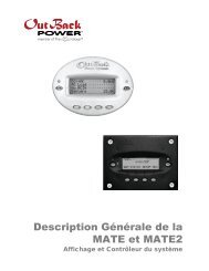
Radian Series Inverter/Charger<br />
<strong>GS8048</strong><br />
<strong>Installation</strong> <strong>Manual</strong>
About <strong>OutBack</strong> <strong>Power</strong> <strong>Technologies</strong><br />
<strong>OutBack</strong> <strong>Power</strong> <strong>Technologies</strong> is a leader in advanced energy conversion technology. <strong>OutBack</strong><br />
products include true sine wave inverter/chargers, maximum power point tracking charge controllers,<br />
and system communication components, as well as circuit breakers, accessories, and<br />
assembled systems.<br />
Contact Information<br />
Telephone: +1.360.435.6030<br />
+1.360.618.4363 (Technical Support)<br />
+1.360.435.6019 (Fax)<br />
Mailing Address:<br />
(North America)<br />
<strong>OutBack</strong> <strong>Power</strong> <strong>Technologies</strong><br />
5917 – 195 th Street N.E., #7<br />
Arlington, WA 98223 USA<br />
Address:<br />
Sales, Marketing, & Warranty<br />
6115 – 192nd Street NE<br />
Arlington, WA 98223 USA<br />
E-mail:<br />
Support@outbackpower.com<br />
Web Site:<br />
www.outbackpower.com<br />
Disclaimer<br />
UNLESS SPECIFICALLY AGREED TO IN WRITING, OUTBACK POWER TECHNOLOGIES:<br />
(a) MAKES NO WARRANTY AS TO THE ACCURACY, SUFFICIENCY OR SUITABILITY OF ANY TECHNICAL<br />
OR OTHER INFORMATION PROVIDED IN ITS MANUALS OR OTHER DOCUMENTATION.<br />
(b) ASSUMES NO RESPONSIBILITY OR LIABILITY FOR LOSS OR DAMAGE, WHETHER DIRECT, INDIRECT,<br />
CONSEQUENTIAL OR INCIDENTAL, WHICH MIGHT ARISE OUT OF THE USE OF SUCH INFORMATION. THE<br />
USE OF ANY SUCH INFORMATION WILL BE ENTIRELY AT THE USER’S RISK.<br />
Warranty Summary<br />
<strong>OutBack</strong> <strong>Power</strong> <strong>Technologies</strong> Inc. warrants that the products it manufactures will be free from defects<br />
in materials and workmanship for a period of five (5) years subject to the conditions set forth in the<br />
warranty detail, found in the Radian Series Inverter/Charger Operator’s <strong>Manual</strong>.<br />
<strong>OutBack</strong> <strong>Power</strong> <strong>Technologies</strong> cannot be responsible for system failure, damages, or injury resulting<br />
from improper installation of their products.<br />
Notice of Copyright<br />
Radian Series Inverter/Charger <strong>Installation</strong> <strong>Manual</strong> © August 2011 by <strong>OutBack</strong> <strong>Power</strong> <strong>Technologies</strong>.<br />
All Rights Reserved.<br />
Trademarks<br />
<strong>OutBack</strong> <strong>Power</strong> is a registered trademark of <strong>OutBack</strong> <strong>Power</strong> <strong>Technologies</strong>.<br />
Date and Revision<br />
August 2011, Revision A<br />
Part Number<br />
900-0021-01-00 Rev A
Important Safety Instructions<br />
READ AND SAVE THESE INSTRUCTIONS!<br />
This manual contains important safety instructions for the Radian Series Inverter/Charger. Read all<br />
instructions and cautionary markings on the inverter and on any accessories or additional equipment<br />
included in the installation. Failure to adhere to these instructions could result in severe shock or<br />
possible electrocution. Exercise extreme caution at all times to prevent accidents.<br />
Audience<br />
These instructions are for use by qualified personnel who meet all local and governmental code<br />
requirements for licensing and training for the installation of electrical power systems with AC and DC<br />
voltage up to 600 volts.<br />
Symbols Used<br />
Symbol<br />
Description<br />
Ground<br />
AC Current<br />
DC Current<br />
<br />
Single-Phase<br />
Sine Wave<br />
WARNING: Hazard to Human Life<br />
This type of notation indicates that the hazard could be harmful to human life.<br />
CAUTION: Hazard to Equipment<br />
This type of notation indicates that the hazard may cause damage to the equipment.<br />
IMPORTANT:<br />
This type of notation indicates that the information provided is important to<br />
the installation, operation and/or maintenance of the equipment. Failure to<br />
follow the recommendations in such a notation could result in voiding the<br />
equipment warranty.<br />
900-0021-01-00 Rev A 1
Important Safety Instructions<br />
Definitions<br />
The following is a list of initials, terms, and definitions used with this product.<br />
Table 1<br />
Terms and Definitions<br />
Term<br />
12V AUX<br />
AC<br />
AGS<br />
CSA<br />
DC<br />
DVM<br />
ETL<br />
GFDI<br />
GND<br />
Grid-interactive,<br />
grid-intertie, grid-tie<br />
GSLC<br />
HBX<br />
IEEE<br />
LBCO<br />
MATE3<br />
NEC<br />
NEU<br />
Off-grid<br />
PV<br />
RELAY AUX<br />
RTS<br />
Split-phase<br />
Definition<br />
Auxiliary connection that supplies 12 Vdc to control external devices.<br />
Alternating Current; refers to voltage produced by the inverter, utility grid, or generator<br />
Advanced Generator Start<br />
Canadian Standards Association; establishes Canadian national standards and the<br />
Canadian Electrical Code, including C22.1 and C22.2<br />
Direct Current; refers to voltage produced by the batteries or renewable source<br />
Digital Voltmeter<br />
Electrical Testing Laboratories; short for the company ETL Semko; refers to a certification<br />
issued by ETL to <strong>OutBack</strong> products indicating that they meet certain UL standards<br />
Ground Fault Detector Interruptor; a safety device for PV systems<br />
Ground; a permanent conductive connection to earth for safety reasons; also known as<br />
Chassis Ground, Protective Earth, PE, Grounding Electrode Conductor, and GEC<br />
Utility grid power is available for use and the inverter is a model capable of returning<br />
(selling) electricity back to the utility grid<br />
GS Load Center; the wiring box for the Radian (GS) inverter<br />
High Battery Transfer; a function of the MATE3<br />
Institute of Electrical and Electronics Engineers; refers to a series of standards and<br />
practices for the testing of electrical products<br />
Low Battery Cut-Out; set point at which the inverter shuts down due to low voltage<br />
A system display, used for monitoring, programming and communicating with the<br />
inverter<br />
National Electric Code<br />
AC Neutral; also known as Common<br />
Utility grid power is not available for use<br />
Photovoltaic<br />
Auxiliary connection that uses switch (relay) contacts to control external devices.<br />
Remote Temperature Sensor; accessory that measures battery temperature for charging<br />
A type of utility electrical system with 2 “hot” lines that are 120 Vac with respect to<br />
neutral and 240 Vac between the “hot” lines; common in North America<br />
2 900-0021-01-00 Rev A
Important Safety Instructions<br />
Table 1<br />
Terms and Definitions<br />
Term<br />
System display<br />
UL<br />
Utility grid<br />
Definition<br />
Remote interface device (such as the MATE3), used for monitoring, programming and<br />
communicating with the inverter; also called “remote system display”<br />
Underwriters Laboratories; refers to a set of safety standards governing electrical<br />
products<br />
The electrical service and infrastructure supported by the electrical or utility company;<br />
also called “mains”, “utility service”, or “grid”<br />
General Safety<br />
WARNING: Limitations on Use<br />
This equipment is NOT intended for use with life support equipment or other medical<br />
equipment or devices.<br />
CAUTION: Equipment Damage<br />
Only use components or accessories recommended or sold by <strong>OutBack</strong> <strong>Power</strong><br />
<strong>Technologies</strong> or its authorized agents.<br />
IMPORTANT:<br />
Personal Safety<br />
Do not attempt to install this equipment if it appears to be damaged in any way. See<br />
the Warranty section for instructions on returning the equipment.<br />
WARNING: Personal Injury<br />
‣ This equipment weighs in excess of 125 lbs (57 kg). Use safe lifting techniques<br />
when lifting this equipment as prescribed by the Occupational Safety and Health<br />
Association (OSHA) or other local codes.<br />
‣ Use standard safety equipment such as safety glasses, ear protection, steel-toed<br />
safety boots, safety hard hats, etc., as prescribed by the Occupational Safety and<br />
Health Association (or other local codes) when working on this equipment.<br />
‣ Use standard safety practices when working with electrical equipment (e.g., remove<br />
all jewelry, use insulated tools, wear cotton clothing, etc.).<br />
‣ Never work alone when installing or servicing this equipment. Have someone<br />
nearby that can assist if necessary.<br />
900-0021-01-00 Rev A 3
Important Safety Instructions<br />
Inverter Safety<br />
WARNING: Lethal Voltage<br />
‣ Review the system configuration to identify all possible sources of energy. Ensure<br />
ALL sources of power are disconnected before performing any installation or<br />
maintenance on this equipment. Confirm that the terminals are de-energized using<br />
a validated voltmeter (rated for a minimum 1000 Vac and 1000 Vdc) to verify the deenergized<br />
condition.<br />
‣ Do not perform any servicing other than that specified in the installation<br />
instructions unless qualified to do so, or have been instructed to do so by <strong>OutBack</strong><br />
<strong>Power</strong> <strong>Technologies</strong> Technical Support personnel.<br />
WARNING: Burn Hazard<br />
Internal parts can become hot during operation. Do not remove the cover during<br />
operation or touch any internal parts. Be sure to allow sufficient time for internal parts<br />
to cool down before attempting to perform any maintenance.<br />
WARNING: Fire Hazard<br />
‣ Do not place combustible or flammable materials within 12 feet (3.7 m) of<br />
the equipment.<br />
‣ This product contains relays with moving parts and is not ignition-protected.<br />
‣ Ensure AC, DC, and ground cable sizes conform to local codes. See pages 24<br />
through 26 for minimum size requirements. Ensure all conductors are in good<br />
condition. Do not operate the unit with damaged or substandard cabling.<br />
CAUTION: Equipment Damage<br />
When connecting cables from the inverter to the battery terminals, ensure the proper<br />
polarity is observed. Connecting the cables incorrectly can damage or destroy the<br />
equipment and void the product warranty.<br />
CAUTION: Equipment Damage<br />
‣ Thoroughly inspect the equipment prior to energizing. Verify that no tools or<br />
equipment have been inadvertently left behind.<br />
‣ Ensure clearance requirements are strictly enforced. Keep all vents clear of<br />
obstructions that can prevent proper air flow around, or through, the unit.<br />
‣ Sensitive electronics inside the equipment can be destroyed by static electricity. Be<br />
sure to discharge any static electricity before touching the equipment and wear<br />
appropriate protective gear.<br />
4 900-0021-01-00 Rev A
Important Safety Instructions<br />
Battery Safety<br />
WARNING: Explosion, Electrocution, or Fire Hazard<br />
‣ Use the battery types recommended by <strong>OutBack</strong> <strong>Power</strong> <strong>Technologies</strong>. Follow the<br />
battery manufacturer’s recommendations for installation and maintenance.<br />
‣ Ensure the cables are properly sized. Failure to size the cables properly can result in<br />
a fire hazard.<br />
‣ Ensure clearance requirements are strictly enforced around the batteries.<br />
‣ Ensure the area around the batteries is well ventilated and clean of debris.<br />
‣ Never smoke near, or allow a spark or flame near, the batteries.<br />
‣ Always use insulated tools. Avoid dropping tools onto batteries or other<br />
electrical parts.<br />
‣ Keep plenty of fresh water and soap nearby in case battery acid contacts skin,<br />
clothing, or eyes.<br />
‣ Wear complete eye and clothing protection when working with batteries. Avoid<br />
touching bare skin or eyes while working near batteries.<br />
‣ If battery acid contacts skin or clothing, wash immediately with soap and water. If<br />
acid enters the eye, immediately flood it with running cold water for at least<br />
20 minutes and get medical attention as soon as possible.<br />
‣ Never charge a frozen battery.<br />
‣ Insulate batteries as appropriate against freezing temperatures. A discharged<br />
battery will freeze more easily than a charged one.<br />
‣ If a battery must be removed, always remove the grounded terminal from the<br />
battery first. Make sure all devices are de-energized or disconnected to avoid<br />
causing a spark.<br />
‣ If a remote or automatic generator control system is used, disable the starting<br />
circuit and/or disconnect the generator from its starting battery while performing<br />
maintenance to prevent accidental starting.<br />
IMPORTANT:<br />
Baking Soda neutralizes lead-acid battery electrolyte.<br />
Vinegar neutralizes NiCad and NiFe battery electrolyte.<br />
Have a supply of either substance readily available if using these types of batteries.<br />
900-0021-01-00 Rev A 5
Additional Information<br />
Regulatory Specifications<br />
See the Radian Series Inverter/Charger Operator’s <strong>Manual</strong> for all specifications and regulatory<br />
information, including certifications.<br />
Required Resources<br />
This product is required to be installed according to pertinent safety codes and standards. If installed<br />
in the United States, wiring practices must meet the requirements of the National Electrical Code<br />
(NEC). If installed in Canada, wiring practices must meet the requirements of the Canadian<br />
Electrical Code.<br />
‣ National Electrical Code (NEC)/NFPA 70, Current Edition<br />
‣ Canadian Electrical Code, C22.1, Current Edition<br />
Additional Resources<br />
The following are references which may be used when installing this equipment. Depending on the<br />
nature of the installation, it may be highly recommended to consult any or all of these resources.<br />
‣ National Electrical Code (NEC)/NFPA 70 Handbook, Current Edition<br />
‣ UL 1741, Current Edition, Static Inverter and Charge Controllers for Use in Photovoltaic <strong>Power</strong> Systems<br />
‣ International Building Code (IBC), Current Edition<br />
‣ Photovoltaic <strong>Power</strong> Systems and the 2005 National Electrical Code: Suggested Practices<br />
6 900-0021-01-00 Rev A
Additional Information<br />
Recycling Information<br />
Earth 911, USA<br />
IMPORTANT: Recycle Electronics and Batteries<br />
Batteries are considered hazardous waste and must be recycled according to<br />
local jurisdiction. Inverters and other electronics contain metals and plastics<br />
that should also be recycled. The following web sites and phone numbers<br />
provide additional information for recycling electronic products and batteries.<br />
Web site: www.Earth911.com<br />
Address: 14646 N. Kierland Blvd., Suite 100<br />
Scottsdale, AZ 85254<br />
Phone: +1.480.337.3025 (direct)<br />
Environmental Protection Agency, USA<br />
Web site: www.epa.gov/recyclecity/<br />
Email: r9.recyclecity@epa.gov<br />
Phone: +1.415.947.8000<br />
(Monday –Friday 8:00 AM to 12:00 PM and 1:00 PM to 4:00 PM PST)<br />
Keep America Beautiful, USA<br />
Web site: www.kab.org/<br />
Email: info@kab.org<br />
Address: 1010 Washington Boulevard<br />
Stamford, CT 06901<br />
Phone: +1.203.659.3000 (Main number)<br />
Fax: +1.203.659.3001<br />
OurEarth.org, USA<br />
There is a place on the website for contacting OurEarth.org using email. No direct email address<br />
is provided.<br />
Web site: http://www.ourearth.org<br />
Address: P.O. Box 62133<br />
Durham, NC 27715<br />
Phone: +1.410.878.6485<br />
National Institute of Recyclers, Mexico<br />
Web site: http://www.inare.org.mx/<br />
Email: a57841279@prodigy.net.mx, margarita@inare.org.mx<br />
Phone: +1.55.57.85.9160<br />
Fax: +1.55.57.84.1279<br />
900-0021-01-00 Rev A 7
Additional Information<br />
Natural Resources Canada<br />
Address: 580 Booth, Ottawa, ON K1A 0E8<br />
Web site: http://www.nrcan-rncan.gc.ca/mms-smm/busi-indu/rec-rec-eng.htm<br />
Phone: +1.613.995.0947<br />
TTY: +1.613.996.4397<br />
(Phone and TTY: Monday to Friday, 8:30 a.m. to 4:30 p.m. ET)<br />
Office of Waste Management, Canada<br />
Web site: http://www.portaec.net/library/recycling/recycling_in_canada.html<br />
Address: Office of Waste Management<br />
Conservation and Protection<br />
Environment Canada<br />
Ottawa, Ontaro K1A 0H3<br />
Phone: +1.819.997.2800<br />
EuroRecycle.net, Europe<br />
The following website provides general information about recycling in Europe. It also provides a list of<br />
companies and organizations that provide recycling information or assistance.<br />
Web site:<br />
E-mail:<br />
http://euro.recycle.net<br />
http://euro.recycle.net/cgi-bin/feedback1.cgiw=27<br />
(This is an online form providing a means to contact the owners of the website.)<br />
8 900-0021-01-00 Rev A
Table of Contents<br />
Important Safety Instructions ........................................................................1<br />
Audience .................................................................................................................................................................................1<br />
Symbols Used ........................................................................................................................................................................1<br />
Definitions...............................................................................................................................................................................2<br />
General Safety .......................................................................................................................................................................3<br />
Personal Safety......................................................................................................................................................................3<br />
Inverter Safety .......................................................................................................................................................................4<br />
Battery Safety.........................................................................................................................................................................5<br />
Regulatory Specifications..................................................................................................................................................6<br />
Required Resources .............................................................................................................................................................6<br />
Additional Resources ..........................................................................................................................................................6<br />
Recycling Information ........................................................................................................................................................7<br />
Introduction...............................................................................................11<br />
Welcome to <strong>OutBack</strong> <strong>Power</strong> <strong>Technologies</strong>.............................................................................................................. 11<br />
Components and Accessories ...................................................................................................................................... 12<br />
Planning ....................................................................................................13<br />
Applications ........................................................................................................................................................................ 13<br />
Renewable Energy ............................................................................................................................................................ 14<br />
Battery Bank ........................................................................................................................................................................ 14<br />
Generator ............................................................................................................................................................................. 15<br />
Maintenance Bypass Switching ................................................................................................................................... 16<br />
<strong>Installation</strong> .................................................................................................17<br />
Location and Environmental Requirements............................................................................................................ 17<br />
Dimensions.......................................................................................................................................................................... 17<br />
Tools Required.................................................................................................................................................................... 18<br />
Mounting.............................................................................................................................................................................. 18<br />
Accessory Mounting .....................................................................................................................................................................20<br />
Removing Front Cover .................................................................................................................................................... 21<br />
Terminals and Ports.......................................................................................................................................................... 22<br />
Grounding............................................................................................................................................................................ 24<br />
DC Wiring ............................................................................................................................................................................ 25<br />
AC Wiring.............................................................................................................................................................................. 26<br />
AC Sources........................................................................................................................................................................................27<br />
Accessory Wiring ............................................................................................................................................................... 28<br />
AUX Wiring .......................................................................................................................................................................... 29<br />
Automatic Generator Start (AGS) .............................................................................................................................................31<br />
Single-Inverter AC <strong>Installation</strong>s.................................................................................................................................... 34<br />
Multiple-Inverter AC <strong>Installation</strong>s (Stacking)........................................................................................................... 35<br />
Functional Test................................................................................................................................................................... 38<br />
Index .........................................................................................................39<br />
900-0021-01-00 Rev A 9
Table of Contents<br />
List of Tables<br />
Table 1 Terms and Definitions...................................................................................................................... 2<br />
Table 2 Components and Accessories ....................................................................................................12<br />
Table 3 Ground Conductor Size and Torque Requirements ..........................................................24<br />
Table 4 DC Conductor Size and Torque Requirements....................................................................25<br />
List of Figures<br />
Figure 1 <strong>GS8048</strong> Inverter/Charger .............................................................................................................11<br />
Figure 2 Radian Inverter and Accessories................................................................................................12<br />
Figure 3 Applications (Example) .................................................................................................................13<br />
Figure 4 Bypass Switching.............................................................................................................................16<br />
Figure 5 Bypass Switching for Multiple Inverters .................................................................................16<br />
Figure 6 Dimensions........................................................................................................................................17<br />
Figure 7 Mounting the Inverter...................................................................................................................18<br />
Figure 8 Mounting the Inverter (continued) ..........................................................................................19<br />
Figure 9 Mounting for Accessories ............................................................................................................20<br />
Figure 10 Cover Screws.....................................................................................................................................21<br />
Figure 11 Terminals, Ports, and Features ...................................................................................................22<br />
Figure 12 Terminals, Ports, and Features (continued) .........................................................................23<br />
Figure 13 Chassis Ground TBB........................................................................................................................24<br />
Figure 14 DC Cable Hardware (underside of inverter)..........................................................................25<br />
Figure 15 AC Terminals .....................................................................................................................................26<br />
Figure 16 AC Sources .........................................................................................................................................27<br />
Figure 17 Accessory Connections.................................................................................................................28<br />
Figure 18 ON/OFF Jumper and Connections............................................................................................28<br />
Figure 19 AUX Connections for Vent Fan (Example) .............................................................................29<br />
Figure 20 AUX Connections for Diversion (Example) ............................................................................30<br />
Figure 21 Two-Wire Generator Start (RELAY AUX) .................................................................................31<br />
Figure 22 Two-Wire Generator Start (12V AUX).......................................................................................32<br />
Figure 23 Three-Wire Generator Start (Example)....................................................................................33<br />
Figure 24 Single-Inverter Wiring ...................................................................................................................34<br />
Figure 25 <strong>OutBack</strong> HUB4 and MATE3 .........................................................................................................35<br />
Figure 26 Example of Parallel Stacking Arrangement (Three Inverters) ........................................36<br />
Figure 27 Parallel Wiring...................................................................................................................................37<br />
10 900-0021-01-00 Rev A
Welcome to <strong>OutBack</strong> <strong>Power</strong> <strong>Technologies</strong><br />
Introduction<br />
Thank you for purchasing the <strong>OutBack</strong> Radian Series Inverter/Charger. This product offers a complete<br />
power conversion system between batteries and AC power. It can provide backup power, sell power<br />
back to the utility grid, or provide complete stand-alone off-grid service.<br />
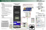
Mounts easily with supplied mounting plate.<br />
All terminals exit at the bottom of the inverter.<br />
This allows the installer to use a single distribution<br />
box. The GS Load Center (GSLC) is specifically<br />
designed for this purpose and is sold separately.<br />
Uses spring-based AC terminals instead of<br />
screw-based terminals. This eliminates torque<br />
requirements and periodic re-tightening.<br />
Uses the MATE3 System Display and Controller<br />
(sold separately) for user interface.<br />
Features versatile mounting locations for the<br />
MATE3, HUB, and FLEXmax products, as well as<br />
the GSLC.<br />
The venting on the cover allows mounting of<br />
multiple Radian inverter/chargers side by side<br />
with zero clearance required between them.<br />
Up to 10 Radian Series Inverter/Chargers can be<br />
stacked together.<br />
Figure 1<br />
<strong>GS8048</strong> Inverter/Charger<br />
IMPORTANT:<br />
This product is not compatible with the <strong>OutBack</strong> MATE or MATE2 System Display and<br />
Controller. Use of these products is not supported with the Radian Series.<br />
900-0021-01-00 Rev A 11
Introduction<br />
Components and Accessories<br />
Table 2<br />
Components and Accessories<br />
Radian Series <strong>Installation</strong> <strong>Manual</strong> (this book)<br />
Radian Series Operator’s <strong>Manual</strong><br />
Mounting Bracket<br />
Included in Box<br />
RTS (Remote Temperature Sensor)<br />
Hardware Kit<br />
Optional Components for Attachment to Radian Inverter<br />
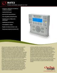
MATE3 System Display and Controller<br />
FW-MB3 (MATE3 bracket)<br />
GSLC, GSLC175-120/240, or GSLC-PV-120-/240<br />
(GS Load Centers)<br />
FLEXmax 60 or FLEXmax 80 Charge Controller<br />
FW-CCB or FW-CCB2 (charge controller brackets)<br />
<strong>OutBack</strong> HUB4 or HUB10<br />
MATE3<br />
FLEXmax<br />
Charge Controllers<br />
HUB<br />
GSLC<br />
Figure 2<br />
Radian Inverter and Accessories<br />
12 900-0021-01-00 Rev A
Planning<br />
Applications<br />
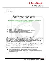
The Radian Series Inverter/Charger is intended for both grid-interactive and off-grid applications.<br />
These inverters are designed to use a battery bank to store energy. They can work in conjunction with<br />
photovoltaic (PV) panels to harvest solar energy, as well as wind turbines and other renewable<br />
sources. These sources charge the battery, which in turn is used by the inverter.<br />
Figure 3<br />
Applications (Example)<br />
The Radian inverter has six modes of operation. Each mode has functions and priorities that are<br />
intended for a designated application. Each of the Radian’s two AC inputs can be set to a different<br />
operating mode, so that different applications can be supported.<br />
NOTE: See the Radian Series Inverter/Charger Operator’s <strong>Manual</strong> for additional information on these<br />
modes, including the benefits of using each mode.<br />
Generator: This mode is intended for an AC generator. It is designed to accept any AC generator regardless<br />
of power or regulation mechanism. The Radian will charge from the generator even when the generator is<br />
undersized or substandard.<br />
Support: This mode is intended for systems that use the utility grid or a generator. However, size, wiring, or<br />
other limitations may require temporary assistance to run very large loads. The Radian adds inverter and<br />
battery power to the AC source to ensure that the loads receive the power they require.<br />
Grid Tied: This mode is intended for grid-interactive systems. When renewable energy sources charge the<br />
batteries above a selected “target” voltage, the Radian inverter will send the excess energy to any loads. If<br />
the loads do not use all the excess energy, then the Radian will return that energy to the utility grid.<br />
UPS (Uninterruptible <strong>Power</strong> Supply): This mode is intended for systems whose main focus is to maintain<br />
power to the loads without any interruption during a transfer to, or from, the AC input. The transfer speed<br />
in this mode has been reduced so that if the AC input power is disconnected or a scheduled disconnect<br />
occurs the transfer speed will be less than 4 milliseconds.<br />
900-0021-01-00 Rev A 13
Planning<br />
‣ Backup: This mode is intended for systems that have the utility grid available. This source will flow through<br />
the Radian inverter to power the loads unless utility power is lost. If utility grid power is lost, then the Radian<br />
inverter will supply energy to the loads from the battery bank until the power is back online.<br />
‣ Minigrid: This mode is intended for systems that have the utility grid as an input and a sizable amount of<br />
renewable energy production. The system will run off the renewable energy production until the battery<br />
voltage falls to a specified low level. When this occurs, the Radian inverter will connect to the utility grid,<br />
which will power the loads. The Radian inverter will disconnect from the utility grid when the batteries are<br />
sufficiently recharged.<br />
Renewable Energy<br />
The Radian Series Inverter/Charger cannot connect directly to photovoltaic arrays, wind turbines, or<br />
other renewable sources. The batteries are the inverter’s primary source of power. However, if these<br />
sources are used to charge the batteries, the inverter can use their energy by drawing it from the<br />
batteries.<br />
The renewable source is always treated as a battery charger, even if all of its power is used<br />
immediately. The renewable source must have a charge controller or some way to prevent<br />
overcharging. <strong>OutBack</strong> <strong>Power</strong>’s FLEXmax charge controllers can be used for this purpose, as can<br />
other products. The GSLC will facilitate the mechanical and electrical connections for up to two<br />
FLEXmax charge controllers.<br />
Battery Bank<br />
When planning a battery bank, consider the following:<br />
‣ Cables: Recommendations for battery cable size and length are shown on page 25. The maximum length<br />
will determine the placement of the battery bank. Other local codes or regulations may apply and may take<br />
priority over <strong>OutBack</strong> recommendations.<br />
‣ Battery Type: The Radian inverter/charger works best with lead-chemistry batteries intended for deep<br />
discharge. These include batteries for marine, golf-cart, and forklift applications. They also include gel-cell<br />
batteries and absorbed glass-mat (AGM) batteries. <strong>OutBack</strong> <strong>Power</strong> recommends the use of batteries<br />
designed specifically for renewable energy applications. Automotive batteries are strongly discouraged and<br />
will have a short life if used in inverter applications. Nickel-based batteries are discouraged due to<br />
limitations in the Radian charger. Lithium-based batteries and other advanced battery technologies may<br />
require special considerations. Please contact <strong>OutBack</strong> Technical Support at +1.360.618.4363 before<br />
implementing advanced battery technologies.<br />
‣ The Radian inverter/charger is designed to work with a 48-volt battery bank. Before constructing a battery<br />
bank, confirm the nominal voltage of individual batteries.<br />
‣ Bank Size: In backup or off- grid applications, the battery bank size should be calculated based on<br />
expected loads and run time.<br />
~ To prevent the inverter’s charger from overcharging, the minimum recommended battery bank size is<br />
350 amp-hours for every Radian inverter/charger installed on the system.<br />
~ If other charging devices are present, the minimum bank size should be determined by adding the<br />
inverter(s) charge rate to any other chargers and multiplying the result by five. Example: If the system’s<br />
combined charge rate was 160 Adc, the minimum battery bank size should be 800 amp-hours.<br />
‣ Systems intended to bridge short-term outages can use smaller battery banks. In these cases, the bank can<br />
be as low as 200 amp-hours per inverter. However, the charge rate must be decreased to half the inverter’s<br />
maximum using the MATE3. (See the MATE3 manual.) One of the following conditions must also be true.<br />
~ The system is equipped with a backup generator that is programmed for automatic start, or<br />
~ Typical grid loss is 30 minutes or less, or<br />
~ The loads are less than 2 kW.<br />
14 900-0021-01-00 Rev A
Planning<br />
NOTE: If support time or load size are disproportionate to the bank size, they will cause inverter shutdown<br />
due to low battery voltage after a short time. These conditions could be detrimental to the life of a small<br />
battery bank. If this is true, the recommendations from the previous page apply instead.<br />
‣ Charger Settings and Maintenance: A vented enclosure for the battery bank may be required by electric<br />
code and is recommended in most cases for safety reasons. It may be necessary to use a fan to ventilate the<br />
battery enclosure. (See the Operator’s <strong>Manual</strong> for vent fan applications.)<br />
‣ Batteries must be regularly maintained according to the instructions of the battery manufacturer.<br />
Generator<br />
The Radian inverter/charger has specific connections for a “split-phase” generator. It can work with<br />
any generator that delivers clean 120/240 Vac at 60 Hz. This product cannot work with a single-phase<br />
or three-phase generator.<br />
‣ The Radian inverter/charger can provide a start signal to control an automatic start generator. If automatic<br />
generator starting is required, the generator must be an electric-start model with automatic choke and<br />
two-wire start capability. (See page 31.) For other configurations, additional equipment may be required.<br />
‣ In all cases, the inverter may need to be programmed using the MATE3 according to the specifications of<br />
the generator and the requirements of the system. (See the Radian Series Inverter/Charger Operator’s <strong>Manual</strong><br />
and the MATE3 Owner’s <strong>Manual</strong>.) Parameters to be programmed may include generator size, automatic<br />
starting requirements, and potential fluctuations in generator AC voltage.<br />
Generator Sizing<br />
IMPORTANT:<br />
Battery charger settings need to be correct for a given battery type. Always follow<br />
battery manufacturer recommendations. Making incorrect settings, or leaving them at<br />
factory default settings, may cause the batteries to be undercharged or overcharged.<br />
CAUTION: Hazard to Equipment<br />
Batteries can emit hydrogen sulfide gas which is corrosive over long periods of time.<br />
Installing the inverter in the battery compartment may cause corrosion which is not<br />
covered by the product warranty. (Sealed batteries may be an exception.)<br />
A generator should be sized to provide enough power for all the loads and the battery charger.<br />
‣ Available generator power may be limited by ratings for circuit breakers and/or generator connectors. The<br />
maximum allowed AC circuit breaker size is 50 Aac per Radian inverter/charger.<br />
‣ The generator must be able to provide current to all inverters. Minimum generator wattage 1 is usually<br />
recommended to be twice the wattage of the inverter system. Many generators may not be able to<br />
maintain AC voltage or frequency for long periods of time if they are loaded more than 80% of rated<br />
capacity.<br />
‣ A generator that is to be installed in a building should not have a bond between the neutral and ground<br />
connections. <strong>Installation</strong>s in North America are expected to bond the neutral and ground at the main<br />
electrical panel.<br />
1<br />
This is the wattage value after de-ratings for peak versus continuous power, for load power factor considerations, for fuel<br />
type, for altitude, and for ambient temperature.<br />
900-0021-01-00 Rev A 15
Planning<br />
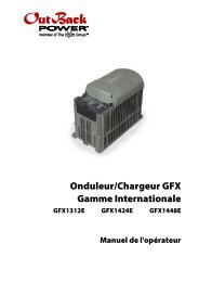
Maintenance Bypass Switching<br />
Inverter systems are often equipped with AC maintenance bypass switches or interlocks. If the<br />
inverter system ever needs to be shut down or removed, the AC sources and loads must be<br />
disconnected. A bypass device allows the AC source to deliver power directly to the loads, bypassing<br />
the inverter. This can minimize disruption to the system and avoids the need for extensive rewiring.<br />
Inoperative<br />
Radian<br />
Inverter<br />
AC Loads<br />
GSLC Bypass<br />
AC Source<br />
Input Wiring<br />
Output Wiring<br />
Figure 4<br />
Bypass Switching<br />
The GSLC (see page 12) can be equipped with bypass circuit breakers for this purpose. However, if<br />
multiple Radian inverters are stacked in a single system, then the bypass function must be<br />
simultaneous for all inverters. The GSLC bypass kits operate independently, not simultaneously, and<br />
should not be installed in this kind of application. Both manual and automatic double-pole,<br />
double-throw bypass switches are commonly available in a range of sizes and options. These are<br />
highly recommended for systems with more than a single inverter.<br />
WARNING: Shock Hazard or Equipment Damage<br />
Using independent bypass devices on multiple inverters can result in power being routed<br />
to inappropriate places. This could create an electric shock hazard or damage the<br />
equipment.<br />
Input Wiring<br />
External Bypass Device<br />
Output Wiring<br />
Inactive Radian Inverters<br />
AC Source<br />
AC Loads<br />
GSLC Bypass Devices<br />
(not to be used)<br />
Figure 5<br />
Bypass Switching for Multiple Inverters<br />
16 900-0021-01-00 Rev A
Location and Environmental Requirements<br />
<strong>Installation</strong><br />
Radian Series Inverter/Chargers must be located in a weather-proof enclosure or enclosed area. It is<br />
not designed for exposure to water or excessive wind-blown dust and debris.<br />
‣ The Radian inverter must be wall-mounted in an upright position. The inverter is not approved for<br />
mounting in any other position or orientation.<br />
‣ Recommended minimum clearance is 2 to 4 inches (5 to 10 cm) for the front and top of the inverter.<br />
‣ The sides and bottom may be enclosed or obscured with no restriction when mounting other Radian Series<br />
Inverter/Chargers or accessory devices.<br />
‣ The Radian inverter will function best if operated in a temperature range of 0°C to 50°C (32°F to 122°F).<br />
It can function in environments as cold as –40°C (–40°F) and as warm as 60°C (140°F), but it may not update<br />
up to its listed specifications.<br />
‣ The specifications are listed in the Radian Series Inverter/Charger Operator’s <strong>Manual</strong>.<br />
Dimensions<br />
Width 16” (40.6 cm)<br />
Depth<br />
8.75” (22 cm)<br />
Enclosure Height<br />
28” (71.1 cm)<br />
Enclosure<br />
Height with<br />
Flange<br />
29.13”<br />
(74 cm)<br />
Figure 6<br />
Dimensions<br />
900-0021-01-00 Rev A 17
<strong>Installation</strong><br />
Tools Required<br />
The following tools may be required for this installation:<br />
‣ Wire cutters/strippers<br />
‣ Assorted torque wrenches, ratchet wrenches, and sockets<br />
(metric and standard)<br />
Mounting<br />
‣ Assorted insulated screwdrivers<br />
‣ DVM or Voltmeter<br />
‣ At least two people are needed to install the Radian inverter/charger due to its weight.<br />
‣ Mount and secure each component before attaching any wiring. The bottom of the inverter must be<br />
enclosed to meet NEC requirements. The GSLC was specifically designed for this purpose.<br />
‣ Avoid large air gaps behind the Radian inverter/charger and its mounting plate. These can result in louder<br />
mechanical noise during heavy inverting or charging. Mount the plate on a flat, solid mounting surface.<br />
IMPORTANT:<br />
Use correct fasteners to secure the mounting plate and the Radian inverter/charger to the<br />
mounting surface. <strong>OutBack</strong> cannot be responsible for damage to the product if it is attached<br />
with inadequate fasteners.<br />
The Radian inverter/charger comes equipped with a mounting plate, as shown in Figure 7.<br />
The Radian inverter is mounted using<br />
these steps.<br />
1. The mounting plate is to be screwed<br />
or bolted directly to a solid<br />
mounting surface such as wall studs.<br />
(See Figure 7.) Lag screws are<br />
provided for this purpose.<br />
~ The plate will span wall studs<br />
on 16-inch centers. If the studs<br />
have larger spacing than 16<br />
inches, it is recommended that<br />
plywood or similar material be<br />
installed over the studs. The<br />
mounting plate can be installed<br />
on the plywood surface.<br />
~ If multiple Radian<br />
inverter/chargers are being<br />
installed, all mounting plates<br />
should be installed first. The<br />
inverters can be mounted and<br />
secured one at a time when this<br />
is done.<br />
16” Center Studs<br />
Mounting Plate<br />
Continued on the next page…<br />
Figure 7<br />
Mounting the Inverter<br />
18 900-0021-01-00 Rev A
<strong>Installation</strong><br />
GS Inverter<br />
xx<br />
2. Place the Radian inverter against the wall and slide it directly<br />
over the upper lip of the mounting plate. The inverter’s<br />
mounting flange should come to rest within the lip so that it<br />
hangs securely.<br />
Because the inverter’s mounting flange is difficult to see,<br />
dimples have been placed on the side of the unit to mark the<br />
lower edge of the flange. In the picture to the left, the two X<br />
symbols show the location of the dimples.<br />
Mounting Plate<br />
3. Align the left edge of the inverter with the left edge of the<br />
mounting plate. This will expose the right edge of the plate,<br />
allowing easy installation of another Radian inverter/charger in<br />
the future. All additional inverters are mounted to the right of<br />
the existing unit.<br />
The unit shown to the right is not aligned with the mounting<br />
plate, as the plate is still visible. In this example, it should slide<br />
to the left so that the plate is entirely covered.<br />
NOTE: If the GSLC is used with the Radian inverter, the<br />
following step should be omitted.<br />
4. Once aligned, secure the Radian inverter to the stud using a lag<br />
screw (provided) in the left corner of the inverter’s bottom<br />
flange. Securing the inverter this way will prevent it from<br />
dislodging from the mounting plate in the event of an<br />
earthquake or similar event.<br />
NOTE: The left corner is used for securing the inverter to a stud.<br />
If the Radian inverter is mounted on plywood or a similar<br />
wide-area mounting surface as shown, any of the slots in the<br />
mounting flange may be used.<br />
WARNING: Shock Hazard<br />
When the inverter is used with other metal chassis, make sure that all chassis are<br />
grounded appropriately. (See the grounding instructions on page 23.) Grounding other<br />
chassis may involve metal-to-metal contact, or separate ground wires.<br />
Figure 8<br />
Mounting the Inverter (continued)<br />
900-0021-01-00 Rev A 19
<strong>Installation</strong><br />
Accessory Mounting<br />
The Radian inverters can support the mounting of<br />
several accessories. The inverter can mount the<br />
MATE3 system display and the HUB on its left side, and<br />
up to two FLEXmax controllers on its right side.<br />
The FLEXmax controllers and the HUB products can<br />
also mount on the sides of the GSLC. (The HUB is<br />
shown mounted to the GSLC in the picture to the<br />
right.) For more information, see the GS LoadCenter<br />
<strong>Installation</strong> <strong>Manual</strong>.<br />
The GSLC connects to the Radian inverter using four<br />
keyhole slots. The keyhole slots fit over four screws on<br />
the bottom of the inverter that will secure the GSLC to<br />
the inverter when they are tightened. The GSLC<br />
should be secured to the wall using screws or wall<br />
anchors. The GSLC also makes a mechanical<br />
connection to the inverter using bus bars that bolt to<br />
the Radian’s DC terminals. Other connections are<br />
wired as necessary.<br />
For the MATE3:<br />
To fit on the Radian inverter’s<br />
left side, the MATE3 requires<br />
the FW-MB3 mounting<br />
bracket. Holes are provided on<br />
the upper and lower left side<br />
to attach the FW-MB3. For<br />
more information, see the<br />
FW-MB3 instruction sheet.<br />
For the HUB:<br />
To fit on the Radian inverter’s left side,<br />
the HUB uses two mounting holes and<br />
three knockouts.<br />
For the FLEXmax charge controller:<br />
To fit on the Radian inverter’s right side,<br />
the FLEXmax charge controllers require<br />
the FW-CCB or FW-CCB2 mounting<br />
brackets. To accommodate many<br />
possible mounting requirements, four<br />
sets of mounting holes have been<br />
provided for the brackets.<br />
Figure 9<br />
Mounting for Accessories<br />
20 900-0021-01-00 Rev A
Removing Front Cover<br />
<strong>Installation</strong><br />
The front cover must be removed in order to access the Radian inverter’s AC terminals and other<br />
connections. These include the “Remote” and “Batt Temp” ports, as well as several sets of auxiliary<br />
terminals.<br />
Twenty-two machine screws are located around the perimeter. Remove these screws with a Phillips<br />
screwdriver. Once they are removed, the cover can be lifted off.<br />
Screws<br />
Figure 10 Cover Screws<br />
NOTE: The Radian inverter may ship with only a few screws installed, to make it easier to perform the<br />
initial installation. If this is done, the remaining screws will be included in the hardware kit.<br />
900-0021-01-00 Rev A 21
<strong>Installation</strong><br />
Terminals and Ports<br />
DC TERMINALS: Connect to battery cables and DC system. There are two DC<br />
positive and two DC negative terminals. Each DC positive terminal requires<br />
separate cables and separate overcurrent protection. See page 25 for<br />
instructions.<br />
RIBBON CABLES: Connect the Radian’s power<br />
modules and control board. See Warning below.<br />
ON/OFF INV JUMPER (J3): Overrides the<br />
SWITCH INV terminals when installed. When<br />
installed, the inverter is ON. The ON or OFF<br />
states can then only be controlled by the MATE3.<br />
NOTE: J3 is installed to the ON position during<br />
manufacture, but the Radian inverter is given an<br />
external OFF command at the same time. Its<br />
initial state will be OFF.<br />
RELAY AUX: Relay contacts with no<br />
voltage (10 amps at 250 Vac or 30 Vdc).<br />
The relay can be switched on and off for<br />
many functions. See page 29 for details.<br />
See the MATE3 manual for programming<br />
instructions.<br />
12V AUX: Delivers 12 Vdc up to<br />
0.7 amps (8.4 watts). The output can<br />
be switched on and off for many<br />
functions. See page 29 for details.<br />
See the MATE3 manual for<br />
programming instructions.<br />
SWITCH INV: Receives wires for a manual<br />
on/off switch to control the inverter. See<br />
page 28 for instructions.<br />
NOTE: The ON/OFF INV jumper (J3)<br />
overrides these terminals when installed.<br />
(See above.)<br />
Figure 11 Terminals, Ports, and Features<br />
WARNING: Shock Hazard and Equipment Damage<br />
It may be necessary to remove the ribbon cables in the course of servicing the Radian. (This is detailed in a<br />
separate document.) The cables must never be removed until all power has been disconnected from the<br />
Radian for a minimum of one minute. If the cables are removed prematurely, the Radian’s capacitors will<br />
retain a sizable charge, which can cause electrical shock or severe equipment damage during normal<br />
handling. This damage is not covered under the unit’s warranty.<br />
22 900-0021-01-00 Rev A
<strong>Installation</strong><br />
CONTROL WIRING TERMINAL BLOCK:<br />
Receives control wires for a variety of<br />
functions, including generator control.<br />
See facing page for terminal descriptions.<br />
REMOTE and BATTERY TEMP<br />
JACKS: Receive the RJ45 and RJ11<br />
plugs from the MATE3 system display<br />
and Remote Temp Sensor. See page<br />
28 for instructions.<br />
AC TERMINAL BLOCK: Receives AC<br />
input wires for two input sources (L1, L2<br />
and neutral for each). Also receives AC<br />
output wires (L1, L2, and neutral). All<br />
neutral wires are electrically common.<br />
See page 26 for instructions.<br />
GROUND BUS: Receives ground<br />
wires from multiple locations.<br />
See page 24 for instructions.<br />
Figure 12 Terminals, Ports, and Features (continued)<br />
900-0021-01-00 Rev A 23
<strong>Installation</strong><br />
Grounding<br />
WARNING: Shock Hazard<br />
The unit must be connected to a grounded, permanent wiring system. If a bond is made<br />
between neutral and ground, make sure only one bond is present in the AC system at any<br />
time. Some codes require the bond to be made at the main panel only. (The GSLC is<br />
equipped with its own bond, which may need to be removed.)<br />
WARNING: Shock Hazard<br />
For all installations, the negative battery conductor should be bonded to the grounding<br />
system at only one point. If the <strong>OutBack</strong> GFDI is present, it can provide the bond. (The<br />
GSLC is also equipped with its own bond, which may need to be removed.)<br />
IMPORTANT:<br />
<strong>OutBack</strong> products are not designed for use in a positive-grounded system. If it is<br />
necessary to build this system with <strong>OutBack</strong> products, contact <strong>OutBack</strong> Technical Support<br />
at +1.360.618.4363 before proceeding. Additionally, consult the online forum at<br />
www.outbackpower.com/forum/, where this subject has been discussed extensively.<br />
Table 3<br />
Ground Conductor Size and Torque Requirements<br />
Terminal Location Minimum Conductor Size Torque Requirements<br />
Ground TBB #8 AWG (0.013 in2) or 10 mm2 25 in-lbs/2.8 Nm<br />
The inverter’s ground terminal bus bar (TBB) is used for<br />
making all ground connections to other parts of the<br />
system. Examples include inverter equipment grounding,<br />
generator grounding, load panel grounding, and main<br />
earth ground wire.<br />
This TBB accepts up to #4 AWG (0.033 in2) or 25 mm2wire.<br />
Figure 13 Chassis Ground TBB<br />
24 900-0021-01-00 Rev A
<strong>Installation</strong><br />
DC Wiring<br />
Table 4<br />
CAUTION: Equipment Damage<br />
Never reverse the polarity of the battery cables. Always ensure correct polarity.<br />
CAUTION: Fire Hazard<br />
Always install a circuit breaker or overcurrent device on each DC positive<br />
conductor to protect the DC system.<br />
IMPORTANT:<br />
The DC terminals must be encased in an enclosure to meet NEC requirements.<br />
DC Conductor Size and Torque Requirements<br />
Inverter Nominal DC Amps<br />
(Minimum, per breaker)<br />
(Derated 125%)<br />
Conductor Size<br />
(Minimum, per breaker)<br />
Breaker<br />
Size<br />
<strong>GS8048</strong> 104 2/0 AWG (0.105 in2) or 70 mm2 175 Adc<br />
Terminal Location<br />
Torque Requirements<br />
Inverter DC Terminals<br />
60 in-lb (6.9 Nm)<br />
Battery Terminals<br />
See battery manufacturer’s recommendations<br />
When installing DC cables:<br />
‣ Make certain DC circuit breakers are turned to the off position, or fuses are removed, before proceeding.<br />
‣ Battery positive and negative cables should be no longer than 10 feet (3 meters) each, to minimize voltage loss and<br />
other effects.<br />
‣ Note information in Table 4, but refer to NEC or applicable codes for absolute cable size recommendations.<br />
‣ The modular construction of the Radian requires the use of two DC circuit breakers or fuses.<br />
‣ The cables for each overcurrent device must each be sized appropriately. Alternately, a single cable or bus may be<br />
used if sized to the minimum total ampacity.<br />
‣ The cables listed above are for each inverter in a system. In a system with multiple inverters, each inverter requires<br />
its own cables and overcurrent devices of the size indicated.<br />
‣ Install all overcurrent devices on the positive cable.<br />
‣ Tie, tape, or twist positive and negative cables together to<br />
reduce self-inductance. Run positive and negative cables<br />
through the same knockouts and conduit.<br />
‣ The inverter’s battery terminal is a threaded hole which<br />
accepts a hex bolt (provided). Install battery cable lug,<br />
washers, and bolt in the order illustrated. The battery<br />
cable lug must be the first item installed. It must make<br />
solid contact with the surface. It should have a 5/16 inch<br />
(0.79 cm) diameter hole.<br />
Flat Washer<br />
Lock Washer<br />
Mounting<br />
Surface<br />
Battery<br />
Cable Lug<br />
M8-1.25 Hex Bolt<br />
Figure 14 DC Cable Hardware (underside of inverter)<br />
CAUTION: Fire Hazard<br />
Never install extra washers or hardware between the mounting surface and the<br />
battery cable lug. The decreased surface area can build up heat.<br />
900-0021-01-00 Rev A 25
<strong>Installation</strong><br />
AC Wiring<br />
WARNING: Shock Hazard<br />
Ensure there is only one AC neutral-ground bond at any time. Some codes<br />
require the bond to be made at the main panel only. The GSLC is equipped with<br />
its own bond, which may need to be removed.<br />
IMPORTANT:<br />
The AC input and output must be protected with branch-rated circuit breakers<br />
of up to 50 Aac maximum size to meet NEC or other code requirements.<br />
The Radian inverter/charger’s AC terminal block has nine positions for AC wires. The minimum<br />
recommended wire size is #8 AWG (0.013 in 2 ) or 10 mm 2 . Larger wire gauges may be required for<br />
specific conditions. The largest size that can be used with the terminals is #6 AWG (0.021 in 2 ) or<br />
16 mm 2 .<br />
The inverter makes its AC connections using spring-loaded clamps. It is necessary to strip<br />
approximately ½ inch (1 cm) of insulation from the end of each wire. Other tools are not required.<br />
L1 and L2 Generator<br />
L1 and L2 Out<br />
L1 and L2<br />
Grid<br />
Neutrals<br />
Figure 15 AC Terminals<br />
The terminals labeled L1 and L2 Grid are used to connect to the two utility grid “hot” wires. The L1<br />
and L2 wires are usually black and red respectively, and read 120 Vac each when measured with<br />
respect to neutral. In a standard service, L1 and L2 are 180 degrees out of phase, and should read 240<br />
Vac when measured from one to the other.<br />
The L1 and L2 Gen terminals are used to connect to the “hot” wires on a 120/240 Vac generator.<br />
All system wiring must comply with national and local codes and regulations.<br />
NOTE: The terminals are labeled for grid and generator due to common conventions, not because of<br />
inverter requirements. Each input can accept any AC source as long as it meets the requirements of<br />
the Radian inverter and the selected input mode. (See the Operator’s <strong>Manual</strong>). If necessary, the Gen<br />
terminals can accept grid power. The opposite is also true.<br />
26 900-0021-01-00 Rev A
<strong>Installation</strong><br />
The Radian cannot take voltage other than 120/240 Vac. If wires are 120 Vac each, but do not measure<br />
240 Vac from one to the next (such as two legs of a 3-phase source), it will not accept the power.<br />
The AC source(s) can power both battery charger and loads if sized correctly. Use the source<br />
amperage to determine actual maximum draw. Size input circuit breakers accordingly.<br />
The terminals labeled L1 and L2 Out are used to connect the Radian inverter to the load circuits.<br />
These terminals also transfer power from an input source if it is available. They can carry up to 55<br />
amps using the inverter’s transfer relay. Size load circuit breakers accordingly.<br />
Three Neu terminals are available. These terminals are electrically common. Any of them can be used<br />
to connect to neutral wires from various parts of the system. The most common connections are to<br />
the neutral bus on the main panel or utility grid service, the neutral bus on the output load panel, the<br />
neutral bus in the GSLC, and the neutral wire from a generator.<br />
A Ground TBB is also available if multiple ground connections are needed (see Figure 13 on page 24).<br />
AC Sources<br />
The inverter’s transfer relay is normally set to provide inverter power to the output. When an AC<br />
source is present and accepted, the transfer relay switches to transfer the AC source power to the<br />
loads. (See the Radian Series Inverter/Charger Operator’s <strong>Manual</strong> for the inverter’s acceptance criteria.)<br />
The Radian inverter has connections for two AC sources for ease of installation. Each source is<br />
transferred with a separate relay. However, internally it can only connect to one AC source at a time. It<br />
cannot use both utility grid and generator power at the same time. If presented with two sources of<br />
power, its default setting is to accept utility grid. (See the MATE3 manual for instructions on changing<br />
the source priority.)<br />
Figure 16 AC Sources<br />
The arrow between the output neutral and ground wires indicates that these two wires have been<br />
bonded together, usually at the main electrical panel. Only one bond should be made between<br />
neutral and ground at any time. See page 26. If a generator is present in a building-based installation,<br />
the generator’s neutral and ground should be isolated.<br />
900-0021-01-00 Rev A 27
<strong>Installation</strong><br />
Accessory Wiring<br />
Remote port<br />
Battery Temp port<br />
The upper board has ports for both the<br />
Remote Temperature Sensor (RTS) and the<br />
MATE3 system display. The system display<br />
port is labeled Remote. The RTS port is labeled<br />
Battery Temp.<br />
If a HUB is in use, it occupies the inverter’s<br />
Remote port.<br />
RTS cable<br />
(RJ11, 4-conductor,<br />
telephone)<br />
MATE3 or HUB cable<br />
(RJ45, 8-conductor,<br />
CAT5 non-crossover)<br />
See the Operator’s <strong>Manual</strong> for more<br />
information on the RTS.<br />
Figure 17 Accessory Connections<br />
When a HUB occupies the inverter’s Remote port, the MATE3<br />
connects directly to the HUB’s “MATE” port.<br />
Inverters plug into ports 1 and above. Charge controllers and<br />
other devices plug into additional ports after the last inverter is<br />
connected. See Stacking on page 35 for information on<br />
connecting inverters. See the HUB manual for other devices.<br />
Additional<br />
Ports<br />
MATE<br />
port<br />
The ON/OFF INV jumper bridges two pins. This jumper (J3) parallels the<br />
two Switch INV terminals on the terminal block. If either set of<br />
connections is closed, the inverter is ON. (Although the jumper is<br />
factory-installed to the ON position, the inverter is given an OFF<br />
command before leaving the factory and will initially be OFF.)<br />
Removing the jumper will turn the<br />
inverter OFF if it is not already. To<br />
remove the jumper, use long-nose<br />
pliers or a similar tool.<br />
Jumper On<br />
Jumper Off<br />
Once the plastic ON/OFF INV jumper<br />
has been removed, the Switch INV<br />
terminals on the terminal block can<br />
be used to wire a manual on/off<br />
switch.<br />
Figure 18 ON/OFF Jumper and Connections<br />
28 900-0021-01-00 Rev A
<strong>Installation</strong><br />
AUX Wiring<br />
The Radian inverter has two sets of terminals which can respond to different criteria and control many<br />
functions. These include cooling fans, vent fans, load diversion, fault alarms, and the Advanced<br />
Generator Start (AGS) function.<br />
The 12V AUX terminals are a switched 12 Vdc power supply. They can control any of the Auxiliary<br />
Output functions available in the MATE3.<br />
The 12V AUX terminals can supply up to 0.7 amps at 12 Vdc (8.4 watts). This is sufficient to drive a<br />
small fan or a relay controlling a larger device. The terminals accept wire up to #14 AWG (0.0032 in2) or<br />
2.5 mm2. This circuit contains electronic overcurrent protection, which resets after being overloaded.<br />
No additional fuses are required for the 12V AUX terminals.<br />
The RELAY AUX terminals are “dry” relay contacts with no voltage. Their most common function is to<br />
serve as a switch for the start circuit of an automatic generator using the AGS function. However, they<br />
can be programmed for other Auxiliary functions as well. These terminals can conduct up to 10 amps<br />
at up to 30 Vdc or 250 Vac.<br />
CAUTION: Equipment Damage<br />
This circuit has no overcurrent protection. A fuse of no larger than 10 amps must<br />
be installed to protect the circuit. Since the internal circuitry of the RELAY AUX<br />
terminals do not incorporate overcurrent protection, it is the responsibility of the<br />
installer to ensure the circuit is protected. Internal failure that results from lack of<br />
protection is not covered by the Radian warranty.<br />
Each set of terminals has its own set of programmed criteria.<br />
NOTE: The menus for each set of terminals have identical options available, but can control<br />
independent functions. For example, the RELAY AUX terminals can be used for the AGS function,<br />
while the 12V AUX terminals can simultaneously be used to control a vent fan in the battery box.<br />
Note also that the control logic for the terminals is not always located in the same device. The<br />
inverter’s Auxiliary Output functions are located within the inverter itself. Although they require the<br />
system display (MATE3) for programming, they will function even if the MATE3 is removed. However,<br />
the programming for AGS is located within the MATE3 and will not work if the MATE3 is removed.<br />
Other devices may be able to control the inverter’s terminals. See the appropriate manuals for more<br />
information.<br />
For generator control, see page 31. For all other functions, see the MATE3 Owner’s <strong>Manual</strong> and the<br />
Radian Series Inverter/Charger Operator’s <strong>Manual</strong>.)<br />
In this example, the 12V AUX terminals directly<br />
drive a 12-volt vent fan. The + and – wires on the<br />
fan are connected to the AUX terminals.<br />
NOTE: If another device is used, such as a larger<br />
fan, it must not draw more than 0.7 amps.<br />
Fan<br />
Figure 19 AUX Connections for Vent Fan (Example)<br />
900-0021-01-00 Rev A 29
<strong>Installation</strong><br />
In this example, the 12V AUX terminals drive a<br />
relay that diverts wind power. The relay’s coil is<br />
connected to the 12V AUX terminals. When the<br />
AUX function closes the relay (based on battery<br />
voltage), the relay diverts the excess wind power<br />
to a water heating element.<br />
Turbine<br />
Relay<br />
NOTE: Relays and elements shown are examples only<br />
and may vary depending on the installation.<br />
Element<br />
Figure 20 AUX Connections for Diversion (Example)<br />
30 900-0021-01-00 Rev A
<strong>Installation</strong><br />
Automatic Generator Start (AGS)<br />
The RELAY AUX terminals can most easily perform “two-wire” generator start. A two-wire-start<br />
generator is the simplest type, where the cranking and starting routine is automated. It usually has a<br />
single switch with two positions that is turned ON to start, OFF to stop.<br />
Two-Wire-Start (RELAY AUX Terminals)<br />
The RELAY AUX terminals can be wired in place of the generator’s start switch as shown below. This<br />
method is only advised if the generator’s starting circuit is triggered by continuity. (This circuit must<br />
use fewer than 10 amps.)<br />
CAUTION: Equipment Damage<br />
This circuit has no overcurrent protection. A fuse of no larger than 10 amps must<br />
be installed to protect the circuit. Since the internal circuitry of the RELAY AUX<br />
terminals do not incorporate overcurrent protection, it is the responsibility of the<br />
installer to ensure the circuit is protected. Internal failure that results from lack of<br />
protection is not covered by the Radian warranty.<br />
In other cases, or in the case of a three-wire-start generator, the AGS function should use the 12V AUX<br />
terminals instead, in conjunction with a three-to-two wire converter. (See pages 32 and 33.)<br />
Either the MATE3 or the FLEXnet DC battery monitor can be programmed to perform automatic<br />
generator start using these terminals. See the MATE3 or FLEXnet manuals for programming<br />
instructions.<br />
Starting Switch<br />
Two-Wire-Start<br />
Generator<br />
Figure 21 Two-Wire Generator Start (RELAY AUX)<br />
900-0021-01-00 Rev A 31
<strong>Installation</strong><br />
Two-Wire-Start (12V AUX Terminals)<br />
The 12 Vdc signal provided by the 12V AUX terminals can be switched on and off to provide a start<br />
signal. It is not usually recommended to connect the AUX terminals directly to the generator, but to<br />
use the 12V AUX terminals to energize the coil of a 12 Vdc automotive or similar relay.<br />
Depicted is the <strong>OutBack</strong> FLEXware Relay Assembly, which is sold for this purpose. The relay contacts<br />
can serve in place of the generator’s start switch. The battery shown below is depicted for clarity. In<br />
most cases, it is part of the generator’s internal starting circuit and is not an external component.<br />
The drawing below is one example of a possible arrangement. Specific arrangements, relays, and<br />
other elements depend on the requirements of the installation and of the generator.<br />
Relay<br />
Coil<br />
Relay<br />
Contacts<br />
Starting<br />
Terminals<br />
1<br />
1<br />
Generator<br />
Battery<br />
Two-Wire-Start<br />
Generator<br />
Figure 22 Two-Wire Generator Start (12V AUX)<br />
32 900-0021-01-00 Rev A
<strong>Installation</strong><br />
Three-Wire-Start<br />
A “three-wire-start” generator has two or more starting circuits. It usually has a separate switch or<br />
position for cranking the generator. A three-wire generator has fewer automated functions than a<br />
two-wire. It usually requires multiple controls for starting, running, or stopping. The inverter<br />
terminals cannot control this type of generator without using a three-wire to two-wire conversion kit.<br />
Atkinson Electronics (http://atkinsonelectronics.com) is one company that makes these kits. The<br />
Atkinson GSCM-Mini is intended to work with <strong>OutBack</strong> inverters.<br />
NOTE: The conversion kit requires a 12-volt signal which the RELAY AUX terminals cannot provide.<br />
The 12V AUX terminals may be used to operate the conversion kit, as shown in Figure 23 .<br />
If the AUX terminals are being used for another purpose, it may be necessary for the RELAY AUX<br />
terminals to control an external relay and 12-volt source in conjunction with the conversion kit. The<br />
wiring and requirements for this arrangement will depend on the circumstances.<br />
Atkinson<br />
GSCM-Mini<br />
Three-Wire-Start<br />
Generator<br />
Figure 23 Three-Wire Generator Start (Example)<br />
900-0021-01-00 Rev A 33
<strong>Installation</strong><br />
Single-Inverter AC <strong>Installation</strong>s<br />
When installing an inverter AC system, the following rules must be observed.<br />
‣ All overcurrent devices in building-based installations must be sized for 50 Aac or less.<br />
‣ All wiring in building-based installations must be sized for 50 Aac or more.<br />
‣ All output circuit breakers must be sized appropriately for loads and inverter wattage.<br />
Figure 24 Single-Inverter Wiring<br />
34 900-0021-01-00 Rev A
Multiple-Inverter AC <strong>Installation</strong>s (Stacking)<br />
<strong>Installation</strong><br />
Installing multiple inverters in a single AC system supports larger loads than a single inverter can<br />
handle. This requires stacking. Stacking inverters does not refer to physically placing one on top of<br />
another. It refers to how they are wired within the system and then programmed to coordinate<br />
activity. Stacking allows all units to work together as a single system. The Radian Series <strong>GS8048</strong><br />
inverter/charger can only be stacked in parallel. Up to ten units can be stacked.<br />
Stacking Connections<br />
Stacking requires an <strong>OutBack</strong> HUB product, as well as the <strong>OutBack</strong> MATE3 system display. A system<br />
using four or fewer components may use the HUB4. Systems using up to ten components require the<br />
HUB10. All interconnections are made using CAT5 non-crossover cable.<br />
HUB4<br />
Additional Ports<br />
Port 1<br />
MATE3 Port<br />
MATE3<br />
Figure 25 <strong>OutBack</strong> HUB4 and MATE3<br />
Each inverter must be assigned a status — “master” or “slave”. The master is the primary and most<br />
heavily used unit. The master inverter’s Remote port must connect to port 1 on the HUB.<br />
Slave inverters provide assistance when the loads are more than the master can handle alone. Slaves<br />
plug into ports 2 and above on the HUB. See the MATE3 manual for other port restrictions pertaining<br />
to stacking. In general, it is always important to keep track of units and ports for programming<br />
purposes.<br />
Programming involves using the MATE3 to assign a status and stacking value to the inverter on each<br />
port. These assignments can be changed at any time as long as the master is plugged into port 1.<br />
IMPORTANT:<br />
‣ The master inverter must always be connected to port 1 on the HUB. Connecting it<br />
elsewhere, or connecting a slave to port 1, will result in backfeed or output voltage<br />
errors which will shut the system down immediately.<br />
‣ Installing multiple inverters without stacking them (or stacking them incorrectly) will<br />
result in similar errors and shutdown.<br />
‣ Although stacking allows greater capacity, the loads, wiring, and overcurrent devices<br />
must still be sized appropriately. Overloading may cause circuit breakers to open or<br />
the inverters to shut down.<br />
900-0021-01-00 Rev A 35
<strong>Installation</strong><br />
In parallel stacking, two or more inverters are stacked to create a single, common 120/240 Vac bus.<br />
‣ All inverters share a common L1 and L2 input (AC source) and run loads on a common L1 and L2 output.<br />
‣ Up to ten inverters may be installed in a parallel arrangement. The example on this page shows three<br />
inverters. The wiring diagram on the next page shows two.<br />
24 kVA<br />
120/240 Vac<br />
8 kVA<br />
120/240 Vac<br />
8 kVA<br />
120/240 Vac<br />
8 kVA<br />
120/240 Vac<br />
Figure 26 Example of Parallel Stacking Arrangement (Three Inverters)<br />
When installing a parallel system, the following rules must be observed.<br />
‣ Parallel stacking requires the MATE3 system display and a HUB.<br />
‣ One inverter,and one inverter only, is always the master and is programmed as Master. This is the default<br />
setting. (See the MATE3 manual for programming.)<br />
‣ The master must be connected to port 1 of the HUB. Other inverters must not be selected as master.<br />
‣ All slave inverters, regardless of quantity, should be selected as Slave during programming.<br />
‣ All overcurrent devices must be sized for 50 Aac or less.<br />
‣ All wiring must be sized for 50 Aac or more.<br />
‣ All output circuit breakers must be sized appropriately for loads and inverter wattage.<br />
‣ The AC input (generator or utility grid) must be 120/240 Vac at 60 Hz (split-phase).<br />
‣ When wiring the AC source to the inverters, local codes may require the inverter circuits to be located at the<br />
opposite end of the panel from the main circuit breaker. This prevents overloading of the AC bus.<br />
36 900-0021-01-00 Rev A
<strong>Installation</strong><br />
Figure 27 Parallel Wiring<br />
900-0021-01-00 Rev A 37
<strong>Installation</strong><br />
Functional Test<br />
Once the mounting, wiring, and other installation steps are completed, proceed to the Radian Series<br />
Inverter/Charger Operator’s <strong>Manual</strong>. The Operator’s <strong>Manual</strong> has steps for system commissioning. These<br />
include powering up and performing a functional test on the inverter system, as well as powering<br />
down and adding new devices to an existing system.<br />
Refer to the MATE3 Owner’s <strong>Manual</strong> for programming instructions and menus.<br />
38 900-0021-01-00 Rev A
Index<br />
A<br />
AC Wiring .............................................................................24<br />
Audience ................................................................................1<br />
Automatic Generator Start.............................................29<br />
AUX............................................................................. 2, 20, 27<br />
B<br />
Battery Bank ........................................................................12<br />
Bypass....................................................................................14<br />
C<br />
Communication Cables...................................................33<br />
Components .........................................................................8<br />
Conductor Size<br />
DC Conductors .............................................................23<br />
Ground Conductors ....................................................22<br />
Cover......................................................................................19<br />
CSA ...........................................................................................2<br />
D<br />
DC Terminals................................................................20, 23<br />
DC Wiring .............................................................................23<br />
Definitions..............................................................................2<br />
Dimensions..........................................................................15<br />
Drawings<br />
Multiple AC Sources....................................................25<br />
Parallel-Stacked System.............................................34<br />
Single-Inverter System...............................................32<br />
Transfer Relay................................................................25<br />
DVM..........................................................................................2<br />
E<br />
Environmental Requirements .......................................15<br />
ETL ............................................................................................2<br />
F<br />
Features ..................................................................................7<br />
FLEXmax .......................................................................... 8, 18<br />
Front Cover..........................................................................19<br />
900-0021-01-00 Rev A 39<br />
G<br />
Generator .......................................... 11, 13, 24, 25, 27, 29<br />
Sizing................................................................................13<br />
GFDI................................................................................... 2, 22<br />
Grid-Interactive ....................................................................2<br />
Grounding............................................................................22<br />
GSLC.......................................................................2, 8, 14, 18<br />
H<br />
HUB ............................................................................ 8, 18, 33<br />
J<br />
Jumper J3.............................................................................20<br />
L<br />
Location................................................................................15<br />
M<br />
Maintenance Bypass.........................................................14<br />
MATE3 ...................................................8, 18, 27, 29, 33, 34<br />
Modes....................................................................................11<br />
Mounting..............................................................................16<br />
Plate..................................................................................16<br />
Multiple AC Sources..........................................................25<br />
N<br />
Neutral-Ground Bonding..................................13, 22, 24<br />
P<br />
Parallel Stacking.................................................................34<br />
R<br />
Recycling Information........................................................2<br />
Regulatory..............................................................................2<br />
Remote System Display.....................................................3<br />
Remote Temperature Sensor (RTS) ...............................8
Index<br />
Renewable Energy ............................................................12<br />
Ribbon Cables.....................................................................20<br />
RTS........................................................................................2, 8<br />
S<br />
Safety.......................................................................................1<br />
Battery ...............................................................................5<br />
General..............................................................................3<br />
Inverter..............................................................................4<br />
Personal ............................................................................3<br />
Stacking ................................................................................33<br />
Parallel .............................................................................34<br />
Switch....................................................................................20<br />
Symbols Used .......................................................................1<br />
System Display .............................................................. 3, 36<br />
T<br />
Temperatures......................................................................15<br />
Terms and Definitions........................................................2<br />
Test.........................................................................................36<br />
Three-Phase.........................................................................24<br />
Tools Required....................................................................16<br />
Torque Requirements<br />
DC Terminals .................................................................23<br />
Ground Terminals........................................................22<br />
Transfer Relay......................................................................25<br />
U<br />
Utility Grid......................................................... 3, 11, 24, 25<br />
V<br />
Vent Fan................................................................................27<br />
W<br />
Wiring<br />
AC Connections............................................................24<br />
AUX Connections.........................................................27<br />
DC Connections............................................................23<br />
Ground Connections ..................................................22<br />
Parallel (Two Inverters) ..............................................35<br />
Single Inverter...............................................................32<br />
40 900-0021-01-00 Rev A
THIS PAGE INTENTIONALLY LEFT BLANK.
North America:<br />
5917 – 195 th St NE, #7<br />
Arlington, WA 98223 USA<br />
+1.360.435.6030<br />
900-0021-01-00 Rev A