CX1140LD Deuterium Thyratron - Alphatron
CX1140LD Deuterium Thyratron - Alphatron
CX1140LD Deuterium Thyratron - Alphatron

You also want an ePaper? Increase the reach of your titles
YUMPU automatically turns print PDFs into web optimized ePapers that Google loves.
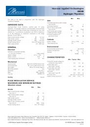
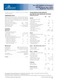
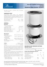
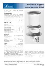
<strong>CX1140LD</strong><br />
<strong>Deuterium</strong> <strong>Thyratron</strong><br />
The data to be read in conjunction with the Hydrogen<br />
<strong>Thyratron</strong> Preamble.<br />
ABRIDGED DATA<br />
<strong>Deuterium</strong>-filled, fast recovery, tetrode thyratron, specifically<br />
designed for operation under medical linac conditions. A<br />
reservoir operating from the cathode heater supply is<br />
incorporated.<br />
Peak forward anode voltage . . . . . . 33 kV max<br />
Peak anode current . . . . . . . . 1000 A max<br />
Average anode current:<br />
continuous operation . . . . . . . . 1.25 A max<br />
intermittent operation . . . . . . . . 2.2 A max<br />
GENERAL<br />
Electrical<br />
Cathode (connected internally<br />
to mid-point of heater) . . . . . . . . oxide coated<br />
Heater voltage . . . . . . . . . 6.3 + 5% V<br />
Heater current . . . . . . . . . . . 22 A<br />
Tube heating time (minimum) . . . . . . . 5.0 min<br />
Mechanical<br />
Overall length . . . . . 317.5 mm (12.500 inches) max<br />
Overall diameter . . . . . 84.12 mm (3.312 inches) max<br />
Net weight . . . . . . . 0.7 kg (1 1 / 2 pounds) approx<br />
Mounting position (see note 1) . . . . . . . . . any<br />
Base . pin spacing as B5F; metal shell with micalex insert<br />
Top cap (see note 2) . . . . . . . . . BS448-CT3<br />
<strong>CX1140LD</strong> is also available with a flange base with flying leads<br />
as type CX1551L.<br />
Cooling . . . . . . . . . . . . . . . natural<br />
PULSE MODULATOR SERVICE<br />
MAXIMUM AND MINIMUM RATINGS<br />
(Absolute values)<br />
Min Max<br />
Anode<br />
Peak forward anode voltage<br />
(see note 3) . . . . . . . . . – 25 kV<br />
Peak inverse anode voltage (see note 4) . – 25 kV<br />
Peak anode current . . . . . . . – 1000 A<br />
Peak anode current (pulse repetition rate<br />
limited to 60 pps max) . . . . . . – 2000 A<br />
Average anode current:<br />
continuous operation . . . . . . – 1.25 A<br />
intermittent operation . . . . . . – 2.2 A<br />
Rate of rise of anode current<br />
(see note 5) . . . . . . . . . – 5000 A/ms<br />
Grid 2<br />
Unloaded grid 2 drive pulse voltage<br />
(see note 6) . . . . . . . . 300 1000 V<br />
Grid 2 pulse duration . . . . . . . 1.0 – ms<br />
Rate of rise of grid 2 pulse (see note 5) . 1.0 – kV/ms<br />
Grid 2 pulse delay . . . . . . . . 0.5 3.0 ms<br />
Peak inverse grid 2 voltage . . . . . – 450 V<br />
Loaded grid 2 bias voltage . . . . . 0 7150 V<br />
Grid 2 drive impedance . . . . . 50 500 O<br />
Grid 2 bias impedance . . . . . . 30 50 kO<br />
Grid 1 – DC Primed (See note 7)<br />
DC grid 1 unloaded priming voltage . 75 150 V<br />
DC grid 1 priming current . . . . 50 100 mA<br />
e2v technologies limited, Waterhouse Lane, Chelmsford, Essex CM1 2QU England Telephone: +44 (0)1245 493493 Facsimile: +44 (0)1245 492492<br />
e-mail: enquiries@e2vtechnologies.com Internet: www.e2vtechnologies.com Holding Company: e2v holdings limited<br />
e2v technologies inc. 4 Westchester Plaza, PO Box 1482, Elmsford, NY10523-1482 USA Telephone: (914) 592-6050 Facsimile: (914) 592-5148<br />
e-mail: enquiries@e2vtechnologies.us<br />
# e2v technologies limited 2003 A1A-<strong>CX1140LD</strong> Issue 1, July 2003<br />
282G/2069
MAXIMUM AND MINIMUM RATINGS<br />
(Continued)<br />
Min Max<br />
Grid 1 – Pulsed (see note 7)<br />
Unloaded grid 1 drive pulse voltage<br />
(see note 6) . . . . . . . . 300 1000 V<br />
Grid 1 pulse duration . . . . . . . 2.0 – ms<br />
Rate of rise of grid 1 pulse (see note 5) . 1.0 – kV/ms<br />
Peak inverse grid 1 voltage . . . . . – 450 V<br />
Loaded grid 1 bias voltage . . . . . . . . see note 8<br />
Peak grid 1 drive current . . . . . 0.3 1.0 A<br />
Cathode<br />
Heater voltage . . . . . . . . . 6.3 + 5% V<br />
Tube heating time . . . . . . . . 5.0 – min<br />
Environmental<br />
Ambient temperature . . . . . . 750 +90 8C<br />
Altitude . . . . . . . . . . . – 3 km<br />
– 10 000 ft<br />
CHARACTERISTICS<br />
Min Typical Max<br />
Critical DC anode voltage for<br />
conduction (see note 9) . . . – 0.5 2.0 kV<br />
Anode delay time<br />
(see notes 9 and 10) . . . . – 0.15 0.25 ms<br />
Anode delay time drift<br />
(see notes 9 and 11) . . . . – 20 50 ns<br />
Time jitter (see note 9) . . . . – 1.0 5.0 ns<br />
Recovery time . . . . . see note 12 and graph, page 3<br />
Heater current (at 6.3 V) . . 18 22 25 A<br />
RATINGS FOR FAULT CONDITIONS,<br />
SINGLE-SHOT OR CROWBAR SERVICE<br />
(See note 7)<br />
DC forward anode voltage . . . . . . 30 kV max<br />
Peak anode current . . . . . . . 10 000 A max<br />
Product of peak current and<br />
pulse duration . . . . . . . . . . 0.6 A.s max<br />
Repetition frequency . . . . . . . 1 pulse per 10 s max<br />
NOTES<br />
1. Clamping is only permissible by the base.<br />
2. A large area anode connector, e2v technologies type<br />
MA360, is recommended.<br />
3. The maximum permissible peak forward voltage for<br />
instantaneous starting is 33 kV and there must be no<br />
overshoot.<br />
4. The peak inverse voltage must not exceed 10 kV for the<br />
first 25 ms after the anode pulse.<br />
5. This rate of rise refers to that part of the leading edge of<br />
the pulse between 25% and 75% of the pulse amplitude.<br />
6. Measured with respect to cathode. In certain cases the<br />
maximum drive pulse voltage may be exceeded without<br />
damage to the tube; a maximum value of 2.5 kV is then<br />
recommended. When grid 1 is pulse driven, the last 0.25 ms<br />
of the top of the grid 1 pulse must overlap the<br />
corresponding first 0.25 ms of the top of the delayed grid 2<br />
pulse.<br />
7. DC priming is recommended for crowbar service. Grid 1<br />
pre-pulsing is recommended for operating conditions<br />
requiring minimum anode delay time drift and minimum<br />
jitter.<br />
8. DC negative bias voltages must not be applied to grid 1.<br />
When grid 1 is pulse driven, the potential of grid 1 may<br />
vary between 710 and +5 V with respect to cathode<br />
potential during the period between the completion of<br />
recovery and the commencement of the succeeding grid<br />
pulse.<br />
9. Typical figures are obtained on test using conditions of<br />
minimum grid drive (pre-pulse on grid 1).<br />
10. The time interval between the instant at which the rising<br />
unloaded grid 2 pulse reaches 25% of its pulse amplitude<br />
and the instant when anode conduction takes place.<br />
11. The drift in delay time over a period from 10 seconds to<br />
10 minutes after reaching full voltage.<br />
12. The recovery characteristics are controlled on a sampling<br />
basis.<br />
MA91 ADAPTOR ASSEMBLY<br />
In addition to standard top cap connectors and base sockets,<br />
adaptor assembly MA91 is available from e2v technologies. This<br />
is a five-contact socket fitted with flexible leads and terminal<br />
tags, and mounted on an insulating base plate. It provides a<br />
conversion from base to flange type mounting.<br />
<strong>CX1140LD</strong> is also available with a flange base with flying leads<br />
as type CX1551L.<br />
Further information is contained in the leaflet<br />
’Accessories for Hydrogen <strong>Thyratron</strong>s’.<br />
<strong>CX1140LD</strong>, page 2<br />
# e2v technologies
HEALTH AND SAFETY HAZARDS<br />
e2v technologies hydrogen thyratrons are safe to handle and<br />
operate, provided that the relevant precautions stated herein<br />
are observed. e2v technologies does not accept responsibility<br />
for damage or injury resulting from the use of electronic devices<br />
it produces. Equipment manufacturers and users must ensure<br />
that adequate precautions are taken. Appropriate warning<br />
labels and notices must be provided on equipments<br />
incorporating e2v technologies devices and in operating<br />
manuals.<br />
High Voltage<br />
Equipment must be designed so that personnel cannot come<br />
into contact with high voltage circuits. All high voltage circuits<br />
and terminals must be enclosed and fail-safe interlock switches<br />
must be fitted to disconnect the primary power supply and<br />
discharge all high voltage capacitors and other stored charges<br />
before allowing access. Interlock switches must not be<br />
bypassed to allow operation with access doors open.<br />
X-Ray Radiation<br />
All high voltage devices produce X-rays during operation and<br />
may require shielding. The X-ray radiation from hydrogen<br />
thyratrons is usually reduced to a safe level by enclosing the<br />
equipment or shielding the thyratron with at least 1.6 mm<br />
( 1 / 16 inch) thick steel panels.<br />
Users and equipment manufacturers must check the radiation<br />
level under their maximum operating conditions.<br />
MAXIMUM RECOVERY CHARACTERISTICS<br />
15<br />
8198<br />
PEAK ANODE CURRENT 1000 A<br />
RE-APPLIED ANODE VOLTAGE 1 kV<br />
12.5<br />
GRID 2 VOLTAGE 0 V<br />
10<br />
712.5<br />
725<br />
MAXIMUM RECOVERY TIME (ms)<br />
7.5<br />
7100<br />
5<br />
2.5<br />
0 100 500 1000 5000 10 000 50 000<br />
GRID 2 RECOVERY IMPEDANCE (O)<br />
# e2v technologies <strong>CX1140LD</strong>, page 3
OUTLINE<br />
(All dimensions without limits are nominal)<br />
Ref Millimetres Inches<br />
2871C<br />
D<br />
1E<br />
A 304.8 + 12.7 12.000 + 0.500<br />
B 84.12 max 3.312 max<br />
C 215.9 + 12.7 8.500 + 0.500<br />
D 12.7 min 0.500 min<br />
E 14.38 + 0.18 0.566 + 0.007<br />
F 4.750 + 0.076 0.187 + 0.003<br />
G 31.75 1.250<br />
H 49.2 1.937<br />
J 77.77 + 1.57 3.062 + 0.062<br />
K 19.56 max 0.770 max<br />
L 1.85 max 0.073 max<br />
M 14.6 min 0.575 min<br />
N 6.6 max 0.260 max<br />
Inch dimensions have been derived from millimetres.<br />
A<br />
C<br />
1B<br />
BASE PIN SPACING<br />
AS B5F. METAL SHELL<br />
WITH MICALEX INSERT<br />
4316A<br />
g 2<br />
3<br />
a<br />
Cap<br />
1J<br />
H<br />
k, h ct 2 4<br />
g 1<br />
K<br />
M<br />
1N<br />
L<br />
1<br />
h k<br />
Reservoirs<br />
(internal)<br />
5<br />
h k<br />
5 PINS 1F<br />
ON G PCD<br />
3<br />
4<br />
2<br />
5<br />
1<br />
308<br />
308<br />
Pin<br />
Element<br />
1 Heater<br />
2 Cathode, connected internally<br />
to heater mid-point<br />
3 Grid 2<br />
4 Grid 1<br />
5 Heater<br />
Top cap Anode<br />
Whilst e2v technologies has taken care to ensure the accuracy of the information contained herein it accepts no responsibility for the consequences of any use<br />
thereof and also reserves the right to change the specification of goods without notice. e2v technologies accepts no liability beyond that set out in its standard<br />
conditions of sale in respect of infringement of third party patents arising from the use of tubes or other devices in accordance with information contained herein.<br />
<strong>CX1140LD</strong>, page 4<br />
Printed in England<br />
# e2v technologies