T361_prospect.pdf (ENG) - Iskraemeco
T361_prospect.pdf (ENG) - Iskraemeco
T361_prospect.pdf (ENG) - Iskraemeco

Create successful ePaper yourself
Turn your PDF publications into a flip-book with our unique Google optimized e-Paper software.
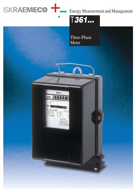
Energy Measurement and Management<br />
<strong>T361</strong>...<br />
Three-Phase<br />
Meter
<strong>T361</strong>...<br />
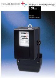
APPLICATION<br />
The electricity meter type <strong>T361</strong>.. is suitable for measuring active<br />
energy for direct connection in three-phase three- or four-wire networks<br />
at balanced or nonbalanced load.<br />
RATINGS<br />
The measuring and technical characteristics comply with<br />
IEC 62053-11, IEC 62052-11, IEC 60521, BS 5685 specifications.<br />
The accuracy class is 2.<br />
DESIGN<br />
The following versions of meters are manufactured:<br />
Type <strong>T361</strong>C for 400 % current loading<br />
Type <strong>T361</strong>E for 500 % current loading<br />
Type <strong>T361</strong>F for 600 % current loading<br />
Additional marking designates as follows:<br />
D: double tariff type meter (<strong>T361</strong>ED ..)<br />
2: meter with magnetic bearing (<strong>T361</strong>E2 ..)<br />
S: technological changes on th emeters that are tied with year 2002<br />
2<br />
CONSTRUCTION<br />
Meter Base with Terminals<br />
Meter base is made of bakelite, highly resistant to creep current. A<br />
suspension hook is fastened to it. It allows different affixing dimensions<br />
of the meter with a screw outside the case or under it. The<br />
<strong>T361</strong>..meter base makes an integral part with the terminal block,<br />
made in accordance with BS 5685 Standard. The flashover and<br />
creep distances in the bakelite framework, between metal parts of<br />
individual circuits on one hand, and terminals and outside contact<br />
parts on the other, are large enough to assure high breakdown<br />
strength.<br />
Fixing of outer wire is provided by means of two M6 screws. Diameter<br />
of terminal hole is max. 12.5 mm.<br />
One auxiliary terminal is available only for double tariff veision.<br />
Meter Cover<br />
Meter cover is made of bakelite or transparent thermoplastic material.<br />
Bakelite cover has a glass window at the front side. The window is<br />
sealed with silicon sealant from the internal side and is fastened with<br />
selflocking elastic washers. The cover is fastened to the base with two<br />
sealing screws so that better sealing between the cover and the base<br />
is attained. During the calibration the covers can be hanged on the<br />
meter base without screwing.<br />
Transparent cover is made of thermoplastic material (Polymethile-<br />
Methacrilate or Polycarbonate), resistant to shocks, and strengthened<br />
with ribs on the inner side. The cover is fastened to the base with two<br />
sealing screws, so that sealing is possible irrespective of the position<br />
of the terminal block cover.<br />
In the cover rabbet there is a solid rubber gasket meeting all dustproof<br />
requirements, and enabling the cover to be smoothly placed<br />
on the base.<br />
During the calibration the cover can be hanged on the meter base.<br />
Terminal Block Cover<br />
Terminal block cover is made of solid, self-extinguishable, thermoplastic<br />
or duroplastic material. It can be supplied in short, extended<br />
or middle version. The terminal block cover prevents undesired<br />
access to the suspension hook and terminals.<br />
3<br />
5<br />
6<br />
4<br />
7<br />
8<br />
1<br />
SETTING ELEMENTS<br />
1 – sensitivity adjustment<br />
2 – coarse adjustment of number of revolutions<br />
3 – fine adjustment of number of revolutions<br />
4 – adjustment of small loads<br />
5 – coarse phase adjustment<br />
6 – fine phase adjustment<br />
7 – balance of torques of driving elements<br />
8 – reverse phase sequence adjustment
<strong>T361</strong>...<br />
Electromagnets<br />
The type <strong>T361</strong>.. meter employs<br />
three similar electromagnet elements<br />
which are mounted on a<br />
robust die-cast frame. Two elements<br />
drive the lower disc and<br />
one the upper disc on which the<br />
brake magnet operates.<br />
The voltage electromagnet of<br />
each element has a double<br />
magnetic circuit and the current<br />
electromagnet is of U form.<br />
Electromagnetic sheet of a corresponding<br />
initial permeability in<br />
current cores assures specified<br />
error curves with respect to the<br />
load, either at small loads or<br />
overloads.<br />
Frame<br />
For the drive systems and the<br />
brake system a pressure-injected<br />
SiAl casting of high physical<br />
strength and endurance is<br />
applied. The framework is fastened<br />
with two screws to the<br />
base through an adapter which<br />
unloads the bakelite base, and<br />
makes the measuring system<br />
elastic.<br />
Brake Magnet<br />
It effects on the upper disc of<br />
the rotor. A massive, two-directional<br />
brake magnet is made of<br />
AlNiCo alloy, and sealed in a<br />
SiAl casting. The number of revolutions<br />
can be precisely set by<br />
adjusting screws placed outside<br />
the magnet. However, by turning<br />
the complete brake system, revolutions<br />
can be set approximately.<br />
Between the poles of both<br />
magnets there is a temperature<br />
compensative material compensating<br />
registration changes in<br />
respect of temperature variations<br />
in a wide temperature range.<br />
Rotor<br />
The two-disc rotor are made<br />
from aluminium sheet selected<br />
for its conductivity and purity.<br />
It is free from particles of ferrous<br />
metal. The upper disc has a<br />
mark which helps count the revolutions<br />
on the disc for testing<br />
purposes. On special request it<br />
can also be marked by a 100-,<br />
200-, 400-division pattern for<br />
stroboscopic testing.<br />
The Lower Bearing<br />
It is of two-cup or magnetic type.<br />
The two-cup bearing<br />
Between two sapphire cups lies<br />
a polished steel ball, protected<br />
against corrosion by a thin layer<br />
of good quality oil. Initial friction<br />
is insignificant, and the bearing<br />
has a long life. The bearing<br />
assembly is fastened with spring<br />
to prevent damage during<br />
transportation, and to enable a<br />
simple exchange of the rotor by<br />
pushing the bearing assembly<br />
only, without any readjustment.<br />
TECHNICAL DATA<br />
Type <strong>T361</strong>F <strong>T361</strong>L <strong>T361</strong>C <strong>T361</strong>B <strong>T361</strong>E <strong>T361</strong>E <strong>T361</strong>F <strong>T361</strong>C<br />
Ref. voltage Ur (V) 3 x 230/400<br />
Ref. frequency (Hz) 50<br />
Basic current Ib (A) 10 10 20 30 20 40 20 40<br />
Max. current Imax (A) 40 60 80 90 100 100 120 160<br />
Thermal current (A) 48 72 96 108 120 120 144 192<br />
Losses in voltage coils (W) 3 x 1 to 1.1<br />
at the rated voltage (VA) 3 x 4.6 to 4.9<br />
Losses in current coils (W) 3 x 0.10 3 x 0.10 3 x 0.28 3 x 0.50 3 x 0.23 3 x 0.65 3 x 0.23 3 x 0.53<br />
at the basic current (VA) 3 x 0.12 3 x 0.12 3 x 0.32 3 x 0.55 3 x 0.25 3 x 0.8 3 x 0.25 3 x 0.6<br />
Torque at basic load (x10 -4 Nm) 6.5 6.7 10.1 14.2 9.8 20 7.6 12<br />
Meter constant (revs/kWh) 120 75 48 48 37.5 37.5 37.5 24<br />
Rated number of<br />
revolutions at basic load (r.p.m.) 13.8 8.625 11.04 16.56 8.625 17.25 8.625 11.04<br />
No-load running<br />
Rotor does not run when the current circuit is open, and if the voltage varies from 80% to 110% Uref.<br />
Starting current at U.P.f<br />
< 0.5 % Ib<br />
Dielectric strength<br />
Between the parts at load and inner meter’s metal parts: 2000Vef.<br />
Between the parts at load and outer touching metal parts: 4000Vef.<br />
Surge voltage strength (1.2/50 µs)<br />
7 kV (up to 12 kV on special request)<br />
Weight of the rotor (g) approx. 52 with two-cup bearing, and 55 with magnetic bearing<br />
Weight of the meter (kg) approx. 3.2 to 3.5<br />
Other rated voltages up to 500 V and currents (5/20, 10/20, 5/30, 10/30, 5/40, 15/60, 20/60, 10/80, 50/100, 30/120, 80/160 A, ...) are also available on special request.
<strong>T361</strong>...<br />
The magnetic bearing<br />
The temperature compensated<br />
magnetic bearing has two<br />
magnetic parts with equaly<br />
polarised adjacent surfaces. Due<br />
to the mutually repelling forces<br />
between the two magnetic<br />
surfaces and the rotor weight, the<br />
rotor magnet floats at a distance<br />
from the stator magnet.<br />
The rotor is guided by a highly<br />
polished spindle which projects<br />
from the lower part of the bearing<br />
into the upper part, its upper<br />
pin acting as an armature. The<br />
stainless steel spindle runs in a<br />
graphite bearing sleeve, making<br />
lubrication unnecessary.<br />
The Upper Bearing<br />
It is pin-like acting as an armature.<br />
The polished stainless steel<br />
spindle runs in the upper bearing,<br />
which is together with the<br />
worm made of solid thermoplastic<br />
material. No lubrication is<br />
necessary.<br />
The Register<br />
Single- rate register consists of<br />
six or seven graduated drums.<br />
The periphery of the last drum is<br />
divided in 100 sections. Thin<br />
polished axles are rotating in<br />
plastic bearings causing<br />
minimum friction and high error<br />
stability at small loads. No<br />
lubrication of bearings is<br />
necessary. The register<br />
framework can be fastened to the<br />
meter framework with one screw<br />
without an adjustment plate, so<br />
that the worm and the worm<br />
wheel fit each other completely.<br />
Two versions of single-tariff register<br />
are produced: a register<br />
with standard digit drum with the<br />
size of numbers 4,7 x 2,3 mm<br />
and a register with larger digit<br />
drum with size of numbers 6,9 x<br />
3,65 mm.<br />
Two- rate register has six or<br />
seven digits for each tariff. The<br />
rear register circumference is<br />
divided in 100 sections. The tariff<br />
switchover is enabled by a<br />
change-over relay functioning via<br />
differential gear. Thus the register<br />
display error at switchover from<br />
the first to the second tariff and<br />
vice-versa is eliminated. The<br />
change-over relay is a D.C.<br />
version supplied via the<br />
incorporated rectifier and<br />
protective resistor.<br />
Adjustment Devices<br />
Adjustment devices are placed<br />
at the outside of individual driving<br />
systems. They are easily<br />
accessible, the setting range is<br />
wide enough, their interaction is<br />
minimal. Adjustment is partially<br />
manual, and partialy done with a<br />
screw-driver.<br />
Meter connection<br />
Normal or reverse phase<br />
sequence connection to the<br />
meter does not effect no-load<br />
running between 80% to 110 %<br />
reference voltage.<br />
TYPICAL PERFORMANCE CHARACTERISTIC<br />
Load curves<br />
+4<br />
+2<br />
F %<br />
-2<br />
-4<br />
+4<br />
+2<br />
F %<br />
-2<br />
-4<br />
+4<br />
+2<br />
F %<br />
-2<br />
-4<br />
+4<br />
+2<br />
F %<br />
-2<br />
-4<br />
Balanced load<br />
T36C (400% Ib)<br />
Single phase load<br />
Balanced load<br />
P.F. = 1<br />
L.F. = 0.5<br />
<strong>T361</strong>E,<strong>T361</strong>F (500,600% Ib)<br />
Single phase load<br />
5 20 100 200 300 400 500 600 Ib %<br />
10<br />
Error due to temperature variation<br />
+2<br />
+1<br />
F %<br />
-1<br />
-2<br />
-40<br />
-30<br />
-20 -10 0 +10 +20 +30 +40 +50 +60 °C
<strong>T361</strong>...<br />
CONNECTION DIAGRAMS<br />
4000<br />
4101<br />
Z<br />
1<br />
L1<br />
L2<br />
L3<br />
N<br />
3 4 6 7 9 10 12<br />
1 2 3 4<br />
L1<br />
L2<br />
6 7 9 10 11 12 13<br />
ASSEMBLING DATA FOR METER<br />
144<br />
Ø 8.0 (9.5, 12.5)<br />
6.25<br />
6.5<br />
1.5<br />
134<br />
30<br />
a<br />
204<br />
94<br />
12 14<br />
7 x 17.5 = 122.5<br />
b<br />
68<br />
145<br />
40<br />
178<br />
42.5<br />
a= 230 ±1 mm external hanging<br />
180 ±1 mm internal hanging (suspension hook hidden behind the meter base)<br />
b= 28 ±1 mm short terminal cover<br />
59 ±1 mm medium terminal cover<br />
102 ±1 mm extended terminal cover
<strong>T361</strong>...<br />
Order specifications<br />
1. Meter type: . . . . . . . . . . . . . . . . . . . . . . . . . . . . . . . . . . . . . . . . . . . .<br />
2. Rated voltage and frequency: . . . . . . . . . . . . . . . . . . . . . . . . . . . . .<br />
3. Basic and maximum current: . . . . . . . . . . . . . . . . . . . . . . . . . . . . . .<br />
4. Six- or seven- drum register (for single-tariff register<br />
specify the size of numbers) . . . . . . . . . . . . . . . . . . . . . . . . . . . . . .<br />
5. Connection: . . . . . . . . . . . . . . . . . . . . . . . . . . . . . . . . . . . . . . . . . . . .<br />
6. Lower bearing version . . . . . . . . . . . . . . . . . . . . . . . . . . . . . . . . . . .<br />
7. Nameplate: owner‘s information . . . . . . . . . . . . . . . . . . . . . . . . . . . .<br />
8. Size of terminal block cover . . . . . . . . . . . . . . . . . . . . . . . . . . . . . . .<br />
9. Packaging . . . . . . . . . . . . . . . . . . . . . . . . . . . . . . . . . . . . . . . . . . . . .<br />
Example<br />
<strong>T361</strong>C2 – 1000 pcs.<br />
3 x 230/400 V, 50 Hz<br />
40 – 160 A<br />
single-tariff, seven-digit register with larger digit drums<br />
4000<br />
magnetic bearing<br />
The Property of...<br />
extended thermoplastic<br />
container (boxes, truck)<br />
Packaging<br />
The meters are supplied individually or in groups in boxes.<br />
Data on dimensions and gross weight depend on packaging:<br />
Packaging No. of packed External dimensions Gross weight<br />
meters of packages (mm) approx. kg<br />
individual 1 282 x 182 x 142 3.5<br />
truck 50 1200 x 800 x 790 200<br />
80 1200 x 800 x 1005 310<br />
container 66 1075 x 625 x 1080 254<br />
wooden box 80 1276 x 872 x 1028 330<br />
Packaging depends on destination, type of transport and specific<br />
requirements of individual buyers.<br />
Owing to periodical improvements of our products the supplied products can differ in some details<br />
from data stated in the <strong>prospect</strong>us material<br />
9610/39<br />
<strong>Iskraemeco</strong>, Energy Measurement and Management<br />
4000 Kranj, Savska loka 4, Slovenia<br />
Telephone: (+386 64) 26 40, Telefax: (+386 64) 26 43 76,<br />
http://www.iskraemeco.si, e-mail: info@iskraemeco.si<br />
Published by <strong>Iskraemeco</strong>. Data subject to alteration without notice.