QDK PIC24/dsPIC-XC16 - Quantum Leaps
QDK PIC24/dsPIC-XC16 - Quantum Leaps
QDK PIC24/dsPIC-XC16 - Quantum Leaps

Create successful ePaper yourself
Turn your PDF publications into a flip-book with our unique Google optimized e-Paper software.
<strong>QDK</strong><br />
<strong>PIC24</strong>/<strong>dsPIC</strong>-<strong>XC16</strong><br />
www.state-machine.com/pic<br />
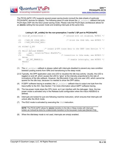
The <strong>PIC24</strong>-<strong>dsPIC</strong> CPU supports several power-saving levels (consult the data sheets of particular<br />
<strong>PIC24</strong>/<strong>dsPIC</strong> devices for details). The following piece of code shows the QF_onIdle() callback that puts<br />
Pic24-dspic DSP into the IDLE power-saving mode. Please note that Pic24-dspic architecture allows for<br />
an atomic setting the low-power mode and enabling interrupts at the same time.<br />
Listing 6: QF_onIdle() for the non-preemptive (“vanilla”) QP port to <strong>PIC24</strong>/<strong>dsPIC</strong><br />
(1) void QF_onIdle(void) { /* entered with int disabled, NOTE01 */<br />
(2) //LED_ON (IDLE_LED); /* blink the IDLE LED, see NOTE02 */<br />
(3) //LED_OFF(IDLE_LED);<br />
(4) #ifdef Q_SPY<br />
. . . /* output Q-SPY trace data to the UART (see Section 7) */<br />
(5) #elif defined NDEBUG<br />
(6) __asm__ volatile("disi #0x0001");<br />
(7) Idle(); /* transition to Idle mode, see NOTE03 */<br />
#else<br />
(8) QF_INT_ENABLE(); /* enable interrupts, see NOTE01 */<br />
#endif<br />
}<br />
(1) The QF_onIdle() callback is always called with interrupts disabled to prevent any race condition<br />
between posting events from ISRs and transitioning to the sleep mode.<br />
(2-3) Typically, the DPP application uses one LED to visualize the idle loop activity. Usually, the LED is<br />
toggled on and off, which causes the LED to “glow” at the intensity proportional to the rate of<br />
invocations of the idle callback. However, the Microstick II has only one user LED, which cannot be<br />
spared for the idle loop, because it is needed to show the DPP status.<br />
(4) If QSPY software tracing is enabled, the QF_onIdle() callback tries to output one byte from the<br />
trace buffer to the SCI. See Section 7 for more information about QSPY software tracing.<br />
(5) The low-power mode stops the CPU clock, so it can interfere with the debugger. Here, the lowpower<br />
mode is activated only in the Release build configuration when the macro NDEBUG is<br />
defined.<br />
(6) Interrupts are locked for just one following machine instruction, which ensures that interrupts will<br />
unlock after the IDLE mode.<br />
(7) The IDLE mode is activated by executing the IDLE instruction.<br />
NOTE: The <strong>PIC24</strong>-<strong>dsPIC</strong> allows for atomic transition to the Idle or Sleep modes with interrupts<br />
locked, as it should be done for a deterministic transition to the low-power mode (see [Samek 07a]).<br />
(8) When the idle/sleep mode is not used, interrupts are simply enabled.<br />
Copyright © <strong>Quantum</strong> <strong>Leaps</strong>, LLC. All Rights Reserved.<br />
16 of 35