QDK PIC24/dsPIC-XC16 - Quantum Leaps
QDK PIC24/dsPIC-XC16 - Quantum Leaps
QDK PIC24/dsPIC-XC16 - Quantum Leaps

Create successful ePaper yourself
Turn your PDF publications into a flip-book with our unique Google optimized e-Paper software.
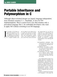
QP state machine frameworks for <strong>PIC24</strong>/<strong>dsPIC</strong><br />
<strong>QDK</strong><br />
<strong>PIC24</strong>/<strong>dsPIC</strong>-<strong>XC16</strong><br />
Document Revision E<br />
February 2013
Table of Contents<br />
1 Introduction ..................................................................................................................................................... 1<br />
1.1 About QP ............................................................................................................................................... 2<br />
1.2 About QM .............................................................................................................................................. 3<br />
1.3 About this <strong>QDK</strong> ......................................................................................................................................... 3<br />
1.4 About the QP Port to <strong>PIC24</strong>/<strong>dsPIC</strong> ........................................................................................................ 4<br />
1.5 What’s Included in the <strong>QDK</strong>-<strong>PIC24</strong>-<strong>dsPIC</strong> .............................................................................................. 5<br />
1.6 Licensing QP ......................................................................................................................................... 5<br />
1.7 Licensing QM ........................................................................................................................................ 5<br />
2 Getting Started ................................................................................................................................................ 6<br />
2.1 Building the QP Libraries .......................................................................................................................... 8<br />
2.2 Building and Running the Examples ......................................................................................................... 9<br />
2.2.1 Building the Example Projects in the MPLABX IDE ........................................................................ 9<br />
2.2.2 Programming the Example to Run under the MPLAB Debugger ................................................... 9<br />
2.2.3 Collecting the QS software trace .................................................................................................... 10<br />
3 Cooperative “Vanilla” Port ............................................................................................................................. 12<br />
3.1 The qep_port.h Header File ...................................................................................................................... 12<br />
3.2 The qf_port.h Header File ......................................................................................................................... 12<br />
3.3 ISRs in the Non-Preemptive “Vanilla” Configuration ................................................................................. 14<br />
3.3.1 PSV Usage in ISRs ....................................................................................................................... 15<br />
3.3.2 Shadow Registers Usage in ISRs ................................................................................................. 15<br />
3.3.3 Assigning/Changing Interrupt Priorities in Software ....................................................................... 15<br />
3.4 QP Idle Loop Customization in QF_onIdle() .............................................................................................. 15<br />
4 Preemptive Configuration with QK ................................................................................................................ 17<br />
4.1 QK-specific ISR Entry and Exit Macros (file qk_port.h) ............................................................................. 17<br />
4.2 ISRs with the Preemptive QK Kernel ........................................................................................................ 19<br />
4.2.1 Explanation of ISR code for the preemptive QK kernel ................................................................. 20<br />
4.3 Idle Loop Customization in the QK Port .................................................................................................... 22<br />
4.4 Testing QK Preemption Scenarios ............................................................................................................ 23<br />
4.4.1 Interrupt Nesting Test ..................................................................................................................... 24<br />
4.4.2 Task Preemption Test .................................................................................................................... 24<br />
4.4.3 Other Tests .................................................................................................................................... 25<br />
5 Implementing “Zero Interrupt Latency” with the NMI .................................................................................. 26<br />
5.1 Communication between NMIs and QP .................................................................................................... 26<br />
5.2 Implementation Considerations for the NMIs ............................................................................................ 26<br />
6 BSP for the Microstick II Board ...................................................................................................................... 27<br />
6.1 Setting the Sizes of Stack and Heap ......................................................................................................... 27<br />
6.2 The BSP header file bsp.h ........................................................................................................................ 28<br />
6.3 BSP initialization ....................................................................................................................................... 28<br />
6.4 Starting Interrupts in QF_onStartup() ........................................................................................................ 28<br />
6.5 Assertion Handling Policy in Q_onAssert() ............................................................................................... 29<br />
7 The QS Software Tracing Instrumentation ................................................................................................... 30<br />
7.1 QS Time Stamp Callback QS_onGetTime() .............................................................................................. 31<br />
7.2 QS Trace Output in QF_onIdle()/QK_onIdle() ........................................................................................... 33<br />
7.3 Invoking the QSpy Host Application .......................................................................................................... 33<br />
8 Related Documents and References ............................................................................................................. 34<br />
9 Contact Information ........................................................................................................................................ 35<br />
Copyright © <strong>Quantum</strong> <strong>Leaps</strong>, LLC. All Rights Reserved.<br />
i
1 Introduction<br />
This QP Development Kit (<strong>QDK</strong>) describes how to use the QP/C state machine framework with the<br />
Microchip <strong>PIC24</strong>/<strong>dsPIC</strong> MCUs/DSCs and the Microchip MPLABX IDE and the <strong>XC16</strong> compiler. The actual<br />
hardware/software used to test this <strong>QDK</strong> as shown in Figure 1 and described below:<br />
Figure 1: Microstick II board with TTL-RS232 transceiver<br />
Microstick II<br />
board with<br />
PKOB debugger<br />
User LED<br />
USB to PC<br />
(power + debugging)<br />
<strong>PIC24</strong>/<strong>dsPIC</strong><br />
device<br />
QS data<br />
to host PC<br />
TTL to RS232<br />
transceiver board<br />
The actual hardware/software used to test this <strong>QDK</strong> is described below (see Figure 1):<br />
1. Microchip Microstick II board [Microstick2] with <strong>PIC24</strong>FJ64GB002 or <strong>dsPIC</strong>33FJ128MC devices<br />
2. Microchip MPLABX® IDE v1.41 and <strong>XC16</strong> compiler v1.10<br />
3. QP/C 4.5.04 or higher<br />
Copyright © <strong>Quantum</strong> <strong>Leaps</strong>, LLC. All Rights Reserved.<br />
1 of 35
<strong>QDK</strong><br />
<strong>PIC24</strong>/<strong>dsPIC</strong>-<strong>XC16</strong><br />
www.state-machine.com/pic<br />
NOTE: For the QS (Q-SPY) software tracing output, you also need a<br />
TTL-to-RS-232 transceiver board. Such boards are available from a<br />
number of vendors. For example Figure 1 shows the RS232 to TTL<br />
converter board 3.3V to 5V from NKC Electronics ($9.99<br />
http://www.nkcelectronics.com/rs232-to-ttl-converter-board-<br />
33v232335.html).<br />
1.1 About QP<br />
QP is a family of very lightweight, open source, state machine frameworks<br />
for developing event-driven applications. QP enables building well-structured<br />
embedded applications as a set of concurrently executing hierarchical state<br />
machines (UML statecharts) directly in C or C++. QP is described in great<br />
detail in the book “Practical UML Statecharts in C/C++, Second Edition:<br />
Event-Driven Programming for Embedded Systems” [PSiCC2] (Newnes,<br />
2008).<br />
As shown in Figure 2, QP consists of a universal UML-compliant event<br />
processor (QEP), a portable real-time framework (QF), a tiny preemptive<br />
kernel (QK), and software tracing instrumentation (QS). Current versions of<br />
QP include: QP/C and QP/C++, which require about 4KB of code and a<br />
few hundred bytes of RAM, and the ultra-lightweight QP-nano, which requires<br />
only 1-2KB of code and just several bytes of RAM. QP can work with or without a traditional RTOS or OS.<br />
In the simplest configuration, QP can completely replace a traditional RTOS. QP can manage up to 63<br />
concurrently executing tasks structured as state machines (called active objects in UML).<br />
QP can work with or without a traditional RTOS or OS. In the simplest configuration, QP can completely<br />
replace a traditional RTOS. QP can manage up to 63 concurrently executing tasks structured as state<br />
machines (called active objects in UML).<br />
Figure 2: QP components and their relationship with the target hardware, board support package<br />
(BSP), and the application comprised of state machines<br />
Copyright © <strong>Quantum</strong> <strong>Leaps</strong>, LLC. All Rights Reserved.<br />
2 of 35
<strong>QDK</strong><br />
<strong>PIC24</strong>/<strong>dsPIC</strong>-<strong>XC16</strong><br />
www.state-machine.com/pic<br />
1.2 About QM<br />
QM (QP Modeler) is a free, cross-platform, graphical UML modeling tool for<br />
designing and implementing real-time embedded applications based on the<br />
QP state machine frameworks. QM is available for Windows, Linux, and<br />
Mac OS X. QM provides intuitive diagramming environment for creating good<br />
looking hierarchical state machine diagrams and hierarchical outline of your<br />
entire application. QM eliminates coding errors by automatic generation of<br />
compact C or C++ code that is 100% traceable from your design. Please visit<br />
state-machine.com/qm for more information about QM.<br />
1.3 About this <strong>QDK</strong><br />
This <strong>QDK</strong> provides working examples of code running under both the cooperative Vanilla kernel and the<br />
preemptive QK kernel. The example code is based on the Dining Philosopher Problem (DPP) sample<br />
application described in Chapter 7 of [PSiCC2] as well as in the Application Note “Dining Philosopher<br />
Problem” [QL AN-DPP 08] (included in the example code distribution).<br />
The entire source code included with this <strong>QDK</strong> can be edited manually in a traditional code editor.<br />
However, significant parts of the code have been generated automatically by the QM modeling tool<br />
from the dpp.qm model file included in the <strong>QDK</strong>. The preferred way of developing QP applications is to<br />
make all the changes in the model and generate the code automatically.<br />
Figure 3: The example model opened in the QM modeling tool<br />
NOTE: The significant parts of the source code (files dpp.h, philo.c, and table.c) have been<br />
generated by the QM modeling tool from the dpp.qm model, which is the same for the Vanilla and<br />
QK versions of the DPP application. These files can be edited by hand (after unchecking the readonly<br />
property), but the changes made at the code level won't be incorporated back into the model.<br />
Copyright © <strong>Quantum</strong> <strong>Leaps</strong>, LLC. All Rights Reserved.<br />
3 of 35
<strong>QDK</strong><br />
<strong>PIC24</strong>/<strong>dsPIC</strong>-<strong>XC16</strong><br />
www.state-machine.com/pic<br />
1.4 About the QP Port to <strong>PIC24</strong>/<strong>dsPIC</strong><br />
Figure 4 shows the architecture of the QP port to <strong>PIC24</strong>/<strong>dsPIC</strong>. The port takes advantage of the<br />
<strong>PIC24</strong>/<strong>dsPIC</strong> interrupt priority level (IPL) management hardware. In both cooperative and preemptive QP<br />
ports the hardware priority levels are allocated as follows:<br />
1. All QP tasks (active objects) as well as the QP idle loop execute at the lowest IPL of zero.<br />
2. IPL levels 1 through 6 are used for maskable interrupts. These maskable interrupts (IPL 1..6) can call<br />
QP services, such as QF_tick(), QActive_postFIFO(), QF_publish(), and Q_NEW(). The<br />
maskable interrupts can nest on each other, which is the default in <strong>PIC24</strong>/<strong>dsPIC</strong>.<br />
3. This QP port never disables the IPL level 7, which is the Non-Maskable Interrupt (NMI) level. The<br />
NMI-level interrupt(s) cannot call any QP services. But the NMI can trigger a maskable interrupt, as<br />
shown by the dashed arrow in Figure 4. This triggered interrupt of IPL 1..6 can call QP services for<br />
signaling the QP tasks (active objects).<br />
Figure 4: Architecture of the <strong>PIC24</strong>/<strong>dsPIC</strong> port<br />
(IPL = 7) Non-Maskable Interrupt (NMI)<br />
IPL Level 7<br />
(NMI level)<br />
(IPL = 6) User interrupt<br />
(IPL = 5) User interrupt<br />
(IPL = 4) User interrupt<br />
IPL Levels 1-6<br />
(interrupt level)<br />
(IPL = 3) User interrupt<br />
(IPL = 2) User interrupt<br />
(IPL = 1) User interrupt<br />
(QP prio = n) User task (active object)<br />
(QP prio = n-1) User task (active object)<br />
. . .<br />
(QP prio = 2) User task (active object)<br />
IPL Level 0<br />
(task level)<br />
(QP prio = 1) User task (active object)<br />
(QP prio = 0) Idle task<br />
This layered software architecture fits very naturally with the <strong>PIC24</strong>/<strong>dsPIC</strong> hardware. The QP ports (both<br />
cooperative and preemptive) allow nesting of interrupts, which is the default in <strong>PIC24</strong>/<strong>dsPIC</strong>. Both<br />
cooperative and preemptive QP ports can work with the interrupt service routines (ISRs) generated by the<br />
Copyright © <strong>Quantum</strong> <strong>Leaps</strong>, LLC. All Rights Reserved.<br />
4 of 35
<strong>QDK</strong><br />
<strong>PIC24</strong>/<strong>dsPIC</strong>-<strong>XC16</strong><br />
www.state-machine.com/pic<br />
XC18 compiler, although the preemptive version requires special macros to be invoked upon entering and<br />
exiting ISRs.<br />
The interrupt locking policy is implemented very efficiently by means of the DISI instruction (see<br />
Section 3.2). As described in Section 8.2.3 of “<strong>PIC24</strong>F Family Reference Manual” [<strong>PIC24</strong> Ref], “The DISI<br />
instruction only disables interrupts with priority levels 1-6. Priority level 7 interrupts and all trap events still<br />
have the ability to interrupt the CPU when the DISI instruction is active.” This means that interrupts with<br />
IPL of 7 are never disabled and thus run with “zero interrupt latency”.<br />
NOTE: Obviously, true “zero interrupt latency” is technically impossible. The term means here that<br />
the NMI-level interrupt(s) execute with the minimal latency achievable in <strong>PIC24</strong>/<strong>dsPIC</strong> hardware and<br />
that no additional latency is added to the NMI-level interrupt(s) because of interrupt locking in QP.<br />
The use of NMI to achieve “zero interrupt latency” is explained in Section 5.<br />
1.5 What’s Included in the <strong>QDK</strong>-<strong>PIC24</strong>-<strong>dsPIC</strong><br />
This <strong>QDK</strong> provides the QP port for <strong>PIC24</strong> and <strong>dsPIC</strong> MCUs and two versions of the Dining Philosopher<br />
Problem (DPP) example for each processor (with the cooperative “vanilla” kernel and the preemptive QK<br />
kernel). The actual devices used for testing were: <strong>PIC24</strong>FJ64GB002 (<strong>PIC24</strong>) and <strong>dsPIC</strong>33FJ128MC<br />
(<strong>dsPIC</strong>).<br />
1.6 Licensing QP<br />
The Generally Available (GA) distribution of QP available for download from the www.statemachine.com/downloads<br />
website is offered with the following two licensing options:<br />
<br />
<br />
The GNU General Public License version 2 (GPL) as published by the Free<br />
Software Foundation and appearing in the file GPL.TXT included in the packaging of<br />
every <strong>Quantum</strong> <strong>Leaps</strong> software distribution. The GPL open source license allows<br />
you to use the software at no charge under the condition that if you redistribute the<br />
original software or applications derived from it, the complete source code for your<br />
application must be also available under the conditions of the GPL (GPL Section<br />
2[b]).<br />
One of several <strong>Quantum</strong> <strong>Leaps</strong> commercial licenses, which are designed for<br />
customers who wish to retain the proprietary status of their code and therefore cannot<br />
use the GNU General Public License. The customers who license <strong>Quantum</strong> <strong>Leaps</strong><br />
software under the commercial licenses do not use the software under the GPL and<br />
therefore are not subject to any of its terms.<br />
For more information, please visit the licensing section of our website at: www.statemachine.com/licensing.<br />
1.7 Licensing QM<br />
The QM graphical modeling tool available for download from the www.statemachine.com/downloads<br />
website is free to use, but is not open source. During the<br />
installation you will need to accept a basic End-User License Agreement (EULA),<br />
which legally protects <strong>Quantum</strong> <strong>Leaps</strong> from any warranty claims, prohibits removing<br />
any copyright notices from QM, selling it, and creating similar competitive products.<br />
Copyright © <strong>Quantum</strong> <strong>Leaps</strong>, LLC. All Rights Reserved.<br />
5 of 35
<strong>QDK</strong><br />
<strong>PIC24</strong>/<strong>dsPIC</strong>-<strong>XC16</strong><br />
www.state-machine.com/pic<br />
2 Getting Started<br />
The <strong>QDK</strong> code is distributed in a ZIP archive (qdk_pic24_dspic-xc16_.zip, where stands<br />
for a specific <strong>QDK</strong> version, such as 4.5.02). You can uncompress the archive into any directory. The<br />
installation directory you choose will be referred henceforth as . The following Listing 1 shows the<br />
directory structure and selected files included in the QP distribution. (Please note that the QP directory<br />
structure is described in detail in a separate <strong>Quantum</strong> <strong>Leaps</strong> Application Note: “QP Directory Structure”).<br />
NOTE: Every <strong>QDK</strong> contains only the QP port and example(s) pertaining to the specific MCU and<br />
compiler, but does not include the platform-independent baseline code of QP, which is available for a<br />
separate download from www.state-machine.com/downloads/.<br />
Listing 1: Selected QP directories and files after installing <strong>QDK</strong>-<strong>PIC24</strong>-<strong>dsPIC</strong>-<strong>XC16</strong><br />
/<br />
- QP Root Directory<br />
+-doc\<br />
| +-AN_DPP.pdf - Application Note “Dining Philosopher Problem Example”<br />
| +-<strong>QDK</strong>_<strong>PIC24</strong>-<strong>dsPIC</strong>-<strong>XC16</strong>.pdf – This <strong>QDK</strong> Manual “<strong>QDK</strong> <strong>PIC24</strong>-<strong>dsPIC</strong>-<strong>XC16</strong>”<br />
|<br />
+-ports/<br />
- QP ports<br />
| +-pic24-dspic\ - Pic24-dspic ports<br />
| | +-vanilla\ - Ports to the non-preemptive “vanilla” kernel<br />
| | | +-xc16\ - Microchip MPLABX <strong>XC16</strong> compiler<br />
| | | | +-dbg\ – Debug build<br />
| | | | | +-libqp_24FJ64GB002.a – QP library for <strong>PIC24</strong>FJ64GB002<br />
| | | | | +-libqp_33FJ128MC802.a – QP library for <strong>dsPIC</strong>33FJ128MC802<br />
| | | | +-rel\ – Release build<br />
| | | | | +-libqp_24FJ64GB002.a – QP library for <strong>PIC24</strong>FJ64GB002<br />
| | | | | +-libqp_33FJ128MC802.a – QP library for <strong>dsPIC</strong>33FJ128MC802<br />
| | | | +-spy\ – Spy build<br />
| | | | | +-libqp_24FJ64GB002.a – QP library for <strong>PIC24</strong>FJ64GB002<br />
| | | | | +-libqp_33FJ128MC802.a – QP library for <strong>dsPIC</strong>33FJ128MC802<br />
| | | | +-make_24FJ64GB002.bat – Batch to build QP for <strong>PIC24</strong>FJ64GB002<br />
| | | | +-make_33FJ128MC802.bat – Batch to build QP for <strong>dsPIC</strong>33FJ128MC802<br />
| | | | +-qep_port.h – QEP platform-dependent public include<br />
| | | | +-qf_port.h – QF platform-dependent public include<br />
| | | | +-qs_port.h – QS platform-dependent public include<br />
| | |<br />
| | +-qk\ - QK (<strong>Quantum</strong> Kernel) ports<br />
| | | +-xc16\ - Microchip MPLABX <strong>XC16</strong> compiler<br />
| | | | +-dbg\ – Debug build<br />
| | | | | +-libqp_24FJ64GB002.a – QP library for <strong>PIC24</strong>FJ64GB002<br />
| | | | | +-libqp_33FJ128MC802.a – QP library for <strong>dsPIC</strong>33FJ128MC802<br />
| | | | +-rel\ – Release build<br />
| | | | | +-libqp_24FJ64GB002.a – QP library for <strong>PIC24</strong>FJ64GB002<br />
| | | | | +-libqp_33FJ128MC802.a – QP library for <strong>dsPIC</strong>33FJ128MC802<br />
| | | | +-spy\ – Spy build<br />
| | | | | +-libqp_24FJ64GB002.a – QP library for <strong>PIC24</strong>FJ64GB002<br />
| | | | | +-libqp_33FJ128MC802.a – QP library for <strong>dsPIC</strong>33FJ128MC802<br />
| | | | +-make_24FJ64GB002.bat – Batch to build QP for <strong>PIC24</strong>FJ64GB002<br />
| | | | +-make_33FJ128MC802.bat – Batch to build QP for <strong>dsPIC</strong>33FJ128MC802<br />
| | | | +-qep_port.h – QEP platform-dependent public include<br />
| | | | +-qf_port.h – QF platform-dependent public include<br />
Copyright © <strong>Quantum</strong> <strong>Leaps</strong>, LLC. All Rights Reserved.<br />
6 of 35
<strong>QDK</strong><br />
<strong>PIC24</strong>/<strong>dsPIC</strong>-<strong>XC16</strong><br />
www.state-machine.com/pic<br />
| | | | +-qk_port.h – QK platform-dependent public include<br />
| | | | +-qs_port.h – QS platform-dependent public include<br />
|<br />
+-examples\<br />
- subdirectory containing the QP example files<br />
| +-pic24-dspic\ - <strong>PIC24</strong>-<strong>dsPIC</strong> examples<br />
| | +-vanilla\ - Ports to the non-preemptive “vanilla” kernel<br />
| | | +-xc16\ - Microchip MPLABX <strong>XC16</strong> compiler<br />
| | | | +-dpp-microstick2-pic24.X\ - DPP example for Microstick II with <strong>PIC24</strong><br />
| | | | | +-build\ - directory containing the builds<br />
| | | | | +-dist\ - directory containing the distribution (binaries)<br />
| | | | | +-nbproject\ - Net Beans project (MPLABX project data)<br />
| | | | | +-bsp.c - BSP for Explorer 16 with <strong>PIC24</strong>FJ128GA010<br />
| | | | | +-bsp.h - BSP header file<br />
| | | | | +-main.c - the main function<br />
| | | | | +-philo.c - the Philosopher active objects<br />
| | | | | +-dpp.h - the DPP application header file<br />
| | | | | +-dpp.qm - the DPP model file for QM<br />
| | | | | +-table.c - the Table active object<br />
| | | | |<br />
| | | | +-dpp-microstick2-dspic.X\ - DPP example for Microstick II with <strong>dsPIC</strong><br />
| | | | | +-build\ - directory containing the builds<br />
| | | | | +-dist\ - directory containing the distribution (binaries)<br />
| | | | | +-nbproject\ - Net Beans project (MPLABX project data)<br />
| | | | | +-bsp.c - BSP for Explorer 16 with <strong>dsPIC</strong>33FJ256GP710<br />
| | | | | +-bsp.h - BSP header file<br />
| | | | | +-main.c - the main function<br />
| | | | | +-philo.c - the Philosopher active objects<br />
| | | | | +-dpp.h - the DPP application header file<br />
| | | | | +-dpp.qm - the DPP model file for QM<br />
| | | | | +-table.c - the Table active object<br />
| | |<br />
| | +-qk\ - Ports to the preemptive QK kernel<br />
| | | +-xc16\ - Microchip MPLABX <strong>XC16</strong> compiler<br />
| | | | +-dpp-qk-explorer16_pic24\ - DPP example for Explorer 16 with <strong>PIC24</strong> chip<br />
| | | | | +-build\ - directory containing the builds<br />
| | | | | +-dist\ - directory containing the distribution (binaries)<br />
| | | | | +-nbproject\ - Net Beans project (MPLABX project data)<br />
| | | | | +-bsp.c - BSP for Explorer 16 with <strong>PIC24</strong>FJ128GA010<br />
| | | | | +-bsp.h - BSP header file<br />
| | | | | +-main.c - the main function<br />
| | | | | +-philo.c - the Philosopher active objects<br />
| | | | | +-dpp.h - the DPP application header file<br />
| | | | | +-dpp.qm - the DPP model file for QM<br />
| | | | | +-table.c - the Table active object<br />
| | | | |<br />
| | | | +-dpp-qk-microstick2-dspic.X\ - DPP example for Microstick II with <strong>dsPIC</strong><br />
| | | | | +-build\ - directory containing the builds<br />
| | | | | +-dist\ - directory containing the distribution (binaries)<br />
| | | | | +-nbproject\ - Net Beans project (MPLABX project data)<br />
| | | | | +-bsp.c - BSP for Explorer 16 with <strong>dsPIC</strong>33FJ256GP710<br />
| | | | | +-bsp.h - BSP header file<br />
| | | | | +-main.c - the main function<br />
| | | | | +-philo.c - the Philosopher active objects<br />
| | | | | +-dpp.h - the DPP application header file<br />
| | | | | +-dpp.qm - the DPP model file for QM<br />
| | | | | +-table.c - the Table active object<br />
Copyright © <strong>Quantum</strong> <strong>Leaps</strong>, LLC. All Rights Reserved.<br />
7 of 35
<strong>QDK</strong><br />
<strong>PIC24</strong>/<strong>dsPIC</strong>-<strong>XC16</strong><br />
www.state-machine.com/pic<br />
2.1 Building the QP Libraries<br />
All QP components are deployed as libraries that you statically link to your application. The pre-built<br />
libraries for QEP, QF, QK, and QS are provided inside the \ports\pic24-dspic directory. This<br />
section describes steps you need to take to rebuild the libraries yourself.<br />
NOTE: To achieve commonality among different development tools, <strong>Quantum</strong> <strong>Leaps</strong> software does<br />
not use the vendor-specific IDEs, such as the MPLABX IDE, for building the QP libraries. Instead, QP<br />
supports command-line build process based on simple batch scripts.<br />
The code distribution contains the batch file make_.bat for building all the libraries located in<br />
the \ports\pic24-dspic\... directory. For example, to build the debug version of all the QP<br />
libraries for <strong>PIC24</strong>-<strong>dsPIC</strong>, with the MPLABX <strong>XC16</strong> compiler, QK kernel, you open a console window on a<br />
Windows PC, change directory to \ports\pic24-dspic\qk\xc16\, and invoke the batch by typing<br />
at the command prompt the following command:<br />
make_24FJ64GB002.bat<br />
For the <strong>PIC24</strong>FJ64GB002 MCU and<br />
make_33FJ128MC802.bat<br />
for the <strong>dsPIC</strong>33FJ128MC802 MCU.<br />
NOTE: You also need to adjust the symbol MPLABX_<strong>XC16</strong> at the top of the batch scripts if you’ve<br />
installed the <strong>XC16</strong> compiler into a different directory. You adjust the MCU type by changing the<br />
symbol PIC_DEVICE at the top of the make_.bat file.<br />
The build process should produce the QP libraries in the location: \ports\pic24-dspic\qk\-<br />
xc16\dbg\. The make_24FJ64GB002.bat files assume that the Microchip MPLABX <strong>XC16</strong> toolset has<br />
been installed in the directory C:\tools\Microchip\xc16\v1.10.<br />
NOTE: It is highly recommended that you re-build the QP libraries yourself, because the libraries that<br />
ship in the <strong>QDK</strong> have been built with optimizations disabled due to the expiration of the license key.<br />
In order to take advantage of the QS (“spy”) instrumentation, you need to build the QS version of the QP<br />
library. You achieve this by invoking the make_24FJ64GB002.bat utility with the “spy” target, like this:<br />
make_24FJ64GB002.bat spy<br />
The script should produce the QP library in the directory: \ports\pic24-dspic\qk\xc16\spy\.<br />
You choose the build configuration by providing a target to the make_24FJ64GB002.bat utility. The<br />
default target is “dbg”. Other targets are “rel”, and “spy”, respectively.<br />
Table 1 Make targets for the Debug, Release, and Spy library versions<br />
Software Version<br />
Build command<br />
Debug (default)<br />
make_<br />
Release<br />
make_ rel<br />
Spy<br />
make_ spy<br />
Copyright © <strong>Quantum</strong> <strong>Leaps</strong>, LLC. All Rights Reserved.<br />
8 of 35
<strong>QDK</strong><br />
<strong>PIC24</strong>/<strong>dsPIC</strong>-<strong>XC16</strong><br />
www.state-machine.com/pic<br />
2.2 Building and Running the Examples<br />
The examples included in this <strong>QDK</strong> are based on the standard DPP application implemented with active<br />
objects (see <strong>Quantum</strong> <strong>Leaps</strong> Application Note: “Dining Philosophers Problem Application” [QL AN-DPP<br />
08] included in this <strong>QDK</strong>). The example directory contains the MPLABX workspaces and project file that<br />
you can load into the MPLABX IDE, as shown in Figure 5.<br />
Figure 5: The MPLABX IDE with the DPP example<br />
Active build<br />
configuration<br />
Build<br />
tool<br />
Debug<br />
tool<br />
2.2.1 Building the Example Projects in the MPLABX IDE<br />
1. Connect the USB cable between the Microstick II board and the PC.<br />
2. Launch the MPLABX IDE and open the project (menu File | Open Project...) located in \-<br />
examples\pic24_dspic\vanilla\xc16\dpp-qk-microstick2-pic24.X\). Figure 5 shows the<br />
screen shot of the MPLABX IDE after opening the project.<br />
3. Select the build configuration from the combo box next to the hammer tool (Figure 5)<br />
4. Build the project by clicking on the hammer tool.<br />
2.2.2 Programming the Example to Run under the MPLAB Debugger<br />
After a successful build, you can load the program to the target device by pressing the Debug button,<br />
which is shown in Figure 5.<br />
Copyright © <strong>Quantum</strong> <strong>Leaps</strong>, LLC. All Rights Reserved.<br />
9 of 35
<strong>QDK</strong><br />
<strong>PIC24</strong>/<strong>dsPIC</strong>-<strong>XC16</strong><br />
www.state-machine.com/pic<br />
2.2.3 Collecting the QS software trace<br />
QS (QP-Spy) is a software tracing facility built into all QP components and also available to the<br />
Application code. QS allows you to gain unprecedented visibility into your application by selectively<br />
logging almost all interesting events occurring within state machines, the framework, the kernel, and your<br />
application code. QS software tracing is minimally intrusive, offers precise time-stamping, sophisticated<br />
runtime filtering of events, and good data compression (see Chapter 11 in [PSiCC2]).<br />
The Spy configuration enables the QS software tracing and links with the Spy-versions of the QP libraries<br />
(see Listing 1). In the MPLABX IDE you select the Spy configuration by means of the combo box located<br />
near the “hammer” button (see Figure 5).<br />
For the QS (Q-SPY) software tracing output, you need to connect a TTL to RS-232 transceiver to the<br />
Microstick II board, as shown in Figure 6. The figure shows the RS232 to TTL converter board 3.3V to 5V<br />
from NKC Electronics (http://www.nkcelectronics.com/rs232-to-ttl-converter-board-33v232335.html), but<br />
you can use any other equivalent board.<br />
NOTE: To connect the transceiver, you might need to solder the pins into the connectors of the<br />
Microstick II board, as shown in Figure 6.<br />
Figure 6: Connecting RS232-TTL board to the Microstick II board.<br />
J6<br />
J6[5]<br />
GND<br />
VDD<br />
Q-SPY trace<br />
data to host<br />
TTL-RS-232<br />
transceiver<br />
board<br />
You launch the QSPY utility on a Windows PC as follows. Change the directory to the QSPY host utility<br />
\tools\qspy\win32\mingw\rel and execute:<br />
qspy –cCOM1 –b38400 –O2 –F2 –S2 –E1 –Q1 –P1 –B1<br />
The meaning of the parameters is as follows:<br />
-cCOM1 specifies COM port (change to actual COM port number you’re using)<br />
Copyright © <strong>Quantum</strong> <strong>Leaps</strong>, LLC. All Rights Reserved.<br />
10 of 35
<strong>QDK</strong><br />
<strong>PIC24</strong>/<strong>dsPIC</strong>-<strong>XC16</strong><br />
www.state-machine.com/pic<br />
-b38400 specifies the baud rate (depends on the oscillator frequency of your board, see Section 7)<br />
-O2 specifies the size of an object pointer to 2 bytes<br />
-F2 specifies the size of a function pointer to 2 bytes.<br />
-E1 specifies the size of an event to 1 byte (an event may have up to 255 bytes).<br />
-Q1 specifies the size of a memory queue counter to 1 byte (a event queue can fit up to 255 events).<br />
-P1 specifies the size of a memory pool counter to 1 byte (a memory pool can manage up to 255 memory<br />
blocks).<br />
-B1 specifies the size of a memory block to 1 byte (a memory pool can manage block up to 255 bytes).<br />
Figure 7: QSpy output from the spy build configuration of the DPP example<br />
Copyright © <strong>Quantum</strong> <strong>Leaps</strong>, LLC. All Rights Reserved.<br />
11 of 35
<strong>QDK</strong><br />
<strong>PIC24</strong>/<strong>dsPIC</strong>-<strong>XC16</strong><br />
www.state-machine.com/pic<br />
3 Cooperative “Vanilla” Port<br />
The “vanilla” port shows how to use QP on a bare metal <strong>PIC24</strong>-<strong>dsPIC</strong>-based system with the<br />
cooperative “vanilla” kernel. In this version you’re using the non-preemptive kernel built-into the QF<br />
framework and your’e not using the QK component.<br />
3.1 The qep_port.h Header File<br />
The QEP header file for the <strong>PIC24</strong>/<strong>dsPIC</strong> port is located in \ports\pic24-<br />
dspic\vanilla\xc16\qep_port.h. Listing 2 shows the qep_port.h header file for <strong>PIC24</strong>/<strong>dsPIC</strong>.<br />
NOTE: The QP port to the cooperative “Vanilla” kernel qep_port.h is generic and should not need<br />
to change for other <strong>PIC24</strong>/<strong>dsPIC</strong> applications.<br />
Listing 2: qep_port.h header file for the cooperative QP configuration and <strong>XC16</strong> compiler<br />
#ifndef qep_port_h<br />
#define qep_port_h<br />
/* Exact-width types. WG14/N843 C99 Standard, Section 7.18.1.1 */<br />
(1) #include <br />
#include "qep.h" /* QEP platform-independent public interface */<br />
#endif /* qep_port_h */<br />
(1) The <strong>XC16</strong> compiler support the C99 exact-width integer types the standard header file.<br />
3.2 The qf_port.h Header File<br />
The QF header file for the <strong>PIC24</strong>/<strong>dsPIC</strong> port is located in \ports\pic24-dspic\<br />
vanilla\xc16\qf_port.h. This file specifies the interrupt locking/unlocking policy (QF critical section)<br />
as well as the configuration constants for QF (see Chapter 8 in [PSiCC2]).<br />
The most important porting decision you need to make in the qf_port.h header file is the policy for<br />
locking and unlocking interrupts. The <strong>PIC24</strong>/<strong>dsPIC</strong> CPU allows using the simplest “unconditional interrupt<br />
unlocking” policy (see Section 7.3.2 of the book “Practical UML Statecharts in C/C++, Second Edition”<br />
[PSiCC2]), because <strong>PIC24</strong>/<strong>dsPIC</strong> can mask interrupt groups (INT1 - INT12) and individual interrupts in<br />
the Peripheral Interrupt Expansion (PIE) module. Listing 3 shows the qf_port.h header file for<br />
<strong>PIC24</strong>/<strong>dsPIC</strong>.<br />
Listing 3: The qf_port.h header file for <strong>PIC24</strong>/<strong>dsPIC</strong>.<br />
/* The maximum number of active objects in the application, see NOTE01 */<br />
(1) #define QF_MAX_ACTIVE 8<br />
(2) #define QF_EVENT_SIZ_SIZE 1<br />
(3) #define QF_EQUEUE_CTR_SIZE 1<br />
(4) #define QF_MPOOL_SIZ_SIZE 1<br />
(5) #define QF_MPOOL_CTR_SIZE 1<br />
Copyright © <strong>Quantum</strong> <strong>Leaps</strong>, LLC. All Rights Reserved.<br />
12 of 35
<strong>QDK</strong><br />
<strong>PIC24</strong>/<strong>dsPIC</strong>-<strong>XC16</strong><br />
www.state-machine.com/pic<br />
(6) #define QF_TIMEEVT_CTR_SIZE 2<br />
/* QF interrupt disable/enable, see NOTE02 */<br />
(7) #define QF_INT_DISABLE() __builtin_disi(0x3FFFU)<br />
(8) #define QF_INT_ENABLE() __builtin_disi(0x0000U)<br />
/* QF critical section entry/exit, see NOTE02 */<br />
(9) /* QF_CRIT_STAT_TYPE not defined: unconditional interrupt unlocking" policy */<br />
(10) #define QF_CRIT_ENTRY(dummy) __builtin_disi(0x3FFFU)<br />
(11) #define QF_CRIT_EXIT(dummy) __builtin_disi(0x0000U)<br />
/* fast log-base-2 with FBCL instruction, NOTE03 */<br />
(12) #define QF_LOG2(n_) ((uint8_t)(15 + __builtin_fbcl(n_)))<br />
#include "qep_port.h" /* QEP port */<br />
#include "qvanilla.h" /* "Vanilla" cooperative kernel */<br />
#include "qf.h" /* QF platform-independent public interface */<br />
(1) The QF_MAX_ACTIVE specifies the maximum number of active object priorities in the application.<br />
You always need to provide this constant in the QF port. Here, QF_MAX_ACTIVE is set to 8 to<br />
conserve some RAM, but you can increase this value up to 63 inclusive.<br />
(2-5) These object sizes in QF are all set to 1, meaning that uint8_t will be used to represent the various<br />
object sizes.<br />
NOTE: Please refer to Chapter 8 of [PSiCC2] for discussion of all configurable QF parameters.<br />
(6) These time event counter is configured to 2-bytes, meaning that timeouts of up to 65535 clock ticks<br />
can be handled in this QF port.<br />
(7) The interrupt disable macro resolves to the single instruction DISI #0x3FFF, which disables<br />
interrupts for 16383 instruction cycles. The number of cycles is much longer than any actual critical<br />
section in QP.<br />
NOTE: The DISI instruction only disables interrupts with priority levels 1-6. Priority level 7 interrupts<br />
and all trap events still have the ability to interrupt the CPU when the DISI instruction is active. This<br />
means that from the perspective of QP, the level 7 interrupts are treated as non-maskable interrupts<br />
(NMIs). Such non-maskable interrupts cannot call any QP services. In particular, they cannot post<br />
events (see also Section 5).<br />
(8) The DISI #0 instruction is then used to unconditionally unlock the interrupts at the end of the critical<br />
section.<br />
(9) The QF_CRIT_STAT_TYPE macro is not defined, which means that the simple policy of “unconditional<br />
interrupt disabling and enabling” is applied (see Section 7.3 in [PSiCC2]).<br />
(10) The critical section entry macro disables interrupts (see step (7)).<br />
(11) The critical section exit macro unconditionally enables interrupts (see step (8)).<br />
(12) The QF_LOG2() macro is defined to take advantage of the FBCL instruction.<br />
NOTE: FBCL instruction (Find First Bit Change Left) determines the exponent of a value by detecting<br />
the first bit change starting from the value’s sign bit and working towards the LSB. Since the<br />
<strong>PIC24</strong>/<strong>dsPIC</strong>’s barrel shifter uses negative values to specify a left shift, the FBCL instruction returns<br />
the negated exponent of a value. This value added to 15 gives the log-2.<br />
Copyright © <strong>Quantum</strong> <strong>Leaps</strong>, LLC. All Rights Reserved.<br />
13 of 35
<strong>QDK</strong><br />
<strong>PIC24</strong>/<strong>dsPIC</strong>-<strong>XC16</strong><br />
www.state-machine.com/pic<br />
3.3 ISRs in the Non-Preemptive “Vanilla” Configuration<br />
The MPLABX <strong>XC16</strong> compiler supports writing interrupts in C. In the non-preemptive “vanilla” port, the<br />
ISRs are identical as in the simplest of all “superloop” (main+ISRs), and there is nothing QP-specific in<br />
the structure of the ISRs. The only QP-specific requirement is that you provide a periodic system clock<br />
tick ISR and you invoke QF_tick() in it. The ISRs are located in the bsp.c file found in the application<br />
directory.<br />
NOTE: The non-preemptive “vanilla” kernel allows interrupts nesting, as the interrupt preemptions<br />
are handled entirely by the <strong>PIC24</strong>/<strong>dsPIC</strong> hardware.<br />
Listing 4: The system tick interrupt calling QF_tick() function to manage armed time events.<br />
(1) void __attribute__((__interrupt__,<br />
(2) auto_psv))<br />
(3) _T2Interrupt(void)<br />
{<br />
(4) _T2IF = 0; /* clear Timer 2 interrupt flag */<br />
#ifdef Q_SPY<br />
(5) l_tickTime += BSP_TMR2_PERIOD; /* account for TMR2 overflow */<br />
#endif<br />
(6) QF_TICK(&l_T2Interrupt); /* handle all armed time events in QF */<br />
}<br />
/* perform other work, if necessary */<br />
(1) In the <strong>XC16</strong> The ISR must be declared with the attribute __interrupt__.<br />
(2) The auto_psv attribute will cause the compiler to preserve the previous contents of PSVPAG and<br />
set it to section .const. Upon exit, the previous value of PSVPAG will be restored. Alternatively, if<br />
the ISR does not access the PSVPAG access, the attribute no_auto_psv can be used (see Section<br />
8.10 in [<strong>XC16</strong>] for more details).<br />
NOTE: If you don’t explicitly specify the no_auto_psv attribute, the compiler will err on the safe side<br />
and will implicitly insert the auto_psv atribute.<br />
(3) Every ISR must be a void (void) function.<br />
(4) Most ISRs in the <strong>PIC24</strong>/<strong>dsPIC</strong> architecture must explicitly clear the interrupt flag for the interrupt<br />
source.<br />
(5) When software tracing is enabled, the ISR updates the 32-bit time stamp at tick, which is used to<br />
provide a 32-bit time stamp for the trace events.<br />
(6) The system clock tick ISR must invoke QF_TICK(), and can also perform other actions, if<br />
necessary. The function QF_TICK() cannot be reentered, that is, it necessarily must run to<br />
completion and return before it can be called again. This requirement is automatically fulfilled,<br />
because the same interrupt priority cannot preempt the running priority in <strong>PIC24</strong>/<strong>dsPIC</strong>.<br />
Copyright © <strong>Quantum</strong> <strong>Leaps</strong>, LLC. All Rights Reserved.<br />
14 of 35
<strong>QDK</strong><br />
<strong>PIC24</strong>/<strong>dsPIC</strong>-<strong>XC16</strong><br />
www.state-machine.com/pic<br />
3.3.1 PSV Usage in ISRs<br />
This QP port to <strong>PIC24</strong>/<strong>dsPIC</strong> can work with ISRs that preserve the PSVPAG register as well as ISRs that<br />
don’t. The preserving of the PSVPAG register is controlled by the attributes auto_psv and no_auto_psv<br />
that the <strong>XC16</strong> compiler supports for this purpose (see Listing 4(2)).<br />
If an ISR references const variables or string literals using the constants-in-code memory model, the<br />
auto_psv attribute should be added to the ISR definition. This attribute will cause the compiler to<br />
preserve the previous contents of PSVPAG and set it to section .const. Upon exit, the previous value of<br />
PSVPAG will be restored. Alternatively, if the ISR does not access the PSVPAG access, the attribute<br />
no_auto_psv can be used (see Section 8.10 in [<strong>XC16</strong>] for more details). The no_auto_psv attribute<br />
results in slightly faster ISR with one register less saved on the stack.<br />
3.3.2 Shadow Registers Usage in ISRs<br />
The non-preemptive “vanilla” QP port to <strong>PIC24</strong>/<strong>dsPIC</strong> can work with ISRs that preserve the context in the<br />
shadow registers available in the <strong>PIC24</strong>/<strong>dsPIC</strong> CPU. To request the compiler to use the fast context save<br />
(using the push.s and pop.s instructions), tag the function with the __shadow__ attribute. For example:<br />
void __attribute__((__interrupt__, __shadow__)) _T2Interrupt(void);<br />
NOTE: Generally, shadow registers should be used at one IPL level only (typically the highest).<br />
When interrupt nesting is allowed, which is the default in the <strong>PIC24</strong>/<strong>dsPIC</strong> architecture, the shadow<br />
registers can get corrupted if they are used by interrupts of two or more different IPL levels.<br />
3.3.3 Assigning/Changing Interrupt Priorities in Software<br />
Each ISR in <strong>PIC24</strong>/<strong>dsPIC</strong> runs at a pre-configured IPL level. The default IPL level assigned to all ISRs out<br />
of reset is 4. It is strongly recommended, however, to assign priority to each used interrupt explicitly<br />
before enabling the interrupt. For example, the highlighted code in Listing 5 shows assigning the priority<br />
to the Timer2 interrupt in function QF_onStartup():<br />
Listing 5: Configuring interrupts in function QF_onStartup() (file bsp.c)<br />
#define TIMER2_ISR_PRIO 4<br />
. . .<br />
void QF_onStartup(void) { /* entered with interrupts locked */<br />
T2CON = 0; /* Use Internal Osc (Fcy), 16 bit mode, prescaler = 1 */<br />
TMR2 = 0; /* Start counting from 0 and clear the prescaler count */<br />
PR2 = (uint16_t)(BSP_TMR2_PERIOD – 1.0 + 0.5); /* Timer2 period */<br />
_T2IP = TIMER2_ISR_PRIO; /* set Timer 2 interrupt priority */<br />
_T2IF = 0; /* clear the interrupt for Timer 2 */<br />
_T2IE = 1; /* enable interrupt for Timer 2 */<br />
T2CONbits.TON = 1; /* start Timer 2 */<br />
}<br />
3.4 QP Idle Loop Customization in QF_onIdle()<br />
The cooperative “vanilla” kernel can very easily detect the situation when no events are available, in<br />
which case QF_run() calls the QF_onIdle() callback. You can use QF_onIdle() to suspended the CPU<br />
to save power, if your CPU supports such a power-saving mode. Please note that QF_onIdle() is called<br />
repetitively from the event loop whenever the event loop has no more events to process, in which case<br />
only an interrupt can provide new events. The QF_onIdle() callback is called with interrupts locked,<br />
because the determination of the idle condition might change by any interrupt posting an event.<br />
Copyright © <strong>Quantum</strong> <strong>Leaps</strong>, LLC. All Rights Reserved.<br />
15 of 35
<strong>QDK</strong><br />
<strong>PIC24</strong>/<strong>dsPIC</strong>-<strong>XC16</strong><br />
www.state-machine.com/pic<br />
The <strong>PIC24</strong>-<strong>dsPIC</strong> CPU supports several power-saving levels (consult the data sheets of particular<br />
<strong>PIC24</strong>/<strong>dsPIC</strong> devices for details). The following piece of code shows the QF_onIdle() callback that puts<br />
Pic24-dspic DSP into the IDLE power-saving mode. Please note that Pic24-dspic architecture allows for<br />
an atomic setting the low-power mode and enabling interrupts at the same time.<br />
Listing 6: QF_onIdle() for the non-preemptive (“vanilla”) QP port to <strong>PIC24</strong>/<strong>dsPIC</strong><br />
(1) void QF_onIdle(void) { /* entered with int disabled, NOTE01 */<br />
(2) //LED_ON (IDLE_LED); /* blink the IDLE LED, see NOTE02 */<br />
(3) //LED_OFF(IDLE_LED);<br />
(4) #ifdef Q_SPY<br />
. . . /* output Q-SPY trace data to the UART (see Section 7) */<br />
(5) #elif defined NDEBUG<br />
(6) __asm__ volatile("disi #0x0001");<br />
(7) Idle(); /* transition to Idle mode, see NOTE03 */<br />
#else<br />
(8) QF_INT_ENABLE(); /* enable interrupts, see NOTE01 */<br />
#endif<br />
}<br />
(1) The QF_onIdle() callback is always called with interrupts disabled to prevent any race condition<br />
between posting events from ISRs and transitioning to the sleep mode.<br />
(2-3) Typically, the DPP application uses one LED to visualize the idle loop activity. Usually, the LED is<br />
toggled on and off, which causes the LED to “glow” at the intensity proportional to the rate of<br />
invocations of the idle callback. However, the Microstick II has only one user LED, which cannot be<br />
spared for the idle loop, because it is needed to show the DPP status.<br />
(4) If QSPY software tracing is enabled, the QF_onIdle() callback tries to output one byte from the<br />
trace buffer to the SCI. See Section 7 for more information about QSPY software tracing.<br />
(5) The low-power mode stops the CPU clock, so it can interfere with the debugger. Here, the lowpower<br />
mode is activated only in the Release build configuration when the macro NDEBUG is<br />
defined.<br />
(6) Interrupts are locked for just one following machine instruction, which ensures that interrupts will<br />
unlock after the IDLE mode.<br />
(7) The IDLE mode is activated by executing the IDLE instruction.<br />
NOTE: The <strong>PIC24</strong>-<strong>dsPIC</strong> allows for atomic transition to the Idle or Sleep modes with interrupts<br />
locked, as it should be done for a deterministic transition to the low-power mode (see [Samek 07a]).<br />
(8) When the idle/sleep mode is not used, interrupts are simply enabled.<br />
Copyright © <strong>Quantum</strong> <strong>Leaps</strong>, LLC. All Rights Reserved.<br />
16 of 35
<strong>QDK</strong><br />
<strong>PIC24</strong>/<strong>dsPIC</strong>-<strong>XC16</strong><br />
www.state-machine.com/pic<br />
4 Preemptive Configuration with QK<br />
The QP port to <strong>PIC24</strong>/<strong>dsPIC</strong> with the preemptive kernel (QK) is similar to the “vanilla” port. In particular,<br />
the interrupt locking/unlocking policy is the same, and the BSP is almost identical, except for some extra<br />
considerations for the ISRs.<br />
4.1 QK-specific ISR Entry and Exit Macros (file qk_port.h)<br />
The preemptive QP port to <strong>PIC24</strong>/<strong>dsPIC</strong> also allows writing ISRs in C, so no explicit assembly<br />
programming is necessary. However, the preemptive QK kernel requires (as all preemptive kernels do)<br />
notifying the kernel about entering and exiting the ISR, so that the kernel can avoid context switching<br />
inside ISRs, but knows when to perform asynchronous preemptions when the last nested ISR returns to<br />
the task level.<br />
While working with the compiler-generated ISRs, the biggest problem for a preemptive kernel is to<br />
reliably detect that a given ISR is not nesting on top of another ISR, so that only the last interrupt<br />
returning to the task level performs context switch, if necessary.<br />
NOTE: Unlike most other processors, <strong>PIC24</strong>/<strong>dsPIC</strong> does not disable interrupts upon the entry to the<br />
interrupt service routine. <strong>PIC24</strong>/<strong>dsPIC</strong> merely raises the current IPL to the level of currently serviced<br />
interrupt. This means that the currently serviced interrupt can be preempted by a higher-level<br />
interrupt even at the very first instruction. Consequently, incrementing the interrupt nesting counter<br />
(QK_intNest_) is not a reliable way of accounting for interrupt nesting, because it can miss an<br />
interrupt nesting level no matter how early in the ISR it is performed.<br />
For <strong>PIC24</strong>/<strong>dsPIC</strong>, a reliable way of detecting nesting of interrupts is to check the preempted status<br />
register SR, which is saved on the interrupt stack as shown in Figure 8. Only if the preempted IPL<br />
(bits SR) is non-zero, the current interrupt preempts the task level and performing a context switch<br />
is allowed.<br />
Figure 8: Interrupt stack frame for <strong>PIC24</strong>/<strong>dsPIC</strong><br />
Low memory<br />
High memory<br />
15<br />
PC<br />
SR<br />
PC<br />
Register saved by the C30 compiler<br />
Register saved by the C30 compiler<br />
…<br />
Register saved by the C30 compiler<br />
0<br />
IPL3 status bit<br />
(CORCON).<br />
Stack pointer<br />
(w15)<br />
While checking the stacked SR is quite easy in assembly, it is much trickier for the compiler-generated<br />
ISRs. The compiler generates different stack frames depending on the actually clobbered registers in the<br />
body of the ISR as well as the attributes of the ISR and even the optimization level used to compile the<br />
code. Consequently, it is difficult to know the offset of the stacked SR from the current stack pointer w15<br />
that is accessible inside the ISR, (again see Figure 8).<br />
Copyright © <strong>Quantum</strong> <strong>Leaps</strong>, LLC. All Rights Reserved.<br />
17 of 35
<strong>QDK</strong><br />
<strong>PIC24</strong>/<strong>dsPIC</strong>-<strong>XC16</strong><br />
www.state-machine.com/pic<br />
The solution used in this QK port is to use the __preprologue__ attribute of the compiler-generated ISR<br />
to check the stacked SR before the compiler pushes any registers to the stack and alters the stack<br />
pointer. The IPL extracted from the stacked SR is then stored in the global variable QK_intNest_, which<br />
in this case is not used as the interrupt nesting counter, but rather as a bitmask (a set) of preempted IPL<br />
levels. More precisely, the QK-specific ISR entry code added before any compiler-generated code checks<br />
the stacked IPL level in SR and sets the bit corresponding to the preempted IPL in the<br />
QK_intNest_ bitmask, as illustrated in Figure 9. In the QK-specific ISR exit code, the current IPL is<br />
extracted from the SR and the bit corresponding to the current IPL is cleared in the QK_intNest_<br />
bitmask.<br />
Figure 9: Storing the preempted IPLs in the QK_intNest_ bitmask<br />
Bit number<br />
7<br />
6<br />
5<br />
4<br />
3<br />
2<br />
1<br />
0<br />
0<br />
0<br />
1<br />
0<br />
0<br />
0<br />
1<br />
1<br />
QK_intNest_<br />
Unused level (IPL = 7)<br />
Preempted IPL = 5<br />
Preempted IPL = 1<br />
Preempted IPL = 0<br />
The QK-specific interrupt entry and exit sequence defined in the header file qk_port.h shown in Listing 7<br />
demonstrates one possible solution to this problem. The QK port header file for the <strong>PIC24</strong>/<strong>dsPIC</strong> port is<br />
located in \ports\pic24-dspic\qk\xc16\qk_port.h. The upcoming Section “ISRs with the<br />
Preemptive QK Kernel” explains how to use the macros QK_ISR_ENTRY() / QK_ISR_EXIT() and how<br />
these macros work at the assembly level.<br />
Listing 7: qk_port.h header file for the preemptive QP port with QK<br />
/* QK interrupt entry and exit */<br />
(1) #define QK_ISR(psv_) \<br />
(2) void __attribute__((__interrupt__(__preprologue__( \<br />
"push RCOUNT \n" \<br />
"push.d w0 \n" \<br />
"mov.w [w15-8],w0 \n" \<br />
"lsr.w w0,#13,w1 \n" \<br />
"mov.w #1,w0 \n" \<br />
"sl w0,w1,w0 \n" \<br />
"ior.b _QK_intNest_\n" \<br />
"bra .+6 ")) \<br />
, psv_))<br />
(3) #define QK_ISR_EXIT() do { \<br />
register uint16_t this_sr; \<br />
__asm__ volatile ( \<br />
"mov.w SR,%0 \n" \<br />
"lsr %0,#5,w0 \n" \<br />
Copyright © <strong>Quantum</strong> <strong>Leaps</strong>, LLC. All Rights Reserved.<br />
18 of 35
<strong>QDK</strong><br />
<strong>PIC24</strong>/<strong>dsPIC</strong>-<strong>XC16</strong><br />
www.state-machine.com/pic<br />
"and.w w0,#7,w0 \n" \<br />
"mov.w #1,w1 \n" \<br />
"sl w1,w0,w0 \n" \<br />
"ior.b #1,w0 \n" \<br />
"com.b w0,w0 \n" \<br />
"disi #0x3FFF \n" \<br />
"and.b _QK_intNest_" : "=r"(this_sr) : : "w0", "w1"); \<br />
if (QK_intNest_ == 0) { \<br />
uint8_t p = QK_schedPrio_(); \<br />
if (p != (uint8_t)0) { \<br />
__asm__ volatile ("clr.b SR"); \<br />
QK_sched_(p); \<br />
__asm__ volatile ("mov.w %0,SR" : : "r"(this_sr)); \<br />
} \<br />
} \<br />
__asm__ volatile ("disi #0x0000"); \<br />
} while (0);<br />
#include "qk.h" /* QK platform-independent public interface */<br />
(1) The macro QK_ISR() defines the ISR attributes, as required by the <strong>XC16</strong> compiler. The macro is<br />
designed to be before the actual ISR signature, as will be illustrated in Listing 8. The argument psv_<br />
controls PSV usage in the ISR and can be either auto_psv or no_auto_psv (see Section 3.3.1).<br />
(2) The macro QK_ISR() then uses the attribute __preprologue__ to define the specific interrupt entry<br />
sequence in assembly, which the compiler copies verbatim before any generated ISR code.<br />
(3) The macro QK_ISR_EXIT() must be invoked as the last instruction of every ISR of IPL 1..6. Again,<br />
the usage of this macro will be illustrated in Listing 8.<br />
4.2 ISRs with the Preemptive QK Kernel<br />
Even though the QK interrupt entry/exit macros are somewhat involved, their use is actually very simple<br />
and enables very straightforward coding ISRs in C, without any need to use assembly. The following<br />
Listing 8 shows how to write ISRs for the preemptive QK kernel:<br />
NOTE: The QK interrupt entry and exit macros QK_ISR() and QK_ISR_EXIT() work only with the<br />
optimization level O1 or higher (O2, O3, or Os) in the <strong>XC16</strong> compiler. The MPLABX <strong>XC16</strong> compiler<br />
will report a compile-time error “'asm' operand requires impossible reload” when no optimization is<br />
used.<br />
Listing 8: T2Interrupt ISR for QK<br />
(1) QK_ISR(no_auto_psv) _T2Interrupt() {<br />
_T2IF = 0; /* clear Timer 2 interrupt flag */<br />
#ifdef Q_SPY<br />
(2) l_tickTime += BSP_TMR2_PERIOD; /* account for TMR2 overflow */<br />
#endif<br />
QF_TICK(&l_T2Interrupt); /* handle all armed time events in QF */<br />
(3) QK_ISR_EXIT(); /* inform QK about exiting the ISR */<br />
}<br />
Copyright © <strong>Quantum</strong> <strong>Leaps</strong>, LLC. All Rights Reserved.<br />
19 of 35
<strong>QDK</strong><br />
<strong>PIC24</strong>/<strong>dsPIC</strong>-<strong>XC16</strong><br />
www.state-machine.com/pic<br />
(1) The macro QK_ISR() is used before the ISR signature. Here the PSV control is set to no_auto_ps,<br />
which avoids saving and restoring the PSVPAG register. If your ISR body references const variables<br />
or string literals using the constants-in-code memory model, you need to define this argument to<br />
auto_psv.<br />
(2) When software tracing is enabled, the ISR updates the 32-bit time stamp at tick, which is used to<br />
provide a 32-bit time stamp for the trace events.<br />
(3) The macro QK_ISR_EXIT() is invoked at the end of every ISR to perform the asynchronous context<br />
switch, if necessary.<br />
4.2.1 Explanation of ISR code for the preemptive QK kernel<br />
Listing 9 shows the disassembled code for the _T2Interrupt ISR from Listing 8. The highlighted code is<br />
generated by the macros QK_ISR() and QK_ISR_EXIT(). The explanation section immediately following<br />
the listing clarifies the most important points.<br />
Listing 9: Disassembled code for T2Interrupt ISR<br />
72: QK_ISR(no_auto_psv) _T2Interrupt() {<br />
(1) 009F8 F80036 push.w 0x0036<br />
(2) 009FA BE9F80 mov.d 0x0000,[0x001e++]<br />
(3) 009FC 97B84F mov.w [0x001e-8],0x0000<br />
(4) 009FE DE00CD lsr 0x0000,#13,0x0002<br />
(5) 00A00 200010 mov.w #0x1,0x0000<br />
(6) 00A02 DD0001 sl 0x0000,0x0002,0x0000<br />
(7) 00A04 B76993 ior.b 0x0993<br />
(8) 00A06 370002 bra 0x000a0c<br />
(9) 00A08 F80036 push.w 0x0036<br />
(10) 00A0A BE9F80 mov.d 0x0000,[0x001e++]<br />
(11) 00A0C BE9F82 mov.d 0x0004,[0x001e++]<br />
(12) 00A0E BE9F84 mov.d 0x0008,[0x001e++]<br />
(13) 00A10 BE9F86 mov.d 0x000c,[0x001e++]<br />
(14) 00A12 781F88 mov.w 0x0010,[0x001e++]<br />
73: _T2IF = 0; /* clear Timer 2 interrupt flag */<br />
00A14 A9E084 bclr.b 0x0084,#7<br />
74:<br />
75: #ifdef Q_SPY<br />
76: l_tickTime += BSP_TMR2_PERIOD; /* TMR2 overflow */<br />
77: #endif<br />
78:<br />
79: QF_tick(); /* handle all armed time events in QF */<br />
00A16 07027E rcall 0x000f14<br />
80:<br />
81: QK_ISR_EXIT(); /* inform QK about exiting the ISR */<br />
(15) 00A18 800218 mov.w 0x0042,0x0010<br />
(16) 00A1A DE4045 lsr 0x0010,#5,0x0000<br />
(17) 00A1C 600067 and.w 0x0000,#7,0x0000<br />
(18) 00A1E 200011 mov.w #0x1,0x0002<br />
(19) 00A20 DD0800 sl 0x0002,0x0000,0x0000<br />
(20) 00A22 B34010 ior.b #0x1,0x0000<br />
(21) 00A24 EAC000 com.b 0x0000,0x0000<br />
(22) 00A26 FC3FFF disi #16383<br />
(23) 00A28 B66993 and.b 0x0993<br />
Copyright © <strong>Quantum</strong> <strong>Leaps</strong>, LLC. All Rights Reserved.<br />
20 of 35
<strong>QDK</strong><br />
<strong>PIC24</strong>/<strong>dsPIC</strong>-<strong>XC16</strong><br />
www.state-machine.com/pic<br />
(24) 00A2A E24993 cp0.b 0x0993<br />
(25) 00A2C 3A0003 bra nz, 0x000a34<br />
(26) 00A2E EF6042 clr.b 0x0042<br />
(27) 00A30 070178 rcall 0x000d22<br />
(28) 00A32 880218 mov.w 0x0010,0x0042<br />
(29) 00A34 FC0000 disi #0<br />
82: }<br />
(30) 00A36 78044F mov.w [--0x001e],0x0010<br />
(31) 00A38 BE034F mov.d [--0x001e],0x000c<br />
(32) 00A3A BE024F mov.d [--0x001e],0x0008<br />
(33) 00A3C BE014F mov.d [--0x001e],0x0004<br />
(34) 00A3E BE004F mov.d [--0x001e],0x0000<br />
(35) 00A40 F90036 pop.w 0x0036<br />
(36) 00A42 064000 retfie<br />
(1) The RCOUNT register (at address 0x36) is pushed to the stack. This is done to establish the same<br />
stack layout as the <strong>XC16</strong> compiler does for all ISRs.<br />
(2) The register pair w0-w1 is pushed to the stack. Now these registers can be clobbered.<br />
(3) The stacked SRCORCONPC bits (see Figure 8) are loaded from the stack to w0.<br />
Please note that after pushing RCOUNT and w0,w1 pair, this information is 8 words away from the<br />
current stack pointer in w15.<br />
(4) The register w0 is left-shifted by 13 bits, so that the stacked IPL ends up in w1.<br />
(5) The register w1 is compared with zero.<br />
(6) The stacked IPL indicates that an ISR has been preempted, so the corresponding bit in the<br />
QK_intNest_ bitmask needs to be set. Here the bitmask (1
<strong>QDK</strong><br />
<strong>PIC24</strong>/<strong>dsPIC</strong>-<strong>XC16</strong><br />
www.state-machine.com/pic<br />
(15) The QK-specific ISR exit starts with placing the current SR into the this_sr local variable, which<br />
the <strong>XC16</strong> compiler decided to place in the w8 register.<br />
(16) The IPL bits from the current SR are right-shifted into w0.<br />
(17) All other SR bits, except the IPL bits in w0 are masked off in w0.<br />
(18-19) The bitmask (1
<strong>QDK</strong><br />
<strong>PIC24</strong>/<strong>dsPIC</strong>-<strong>XC16</strong><br />
www.state-machine.com/pic<br />
void QK_onIdle(void) {<br />
Listing 10: QK_onIdle() callback for <strong>PIC24</strong>/<strong>dsPIC</strong>.<br />
#ifdef Q_SPY<br />
while (U2STAbits.UTXBF == 0U) { /* TX Buffer not full */<br />
uint16_t b;<br />
QF_INT_DISABLE();<br />
b = QS_getByte();<br />
QF_INT_ENABLE();<br />
if (b == QS_EOD) { /* End-Of-Data reached */<br />
break; /* break out of the loop */<br />
}<br />
U2TXREG = (uint8_t)b; /* stick the byte to TXREG for transmission */<br />
}<br />
#elif defined NDEBUG<br />
Idle(); /* transition to Idle mode */<br />
#endif<br />
}<br />
4.4 Testing QK Preemption Scenarios<br />
The technique described in this section will allow you to use the MPLAB debugger to trigger an interrupt<br />
at any machine instruction and observe the preemptions it causes. The interrupt used for the testing<br />
purposes is the GPIOA interrupt (INTID == 0). The ISR for this interrupt is shown below:<br />
The DPP example application for the preemptive QK kernel includes special ISR (INT0 ISR) for<br />
convenient testing of various preemption scenarios, defined as follows:<br />
#define INT0_ISR_PRIO 6<br />
QK_ISR(auto_psv) _INT0Interrupt() {<br />
static QEvt const eat_evt = { EAT_SIG, 0U, 0U };<br />
_INT0IF = 0;<br />
QACTIVE_POST(AO_Table, &eat_evt, &l_INT0Interrupt);<br />
QK_ISR_EXIT(); /* inform QK about exiting the ISR */<br />
}<br />
The INT0 ISR, is assigned priority 6, which is higher than the priority of the system clock tick ISR.<br />
Figure 10 shows how to trigger the INT0 interrupt from the MPLABX debugger. From the debugger you<br />
need to first open the “File Registers” window (menu View | File Registers) as shown in Figure 10. You<br />
scroll to the IFS0 register at address 0x0084. To trigger the INT0 interrupt you need to write 1 to the leastsignificant<br />
bit (bit #0) of the IFS0 register.<br />
Copyright © <strong>Quantum</strong> <strong>Leaps</strong>, LLC. All Rights Reserved.<br />
23 of 35
<strong>QDK</strong><br />
<strong>PIC24</strong>/<strong>dsPIC</strong>-<strong>XC16</strong><br />
www.state-machine.com/pic<br />
Figure 10: Triggering the INT0 interrupt from the MPLABX debugger<br />
The general testing strategy is to break into the application at an interesting place for preemption, set<br />
breakpoints to verify which path through the code is taken, and trigger the INT0 interrupt, as described<br />
above. Next, you need to free-run the code (don’t use single stepping) so that the <strong>PIC24</strong>/<strong>dsPIC</strong> CPU can<br />
perform privatization. You observe the order in which the breakpoints are hit. This procedure will become<br />
clearer after a few examples.<br />
4.4.1 Interrupt Nesting Test<br />
The first interesting test is verifying that the preemptive scheduler QK_schedule_() is not called in a<br />
nested interrupt, but is called when the interrupt returns to the task level.<br />
To test this scenario, you place a breakpoint inside the _INT0Interrupt() and also inside the<br />
_T2Interrupt() ISR. When the breakpoint in the _T2Interrupt() is hit, you remove the original<br />
breakpoint and place another breakpoint at the very next machine instruction (use the Disassembly<br />
window) and also another breakpoint on the first instruction of the QK_sched_() function. Next you trigger<br />
the INT0 interrupt per the instructions given in the previous section. You hit the Run button.<br />
The pass criteria of this test are as follows:<br />
1. The first breakpoint hit is the one inside the _INT0Interrupt() function, which means that the INT0<br />
ISR preempted the _T2Interrupt() ISR.<br />
2. The second breakpoint hit is the one in the _T2Interrupt(), which means that the Timer2 ISR<br />
continues after the _INT0Interrupt() completes.<br />
3. The last breakpoint hit is the one in QK_sched_(), which means that the scheduler is called only after<br />
all interrupts are processed.<br />
You need to remove all breakpoints before proceeding to the next test.<br />
4.4.2 Task Preemption Test<br />
The next interesting test is verifying that tasks can preempt each other. You set a breakpoint anywhere in<br />
the Philosopher state machine code. You run the application until the breakpoint is hit. After this<br />
happens, you remove the original breakpoint and place another breakpoint at the very next machine<br />
instruction (use the Disassembly window). You also place a breakpoint inside the _INT0Interrupt()<br />
interrupt handler and on the first instruction at the first instruction of the QK_schedule_() function. Next<br />
you trigger the INT0 interrupt per the instructions given earlier. You hit the Run button.<br />
The pass criteria of this test are as follows:<br />
1. The first breakpoint hit is the one inside the _INT0Interrupt() function, which means that INT0 ISR<br />
preempted the Philospher task.<br />
2. The second breakpoint hit is the one in QK_sched_() function, which means that the QK scheduler is<br />
activated before the control returns to the preempted Philosopher task.<br />
Copyright © <strong>Quantum</strong> <strong>Leaps</strong>, LLC. All Rights Reserved.<br />
24 of 35
<strong>QDK</strong><br />
<strong>PIC24</strong>/<strong>dsPIC</strong>-<strong>XC16</strong><br />
www.state-machine.com/pic<br />
3. After hitting the breakpoint in QK_sched_() function, you must first disable the Timer2 interrupts by<br />
clearing bit #7 in the IEC0 register at address 0x0094, in the “File Registers” window, in the similar<br />
way as you set the bit #0 in the IFS0 register to trigger INT0.<br />
4. Next, you single step into the QK_sched_(). (NOTE: you might want to close the “File Registers”<br />
window to speed up the single stepping.) You verify that the scheduler invokes a state handler of the<br />
Table state machine. This proves that the Table task preempts the Philosopher task.<br />
5. After this you free-run the application and verify that the next breakpoint hit is the one inside the<br />
Philosopher state machine. This validates that the preempted task continues executing only after<br />
the preempting task (the Table state machine) completes.<br />
4.4.3 Other Tests<br />
Other interesting tests that you can perform include changing priority of the INT0 ISR to be lower than the<br />
priority of Timer2 ISR to verify that the QK scheduler is still called only after all interrupts complete.<br />
In yet another test you could post an event to Philosopher active object rather than Table active object<br />
from the INT0 ISR to verify that the QK scheduler will not preempt the Philosopher task by itself. Rather<br />
the extra event will be queued and the Philosopher task will process the queued event only after<br />
completing the current event processing.<br />
Copyright © <strong>Quantum</strong> <strong>Leaps</strong>, LLC. All Rights Reserved.<br />
25 of 35
<strong>QDK</strong><br />
<strong>PIC24</strong>/<strong>dsPIC</strong>-<strong>XC16</strong><br />
www.state-machine.com/pic<br />
5 Implementing “Zero Interrupt Latency” with the NMI<br />
As noted in Section 3.2, the interrupt locking policy in this QP port locks only interrupts with IPL from 1 to<br />
6. The highest-level interrupts with IPL=7 are not locked at all. In other words, IPL=7-interrupts are nonmaskable<br />
(they are NMIs). This interrupt locking policy has two important consequences.<br />
First, the IPL=7-interrupts cannot call any QP services (e.g., NMIs cannot post events to QP tasks),<br />
because any system call from an NMI would run the risk of corrupting the internal QP data since the<br />
protection by critical sections does not apply for NMIs.<br />
On the flip side, however, the IPL=7-interrupts run completely “free” with the interrupt latency determined<br />
only by the underlying hardware and independent on the critical sections implemented in the QP. This is<br />
what is meant here by the term “Zero Interrupt Latency”.<br />
Such NMIs (IPL=7-interrupts, in this case) have many potential uses. They are very useful when the<br />
software must perform some simple operations very fast, but most of the time the software does not need<br />
to communicate with the task-level of QP active objects. Consider for example a fast interrupt-driven<br />
UART interface. The ISR that receives bytes must remove the bytes from the FIFO very fast or else the<br />
FIFO will quickly overflow. However, the ISR might buffer the bytes and only need to notify the task level<br />
when the buffer fills up, which is relatively infrequently.<br />
NOTE: NMIs (IPL=7-interrupts, in this case) can be equally well used in the non-preemptive QP port<br />
as well as in the preemptive port with the QK kernel.<br />
5.1 Communication between NMIs and QP<br />
From the previous discussion it is obvious that the NMIs must be able to communicate from time to time<br />
with the task level (active objects in QP). The question is how to achieve such communication without<br />
calling QP services directly<br />
The solution is to call QP services indirectly, by triggering a regular (maskable) interrupt from the NMI. In<br />
the <strong>PIC24</strong>/<strong>dsPIC</strong> architecture you can very easily trigger an ISR by explicitly setting the corresponding<br />
interrupt flag (the same that you explicitly clear in the ISR). The triggered interrupt can call QP services,<br />
such as posting or publishing events to QP active objects.<br />
The subtle, but important consideration is the communication between the NMI and the triggered<br />
maskable interrupt. Typically, such communication must occur by means of atomically-accessed shared<br />
variables. In the <strong>PIC24</strong>/<strong>dsPIC</strong> CISC architecture most 8- and 16-bit variables are read and written<br />
atomically (in one machine instruction), so implementing this way of communication is quite easy. In other<br />
CPUs, such as RISC load-store architectures, the implementation of atomic access is trickier and requires<br />
using special swap (SWP) instructions.<br />
5.2 Implementation Considerations for the NMIs<br />
Because the NMIs run completely “free” and outside the QP framework, they don’t need to follow any<br />
conventions associated with regular maskable ISRs that can call QP services. Generally, the NMIs should<br />
run as fast as possible, because the interrupt latency for NMIs is determined typically by the execution<br />
time of the NMI itself. (In this QP port, only one IPL level 7 is available for NMIs, so NMIs cannot preempt<br />
each other).<br />
NMIs can be coded in C, and in fact the <strong>XC16</strong> compiler offers options to make these interrupts very<br />
efficient. On of these options is __shadow__, which uses fast context save and restore to the shadow<br />
registers. Obviously, you can use only one such fast ISR in your system to avoid corruption of the shadow<br />
registers. And finally, you should generally avoid calling any functions from the NMI, as this would force<br />
the compiler to save and restore w0-w7.<br />
Copyright © <strong>Quantum</strong> <strong>Leaps</strong>, LLC. All Rights Reserved.<br />
26 of 35
<strong>QDK</strong><br />
<strong>PIC24</strong>/<strong>dsPIC</strong>-<strong>XC16</strong><br />
www.state-machine.com/pic<br />
6 BSP for the Microstick II Board<br />
The Board Support Package (BSP) for <strong>PIC24</strong>/<strong>dsPIC</strong> and Explorer 16 board (see Figure 1) with the nonpreemptive<br />
“vanilla” scheduler is located in the directory: \examples\pic24_dspic\vanilla\<br />
xc16\dpp-qk-microstick2_pic24\ for <strong>PIC24</strong> and \examples\pic24_dspic\vanilla\<br />
xc16\dpp-qk-microstick2_dspic\ for <strong>dsPIC</strong>. The BSP consists of the following files:<br />
1. bsp.h contains the Board Support Package interface (BSP)<br />
2. bsp.c contains the implementation of the BSP, which includes all ISRs and all platform-specific QP<br />
callbacks.<br />
6.1 Setting the Sizes of Stack and Heap<br />
You set the sizes of stack and heap through the MPLABX IDE, as shown in Figure 11.<br />
Figure 11 Setting the size of heap and stack<br />
Copyright © <strong>Quantum</strong> <strong>Leaps</strong>, LLC. All Rights Reserved.<br />
27 of 35
<strong>QDK</strong><br />
<strong>PIC24</strong>/<strong>dsPIC</strong>-<strong>XC16</strong><br />
www.state-machine.com/pic<br />
6.2 The BSP header file bsp.h<br />
The BSP header file for the DPP application defines the desired ticking rate. This constant is useful for<br />
defining timeouts, which are always specified in units of clock ticks:<br />
#define BSP_TICKS_PER_SEC<br />
100U<br />
void BSP_init(void);<br />
void BSP_displayPhilStat(uint8_t n, char const *stat);<br />
void BSP_displayPaused(uint8_t paused);<br />
. . .<br />
6.3 BSP initialization<br />
The following BSP_init() function for the Microstick II board configures the DSP and peripherals as,<br />
shown in Listing 11. This file has been designed to be easily modifiable for other applications. The notable<br />
element is configuring the FRC (Fast RC Oscillator) clock by setting the flash word 2. Of course, the clock<br />
configuration can be different in your projects, but it must be consistent with the settings for various<br />
peripherals, such as timers, UARTs, etc.<br />
Listing 11: The BSP_init() implementation in the bsp.c for the DPP example.<br />
_CONFIG2(FNOSC_FRC); /* set flash configuration for the device */<br />
. . .<br />
void BSP_init(void) {<br />
RCONbits.SWDTEN = 0; /* disable Watchdog */<br />
TRISA = 0x00; /* set LED pins as outputs */<br />
PORTA = 0x00; /* set LEDs drive state low */<br />
}<br />
if (QS_INIT((void *)0) == 0) { /* initialize the QS software tracing */<br />
Q_ERROR();<br />
}<br />
6.4 Starting Interrupts in QF_onStartup()<br />
QP invokes the QF_onStartup() callback just before starting the background loop. The<br />
QF_onStartup() function must configure and start interrupts. At the minimum, QF_onStartup() must<br />
start the system clock tick interrupt. The following QF_onStartup() function enables the CPU Timer 0.<br />
void QF_onStartup(void) { /* entered with interrupts locked */<br />
T2CON = 0x0000U; /* Use Internal Osc (Fcy), 16 bit mode, prescaler = 1 */<br />
TMR2 = 0x0000U;/* Start counting from 0 and clear the prescaler count */<br />
PR2 = (uint16_t)(BSP_TMR2_PERIOD – 1.0 + 0.5); /* Timer2 period */<br />
_T2IP = TIMER2_ISR_PRIO; /* set Timer 2 interrupt priority */<br />
_T2IF = 0; /* clear the interrupt for Timer 2 */<br />
_T2IE = 1; /* enable interrupt for Timer 2 */<br />
T2CONbits.TON = 1; /* start Timer 2 */<br />
}<br />
Copyright © <strong>Quantum</strong> <strong>Leaps</strong>, LLC. All Rights Reserved.<br />
28 of 35
<strong>QDK</strong><br />
<strong>PIC24</strong>/<strong>dsPIC</strong>-<strong>XC16</strong><br />
www.state-machine.com/pic<br />
6.5 Assertion Handling Policy in Q_onAssert()<br />
As described in Chapter 6 of [PSiCC2], all QP components use internally assertions to detect errors in the<br />
way application is using the QP services. You need to define how the application reacts in case of<br />
assertion failure by providing the callback function Q_onAssert(). Typically, you would put the system in<br />
a fail-safe state and try to reset. It is also a good idea to log some information as to where the assertion<br />
failed.<br />
The following code fragment shows the Q_onAssert() callback for <strong>PIC24</strong>/<strong>dsPIC</strong>. The function keeps<br />
locking interrupts in an endless loop. You can then break into the code with the debugger and inspect the<br />
cause of the assertion by backtracking the call stack.<br />
NOTE: This policy is only adequate for testing, but is not adequate for production release.<br />
void Q_onAssert(char const Q_ROM * const Q_ROM_VAR file, int line) {<br />
(void)file; /* avoid compiler warning */<br />
(void)line; /* avoid compiler warning */<br />
QF_INT_DISABLE(); /* make sure that interrupts are disabled */<br />
for (;;) {<br />
}<br />
}<br />
Copyright © <strong>Quantum</strong> <strong>Leaps</strong>, LLC. All Rights Reserved.<br />
29 of 35
<strong>QDK</strong><br />
<strong>PIC24</strong>/<strong>dsPIC</strong>-<strong>XC16</strong><br />
www.state-machine.com/pic<br />
7 The QS Software Tracing Instrumentation<br />
QS is a software tracing facility built into all QP components and also available to the Application code.<br />
QS allows you to gain unprecedented visibility into your application by selectively logging al-most all<br />
interesting events occurring within state machines, the framework, the kernel, and your application code.<br />
QS software tracing is minimally intrusive, offers precise time-stamping, sophisticated runtime filtering of<br />
events, and good data compression (see Chapter 11 in PSiCC2 [PSiCC2]).<br />
This <strong>QDK</strong> demonstrates how to use the QS software tracing instrumentation to generate real-time trace of<br />
a running QP application. QS can be configured to send the trace data out of the serial port of the target<br />
device. On the Explorer 16 board, QS uses the built-in UART2 to send the trace data to the host. The QS<br />
platform-dependent implementation is located in the file bsp.c and looks as follows:<br />
(1) #ifdef Q_SPY<br />
Listing 12: QS implementation to send data with UART2 of <strong>PIC24</strong>/<strong>dsPIC</strong> MCU<br />
(2) static uint32_t l_tickTime; /* timestamp at tick */<br />
(3) enum AppRecords { /* application-specific trace records */<br />
PHILO_STAT = QS_USER<br />
};<br />
#define QS_BUF_SIZE 1024U<br />
#define BAUD_RATE 38400.0<br />
(4) uint8_t QS_onStartup(void const *arg) {<br />
(5) static uint8_t qsBuf[QS_BUF_SIZE]; /* buffer for <strong>Quantum</strong> Spy */<br />
(6) QS_initBuf(qsBuf, sizeof(qsBuf)); /* initialize the QS trace buffer */<br />
/* initialize the UART2 for transmitting the QS trace data */<br />
(7) RPOR5bits.RP11R = 5; /* Assign U2TX To Pin RP11 */<br />
U2MODE = 0x0008; /* enable high baud rate */<br />
U2STA = 0x0000; /* use default settings of 8N1 */<br />
U2BRG = ((BSP_FCY_HZ / 4.0 / BAUD_RATE) – 1.0 + 0.5); /* baud rate */<br />
U2MODEbits.UARTEN = 1;<br />
U2STAbits.UTXEN = 1;<br />
(8) QS_FILTER_ON(QS_ALL_RECORDS);<br />
/* setup the QS filters... */<br />
// QS_FILTER_OFF(QS_QEP_STATE_EMPTY);<br />
// QS_FILTER_OFF(QS_QEP_STATE_ENTRY);<br />
// QS_FILTER_OFF(QS_QEP_STATE_EXIT);<br />
// QS_FILTER_OFF(QS_QEP_STATE_INIT);<br />
// QS_FILTER_OFF(QS_QEP_INIT_TRAN);<br />
// QS_FILTER_OFF(QS_QEP_INTERN_TRAN);<br />
// QS_FILTER_OFF(QS_QEP_TRAN);<br />
// QS_FILTER_OFF(QS_QEP_dummyD);<br />
QS_FILTER_OFF(QS_QF_ACTIVE_ADD);<br />
. . .<br />
Copyright © <strong>Quantum</strong> <strong>Leaps</strong>, LLC. All Rights Reserved.<br />
30 of 35
<strong>QDK</strong><br />
<strong>PIC24</strong>/<strong>dsPIC</strong>-<strong>XC16</strong><br />
www.state-machine.com/pic<br />
return (uint8_t)1; /* indicate successfull QS initialization */<br />
}<br />
/*..........................................................................*/<br />
(9) void QS_onCleanup(void) {<br />
}<br />
/*..........................................................................*/<br />
(10) void QS_onFlush(void) {<br />
uint16_t b;<br />
while ((b = QS_getByte()) != QS_EOD) { /* next QS trace byte available */<br />
while (U2STAbits.UTXBF != 0U) { /* TX Buffer full */<br />
}<br />
U2TXREG = (uint8_t)b; /* stick the byte to TXREG for transmission */<br />
}<br />
}<br />
/*..........................................................................*/<br />
/* NOTE: invoked within a critical section (inetrrupts disabled) */<br />
(11) QSTimeCtr QS_onGetTime(void) {<br />
(12) if (_T2IF == 0) {<br />
(13) return l_tickTime + (uint32_t)TMR2;<br />
}<br />
else {<br />
(14) return l_tickTime + BSP_TMR2_PERIOD + (uint32_t)TMR2;<br />
}<br />
}<br />
#endif /* Q_SPY */<br />
(1) The QS instrumentation is enabled only when the macro Q_SPY is defined<br />
(2) The l_tickTime variable is used to hold the 32-bit-wide the timestamp at tick and is updated in the<br />
system clock tick ISR.<br />
(3) This enumeration defines application-specific QS trace record(s), to demonstrate how to use them.<br />
(4) You need to define the QS_init() callback to initialize the QS software tracing.<br />
(5) You should adjust the QS buffer size (in bytes) to your particular application<br />
(6) You always need to call QS_initBuf() from QS_init() to initialize the trace buffer.<br />
(7) This block of code sets up UART2 to output data at the desired baud rate and standard format<br />
(8N1).<br />
(8) The QS filters are set-up statically.<br />
(9) The QS_onCleanup() callback performs the cleanup of QS. Here nothing needs to be done.<br />
(10) The QS_onFlush() callback flushes the QS trace buffer to the host. Typically, the function busywaits<br />
for the transfer to complete. It is only used in the initialization phase for sending the QS<br />
dictionary records to the host (see please refer to “QSP Reference Manual” section in the “QP/C<br />
Reference Manual” an also to Chapter 11 in [PSiCC2])<br />
7.1 QS Time Stamp Callback QS_onGetTime()<br />
The platform-specific QS port must provide function QS_onGetTime() (Listing 12(11)) that returns the<br />
current time stamp in 32-bit resolution. To provide such a fine-granularity time stamp, the <strong>PIC24</strong>/<strong>dsPIC</strong><br />
port uses the Timer2, which is the same timer already used for generation of the system clock-tick<br />
interrupt.<br />
Copyright © <strong>Quantum</strong> <strong>Leaps</strong>, LLC. All Rights Reserved.<br />
31 of 35
<strong>QDK</strong><br />
<strong>PIC24</strong>/<strong>dsPIC</strong>-<strong>XC16</strong><br />
www.state-machine.com/pic<br />
NOTE: The QS_onGetTime() callback is always called with interrupts locked.<br />
Figure 12 shows how the Timer2 is extended to 32 bits. The TMR2 register counts up from zero to the<br />
reload value stored in the PR2 register. When TMR2 reaches PR2, the hardware automatically clears TMR2<br />
on the subsequent clock tick. Simultaneously, the hardware sets the _T2IF flag, which triggers the<br />
system clock tick interrupt.<br />
The system clock tick ISR _T2Interrupt() keeps updating the “tick count” variable l_tickTime (see<br />
Listing 4(5) and Listing 8(2)) by incrementing it each time by QS_tickPeriod_. The clock-tick ISR also<br />
clears the _T2IF flag.<br />
Figure 12: Using 16-bit Timer2 to provide 32-bit QS time stamp.<br />
count<br />
32-bit time stamp<br />
returned from<br />
QS_onGetTime()<br />
count in<br />
_T2Interrupt()<br />
System<br />
clock tick<br />
period<br />
0x00FFFFFF<br />
Count in TMR2<br />
Current Register<br />
Timer2<br />
Reload<br />
Value<br />
Register<br />
System<br />
clock-tick<br />
time<br />
Listing 12(11-15) shows the implementation of the function QS_onGetTime(), which combines all this<br />
information to produce a monotonic time stamp.<br />
(12) The QS_onGetTime() function tests the _T2IF flag to determine whether This flag being set means<br />
that the TMR2 counter has rolled over to zero, but the _T2Interrupt() ISR has not run yet<br />
(because interrupts are still locked).<br />
(13) Most of the time the _T2IF flag is not set, and the time stamp is simply the sum of l_tickTime +<br />
(uint32_t)TMR2).<br />
(13) If the _T2IF flag is set, the TMR2 counter misses one update period and must be additionally<br />
incremented by BSP_TMR2_PERIOD_, which is a compile-time constant.<br />
Copyright © <strong>Quantum</strong> <strong>Leaps</strong>, LLC. All Rights Reserved.<br />
32 of 35
<strong>QDK</strong><br />
<strong>PIC24</strong>/<strong>dsPIC</strong>-<strong>XC16</strong><br />
www.state-machine.com/pic<br />
7.2 QS Trace Output in QF_onIdle()/QK_onIdle()<br />
To be minimally intrusive, the actual output of the QS trace data happens when the system has nothing<br />
else to do, that is, during the idle processing. The following code snippet shows the code placed either in<br />
the QF_onIdle() callback (“Vanilla” port), or QK_onIdle() callback (in the QK port):<br />
Listing 13: QS trace output using the UART on the <strong>PIC24</strong>FJ CPU<br />
#define UART_TXFIFO_DEPTH 16<br />
. . .<br />
void QK_onIdle(void) {<br />
. . .<br />
#ifdef Q_SPY<br />
(1) while (U2STAbits.UTXBF == 0U) { /* TX Buffer not full */<br />
uint16_t b;<br />
(2) QF_INT_LOCK(dummy);<br />
(3) b = QS_getByte();<br />
(4) QF_INT_UNLOCK(dummy);<br />
(5) if (b == QS_EOD) { /* End-Of-Data reached */<br />
(6) break; /* break out of the loop */<br />
}<br />
(7) U2TXREG = (uint8_t)b; /* stick the byte to TXREG for transmission */<br />
}<br />
#elif defined NDEBUG<br />
__asm__ volatile("disi #0x0001");<br />
Idle(); /* transition to Idle mode, see NOTE03 */<br />
#else<br />
QF_INT_UNLOCK(dummy); /* unlock interrupts, see NOTE01 */<br />
#endif<br />
}<br />
(1) As long as the UTXBF (TX buffer full) flag is not set, the UART2 TX can accept new bytes.<br />
(2) Interrupts are locked to call QS_getByte().<br />
(3) The function QS_getByte() returns the next byte or QS_EOD (end-of-data) if the QS ring buffer is<br />
empty.<br />
(4) The interrupts are unlocked after the call to QS_getByte().<br />
(5-6) If end-of-data is reached the loop is terminated for this invocation of QK_onIdle().<br />
(7) The byte obtained from the QS buffer is inserted into the UART2 transmit register for transmission.<br />
7.3 Invoking the QSpy Host Application<br />
The QSPY host application receives the QS trace data, parses it and displays on the host workstation<br />
(currently Windows or Linux). For the configuration options chosen in this port, you invoke the QSPY host<br />
application as follows (please refer to “QSP Reference Manual” section in the “QP/C Reference Manual”<br />
an also to Chapter 11 in [PSiCC2]):<br />
qspy –cCOM1 –b38400 –O2 –F2 –S1 –E1 –Q1 –P1 –B1<br />
Copyright © <strong>Quantum</strong> <strong>Leaps</strong>, LLC. All Rights Reserved.<br />
33 of 35
<strong>QDK</strong><br />
<strong>PIC24</strong>/<strong>dsPIC</strong>-<strong>XC16</strong><br />
www.state-machine.com/pic<br />
8 Related Documents and References<br />
Document<br />
[PSiCC2] “Practical UML Statecharts in C/C++,<br />
Second Edition”, Miro Samek, Newnes, 2008<br />
[QP 08] “QP Reference Manual”, <strong>Quantum</strong><br />
<strong>Leaps</strong>, LLC, 2008<br />
[QL AN-Directory 07] “Application Note: QP<br />
Directory Structure”, <strong>Quantum</strong> <strong>Leaps</strong>, LLC, 2007<br />
[QL AN-DPP 08] “Application Note: Dining<br />
Philosopher Problem Application”, <strong>Quantum</strong><br />
<strong>Leaps</strong>, LLC, 2008<br />
[Microstick2] “Microstick II Information Sheet”,<br />
Microchip, 2011<br />
[<strong>XC16</strong>] “MPLAB® <strong>XC16</strong> C Compiler User’s<br />
Guide”, Microchip, 2012.<br />
[<strong>PIC24</strong>] “<strong>PIC24</strong>FJ64GB004 FAMILY”, Microchip,<br />
2010.<br />
[<strong>dsPIC</strong>] “<strong>dsPIC</strong>33FJ32MC302/304,<br />
<strong>dsPIC</strong>33FJ64MCX02/X04 and<br />
<strong>dsPIC</strong>33FJ128MCX02/X04”, Microchip, 2012.<br />
[QKernel] “Q.Kernel for <strong>PIC24</strong> and <strong>dsPIC</strong> User<br />
Guide Version 2.1-1089”, Quasarsoft Ltd, 2009<br />
[AVIX] AVIX RTOS for Microchip 16-bit and 32-<br />
bit micro controllers belonging to the <strong>PIC24</strong>F,<br />
<strong>PIC24</strong>H, <strong>dsPIC</strong>30F, <strong>dsPIC</strong>33F and PIC32<br />
families.<br />
[Samek 07a] “Using Low-Power Modes in<br />
Foreground/Background Systems”, Miro Samek,<br />
Embedded System Design, October 2007<br />
http://www.state-machine.com/doxygen/qpn/<br />
Location<br />
Available from most online book retailers, such as<br />
amazon.com. See also: http://www.statemachine.com/psicc2.htm<br />
http://www.statemachine.com/doc/AN_QP_Directory_Structure.pdf<br />
http://www.state-machine.com/doc/AN_DPP.pdf<br />
Microchip literature #DS51951B, available online at<br />
www.microchip.com<br />
Microchip literature #DS52071B, available online at<br />
www.microchip.com<br />
Microchip literature #DS39940D, available online at<br />
www.microchip.com<br />
Microchip literature #DS70291G, available online at<br />
www.microchip.com<br />
Document available for download from<br />
www.quasarsoft.com<br />
http://www.avix-rt.com/<br />
http://www.embedded.com/design/202103425<br />
Copyright © <strong>Quantum</strong> <strong>Leaps</strong>, LLC. All Rights Reserved.<br />
34 of 35
<strong>QDK</strong><br />
<strong>PIC24</strong>/<strong>dsPIC</strong>-<strong>XC16</strong><br />
www.state-machine.com/pic<br />
9 Contact Information<br />
<strong>Quantum</strong> <strong>Leaps</strong>, LLC<br />
103 Cobble Ridge Drive<br />
Chapel Hill, NC 27516<br />
USA<br />
+1 866 450 LEAP (toll free, USA only)<br />
+1 919 869-2998 (FAX)<br />
e-mail: info@quantum-leaps.com<br />
WEB : http://www.quantum-leaps.com<br />
http://www.state-machine.com<br />
“Practical UML<br />
Statecharts in C/C+<br />
+, Second Edition:<br />
Event Driven<br />
Programming for<br />
Embedded<br />
Systems”,<br />
by Miro Samek,<br />
Newnes, 2008<br />
Microchip, Inc.<br />
Web: http://www.microchip.com<br />
Copyright © <strong>Quantum</strong> <strong>Leaps</strong>, LLC. All Rights Reserved.<br />
35 of 35