Third Quarter - SPE Thermoforming Division
Third Quarter - SPE Thermoforming Division
Third Quarter - SPE Thermoforming Division

You also want an ePaper? Increase the reach of your titles
YUMPU automatically turns print PDFs into web optimized ePapers that Google loves.
<strong>Thermoforming</strong><br />
<strong>Quarter</strong>ly ®<br />
Industry Practice<br />
Undercuts & Tooling Design for<br />
Heavy-Gauge <strong>Thermoforming</strong><br />
Art Buckel, Associate Consultant, McConnell Co., Inc.<br />
When I first found vacuum forming in the late 1960s as a<br />
way to manufacture plastic parts for my customer’s needs,<br />
I was advised by the “old pro” that vacuum form molds were all<br />
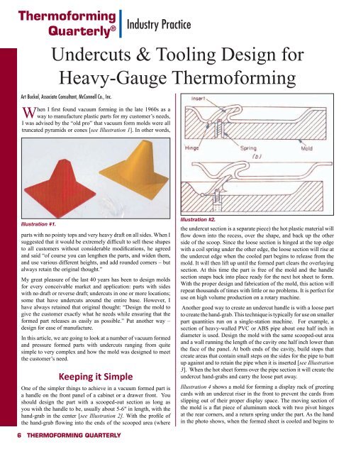
truncated pyramids or cones [see Illustration 1]. In other words,<br />
Illustration #1.<br />
parts with no pointy tops and very heavy draft on all sides. When I<br />
suggested that it would be extremely difficult to sell these shapes<br />
to all customers without considerable modifications, he agreed<br />
and said “of course you can lengthen the parts, and widen them,<br />
and use various different heights, and add rounded corners – but<br />
always retain the original thought.”<br />
My great pleasure of the last 40 years has been to design molds<br />
for every conceivable market and application: parts with sides<br />
with no draft or reverse draft; undercuts in one or more locations;<br />
some that have undercuts around the entire base. However, I<br />
have always retained that original thought: “Design the mold to<br />
give the customer exactly what he needs while ensuring that the<br />
formed part releases as easily as possible.” Put another way –<br />
design for ease of manufacture.<br />
In this article, we are going to look at a number of vacuum formed<br />
and pressure formed parts with undercuts ranging from quite<br />
simple to very complex and how the mold was designed to meet<br />
the customer’s need.<br />
Keeping it Simple<br />
One of the simpler things to achieve in a vacuum formed part is<br />
a handle on the front panel of a cabinet or a drawer front. You<br />
should design the part with a scooped-out section as long as<br />
you wish the handle to be, usually about 5-6" in length, with the<br />
hand-grab in the center [see Illustration 2]. With the profile of<br />
the hand-grab flowing into the ends of the scooped area (where<br />
Illustration #2.<br />
the undercut section is a separate piece) the hot plastic material will<br />
flow down into the recess, over the shape, and back up the other<br />
side of the scoop. Since the loose section is hinged at the top edge<br />
with a coil spring under the other edge, the loose section will rise at<br />
the undercut edge when the cooled part begins to release from the<br />
mold. It will then lift up until the formed part clears the overlaying<br />
section. At this time the part is free of the mold and the handle<br />
section snaps back into place ready for the next hot sheet to form.<br />
With the proper design and fabrication of the mold, this action will<br />
repeat thousands of times with little or no problems. It is perfect for<br />
use on high volume production on a rotary machine.<br />
Another good way to create an undercut handle is with a loose part<br />
to create the hand-grab. This technique is typically for use on smaller<br />
part quantities run on a single-station machine. For example, a<br />
section of heavy-walled PVC or ABS pipe about one half inch in<br />
diameter is used. Design the mold with the same scooped-out area<br />
and a wall running the length of the cavity one half inch lower than<br />
the face of the panel. At both ends of the cavity, build stops that<br />
create areas that contain small steps on the sides for the pipe to butt<br />
up against and to retain the pipe when it is inserted [see Illustration<br />
3]. When the hot sheet forms over the pipe section it will create the<br />
undercut hand-grabs and carry the loose part away.<br />
Illustration 4 shows a mold for forming a display rack of greeting<br />
cards with an undercut riser in the front to prevent the cards from<br />
slipping out of their proper display space. The moving section of<br />
the mold is a flat piece of aluminum stock with two pivot hinges<br />
at the rear corners, and a return spring under the part. As the hand<br />
in the photo shows, when the formed sheet is cooled and begins to<br />
6 <strong>Thermoforming</strong> QUArTerLY