Safety Manual for the Robomow RM 200 (PDF - Connox
Safety Manual for the Robomow RM 200 (PDF - Connox
Safety Manual for the Robomow RM 200 (PDF - Connox

Create successful ePaper yourself
Turn your PDF publications into a flip-book with our unique Google optimized e-Paper software.
16<br />
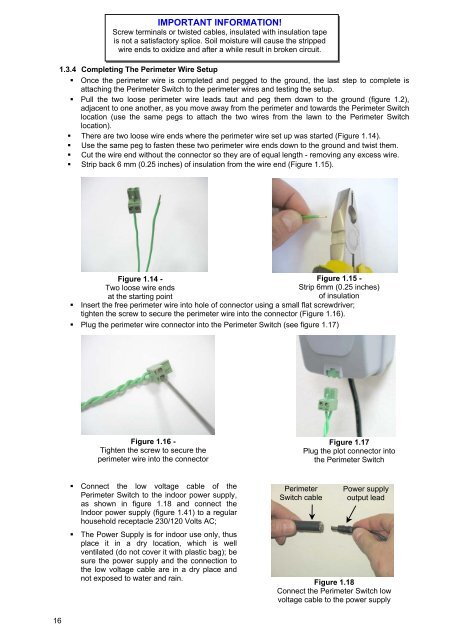
IMPORTANT INFO<strong>RM</strong>ATION!<br />
Screw terminals or twisted cables, insulated with insulation tape<br />
is not a satisfactory splice. Soil moisture will cause <strong>the</strong> stripped<br />
wire ends to oxidize and after a while result in broken circuit.<br />
1.3.4 Completing The Perimeter Wire Setup<br />
� Once <strong>the</strong> perimeter wire is completed and pegged to <strong>the</strong> ground, <strong>the</strong> last step to complete is<br />
attaching <strong>the</strong> Perimeter Switch to <strong>the</strong> perimeter wires and testing <strong>the</strong> setup.<br />
� Pull <strong>the</strong> two loose perimeter wire leads taut and peg <strong>the</strong>m down to <strong>the</strong> ground (figure 1.2),<br />
adjacent to one ano<strong>the</strong>r, as you move away from <strong>the</strong> perimeter and towards <strong>the</strong> Perimeter Switch<br />
location (use <strong>the</strong> same pegs to attach <strong>the</strong> two wires from <strong>the</strong> lawn to <strong>the</strong> Perimeter Switch<br />
location).<br />
� There are two loose wire ends where <strong>the</strong> perimeter wire set up was started (Figure 1.14).<br />
� Use <strong>the</strong> same peg to fasten <strong>the</strong>se two perimeter wire ends down to <strong>the</strong> ground and twist <strong>the</strong>m.<br />
� Cut <strong>the</strong> wire end without <strong>the</strong> connector so <strong>the</strong>y are of equal length - removing any excess wire.<br />
� Strip back 6 mm (0.25 inches) of insulation from <strong>the</strong> wire end (Figure 1.15).<br />
Figure 1.14 -<br />
Two loose wire ends<br />
at <strong>the</strong> starting point<br />
Figure 1.15 -<br />
Strip 6mm (0.25 inches)<br />
of insulation<br />
� Insert <strong>the</strong> free perimeter wire into hole of connector using a small flat screwdriver;<br />
tighten <strong>the</strong> screw to secure <strong>the</strong> perimeter wire into <strong>the</strong> connector (Figure 1.16).<br />
� Plug <strong>the</strong> perimeter wire connector into <strong>the</strong> Perimeter Switch (see figure 1.17)<br />
Figure 1.16 -<br />
Tighten <strong>the</strong> screw to secure <strong>the</strong><br />
perimeter wire into <strong>the</strong> connector<br />
� Connect <strong>the</strong> low voltage cable of <strong>the</strong><br />
Perimeter Switch to <strong>the</strong> indoor power supply,<br />
as shown in figure 1.18 and connect <strong>the</strong><br />
Indoor power supply (figure 1.41) to a regular<br />
household receptacle 230/120 Volts AC;<br />
� The Power Supply is <strong>for</strong> indoor use only, thus<br />
place it in a dry location, which is well<br />
ventilated (do not cover it with plastic bag); be<br />
sure <strong>the</strong> power supply and <strong>the</strong> connection to<br />
<strong>the</strong> low voltage cable are in a dry place and<br />
not exposed to water and rain.<br />
Perimeter<br />
Switch cable<br />
Figure 1.17<br />
Plug <strong>the</strong> plot connector into<br />
<strong>the</strong> Perimeter Switch<br />
Power supply<br />
output lead<br />
Figure 1.18<br />
Connect <strong>the</strong> Perimeter Switch low<br />
voltage cable to <strong>the</strong> power supply