Safety Manual for the Robomow RM 200 (PDF - Connox
Safety Manual for the Robomow RM 200 (PDF - Connox
Safety Manual for the Robomow RM 200 (PDF - Connox

Create successful ePaper yourself
Turn your PDF publications into a flip-book with our unique Google optimized e-Paper software.
14<br />
1.3 Perimeter Wire Setup<br />
Now, knowing <strong>the</strong> location of <strong>the</strong> Perimeter Switch and <strong>the</strong> planning of <strong>the</strong> wire layout, you can begin<br />
to setup <strong>the</strong> Perimeter Wire.<br />
1.3.1 Starting Point<br />
� Place <strong>the</strong> Perimeter Switch according to your<br />
plan, as shown in Figure 1.2;<br />
� Puncture <strong>the</strong> plastic covering of <strong>the</strong> perimeter<br />
wire and pull <strong>the</strong> wire ends with <strong>the</strong> plot<br />
connector out of <strong>the</strong> plastic covering; The<br />
connector should be connected to <strong>the</strong> wire in<br />
<strong>the</strong> polarity show in Figure 1.10;<br />
� The plastic covering is designed as a dispenser<br />
<strong>for</strong> <strong>the</strong> wire; so do not remove <strong>the</strong> wire spool<br />
from <strong>the</strong> covering;<br />
� Peg <strong>the</strong> beginning of <strong>the</strong> wire to <strong>the</strong> ground<br />
where <strong>the</strong> Perimeter Switch will be located; be<br />
sure to leave spare wire to close <strong>the</strong> loop at <strong>the</strong><br />
end of <strong>the</strong> setup (Figure 1.11);<br />
� Lay <strong>the</strong> wire from <strong>the</strong> Perimeter Switch to <strong>the</strong><br />
lawn;<br />
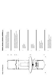
Figure 1.10 – Pull out <strong>the</strong> wire from <strong>the</strong><br />
plastic covering – do not remove <strong>the</strong><br />
covering; it is designed as a dispenser.<br />
� Start laying <strong>the</strong> wire to <strong>the</strong> counterclockwise direction when standing inside <strong>the</strong> lawn, as show in<br />
Figure 1.11.<br />
� Begin pulling <strong>the</strong> perimeter wire out of <strong>the</strong> plastic covering and lay it loosely as you walk along <strong>the</strong><br />
area of <strong>the</strong> lawn to <strong>the</strong> direction shown in Figure 1.11;<br />
Figure 1.11 –<br />
Direction of Perimeter Wire<br />
layout from <strong>the</strong> Perimeter Switch<br />
Connect <strong>the</strong> wire end to<br />
<strong>the</strong> left side of <strong>the</strong> plot<br />
connector (when facing<br />
towards <strong>the</strong> screws)<br />
Perimeter wire layout in<br />
clockwise direction (as viewed<br />
from <strong>the</strong> inner side of <strong>the</strong> lawn)