Detailed User's Manual - Sans Digital
Detailed User's Manual - Sans Digital
Detailed User's Manual - Sans Digital

Create successful ePaper yourself
Turn your PDF publications into a flip-book with our unique Google optimized e-Paper software.
EliteRAID<br />
ER104I<br />
&<br />
MobileRAID<br />
MR4I<br />
DETAILED USER’S MANUAL
Forewords<br />
About this manual<br />
Thank you for using products from <strong>Sans</strong> <strong>Digital</strong>.<br />
This manual will introduce the <strong>Sans</strong> <strong>Digital</strong> iSCSI product. Before using <strong>Sans</strong> <strong>Digital</strong> iSCSI product,<br />
you are advised to read this manual fi rst. All information contained in this manual has been carefully<br />
confi rmed before printing, but the actual product specifi cations shall be in accordance with those at the<br />
time of delivery; any update to product specifi cations or relevant information may be found on<br />
www.sansdigital.com, and no separate notifi cation will be made.<br />
If you have any query regarding the products of <strong>Sans</strong> <strong>Digital</strong>, or you would like the latest product<br />
information, please contact us at support@sansdigital.com, and we shall give you a reply as soon as<br />
possible.<br />
Copyright © <strong>Sans</strong> <strong>Digital</strong>. All rights reserved.
ER104I Quick Install Guide<br />
1. Package Contents<br />
After you open the outer package, make sure that the following items are in the box:<br />
‧ER104I product body<br />
‧AC Power Cord<br />
‧RS-232 Port Cable<br />
‧CD<br />
‧User <strong>Manual</strong><br />
‧Accessory Kit<br />
2. Hardware Installation<br />
Please follow the procedures to complete the hardware installation of ER104I.<br />
Step 1<br />
Open the outer package and take out the product. (Make sure the related accessories<br />
and the product are not damaged or missing. If you have any questions, please<br />
contact the us, www.sansdigital.com or support@sansdigital.com)<br />
Step 2<br />
Mount the product to the rack. Make sure that the ventilation fan is not obstructed and<br />
appropriate ventilation space is provided around the product. (Do not place the product<br />
to any environment that may cause damage to the product)<br />
Step 3<br />
Take out the tray and install your hard disk in it. Make sure to fasten the hard disk securing<br />
screws to prevent damages caused by unnecessary movement.
Step 4 Once the installation is completed, insert the tray back and fi x it fi rmly in the proper place.<br />
Step 5<br />
Connect the cables to the corresponding ports. Make sure that you have connected the<br />
corresponding cables to two Gigabit ports, LAN or RS-232 port and Extension port (optional).<br />
Then connect the power cord.<br />
Step 6<br />
Hardware installation is completed. You can power on the system to start the related setup<br />
and application through LAN port or RS232 port. (Default account and password:<br />
admin / 1234, IP address: 192.168.0.1)<br />
Complete! You may start the configurations of the system. Please refer to Chapter 4.
MR4I Quick Install Guide<br />
1. Package Contents<br />
After you open the outer package, make sure that the following items are in the box:<br />
‧MR4I product body<br />
‧AC Power Cord<br />
‧RS-232 Port Cable<br />
‧CD<br />
‧User <strong>Manual</strong><br />
‧Accessory Kit<br />
2. Hardware Installation<br />
Please follow the procedures to complete the hardware installation of MR4I.<br />
Step 1<br />
Open the outer package and take out the product. (Make sure the related accessories<br />
and the product are not damaged or missing. If you have any questions, please<br />
contact the us, www.sansdigital.com or support@sansdigital.com)<br />
Step 2<br />
Place the product on a fl at and stable surface. Make sure that the ventilation fan is not obstructed<br />
and appropriate ventilation space is provided around the product. (Do not place the product to<br />
any environment that may cause damage to the product)<br />
Step 3<br />
Take out the tray and install your hard disk in it. Make sure to fasten the hard disk securing<br />
screws to prevent damages caused by unnecessary movement.
Step 4 Once the installation is completed, insert the tray back and fi x it fi rmly in the proper place.<br />
Step 5<br />
Connect the cables to the corresponding ports. Make sure that you have connected the<br />
corresponding cables to two Gigabit ports, LAN or RS-232 port and Extension port (optional).<br />
Then connect the power cord.<br />
Step 6<br />
Hardware installation is completed. You can power on the system to start the related setup<br />
and application through LAN port or RS232 port. (Default account and password: admin /<br />
1234, IP address: 192.168.0.1)<br />
Complete! You may start the configurations of the system. Please refer to Chapter 4.
Contents<br />
Chapter 1 RAID Introduction.................................................................. 10<br />
1.1 What is RAID.............................................................................. 10<br />
1.2 RAID Functions............................................................................. 10<br />
1.3 RAID Levels and Comparisons.......................................................... 10<br />
Chapter 2 iSCSI Introduction and Glossary.......................................... 12<br />
2.1 What is iSCSI.............................................................................. 12<br />
2.2 Using iSCSI.................................................................................. 12<br />
2.3 Glossary...................................................................................... 13<br />
Chapter 3 Installation.............................................................................. 14<br />
3.1 Notice Before Installation................................................................. 14<br />
3.1.1 <strong>Sans</strong> <strong>Digital</strong> iSCSI Series Products Features......................................... 14<br />
3.1.2 Verifying the related equipments........................................................ 14<br />
3.2 Management Methods.................................................................... 15<br />
3.2.1 Web GUI (Graphic User Interface)..................................................... 15<br />
3.2.2 RS-232 Connection Port.................................................................. 18<br />
3.2.3 Remote Control - Secure Shell.......................................................... 21<br />
3.3 System Control............................................................................. 22<br />
3.3.1 LCM (SL5650).............................................................................. 22<br />
3.3.2 System Buzzer.............................................................................. 23<br />
Chapter 4 GUI Overview.......................................................................... 24<br />
4.1 GUI Architecture............................................................................ 24<br />
4.2 Login.......................................................................................... 25<br />
4.3 Quick install................................................................................. 26<br />
4.4 System confi g............................................................................... 27<br />
4.4.1 System name............................................................................... 27<br />
4.4.2 IP address................................................................................... 28<br />
4.4.3 iSCSI.......................................................................................... 28<br />
4.4.4 Login Confi g................................................................................. 28<br />
4.4.5 Password.................................................................................... 29<br />
4.4.6 Date........................................................................................... 29<br />
4.4.7 E-Mail......................................................................................... 29<br />
4.4.8 Simple Network Management Protocol (SNMP)..................................... 30<br />
4.4.9 System log Server.......................................................................... 30<br />
4.4.10 Event log..................................................................................... 30<br />
4.5 iSCSI confi g................................................................................. 31<br />
4.5.1 Entity property............................................................................... 31<br />
4.5.2 NIC............................................................................................ 31<br />
4.5.3 Node.......................................................................................... 32<br />
4.5.4 Session....................................................................................... 32<br />
4.5.5 CHAP account.............................................................................. 32<br />
4.6 Volume confi g............................................................................... 33<br />
4.6.1 Physical disk................................................................................. 33<br />
4.6.2 Volume group (VG)......................................................................... 35
4.6.3 User data volume (UDV).................................................................. 35<br />
4.6.4 Cache volume (CV)........................................................................ 36<br />
4.6.5 Logical unit number........................................................................ 37<br />
4.6.6 Example...................................................................................... 37<br />
4.7 Enclosure Management.................................................................. 45<br />
4.7.1 SES confi g................................................................................... 45<br />
4.7.2 Hardware Monitor.......................................................................... 45<br />
4.7.3 Hard Drive S.M.A.R.T. Function Support.............................................. 46<br />
4.7.4 UPS........................................................................................... 46<br />
4.8 Maintenance................................................................................ 47<br />
4.8.1 Upgrade...................................................................................... 47<br />
4.8.2 Info............................................................................................ 48<br />
4.8.3 Reset to default............................................................................. 48<br />
4.8.4 Congif import & export.................................................................... 48<br />
4.8.5 Shutdown.................................................................................... 48<br />
4.9 Logout........................................................................................ 49<br />
Chapter 5 Advanced Operation.............................................................. 50<br />
5.1 Rebuild........................................................................................ 50<br />
5.2 VG Migration and Expansion............................................................ 51<br />
5.3 UDV Expansion............................................................................. 52<br />
5.4 Disk roaming................................................................................ 52<br />
5.5 Support Microsoft MPIO and MC/S..................................................... 52<br />
Chapter 6 Application Description......................................................... 53<br />
6.1 Sharing Resources......................................................................... 53<br />
6.2 Easy Storage Capacity Expansion...................................................... 54<br />
6.3 Remote Access............................................................................. 54<br />
Appendix<br />
A. Certifi cation list.............................................................................. 55<br />
B. Event notifi cations.......................................................................... 57<br />
C. Using notices................................................................................ 60<br />
D. Microsoft iSCSI Initiator................................................................... 61<br />
E. MPIO and MC/S confi gure instructions................................................ 66<br />
F. QLogic QLA4010C confi gure instructions............................................. 82
Chapter 1<br />
RAID Introduction<br />
1.1 What is RAID<br />
It is inevitable that a single hard disk, either with SCSI or IDE interface, will suffer the compatibility<br />
problem between the motor rotational speed and the transfer interface. As a result, an Ultra160 SCSI or<br />
ATA100 IDE hard disk can only achieve the transfer rate of up to 30MB/Sec at the bandwidth of<br />
100MHz.<br />
In addition, the life span of a hard disk is limited. Once a hard disk is damaged, it is likely to lead to the<br />
system crash and data loss. Above mentioned are two severe problems in network system architecture.<br />
These factors have encouraged the creation of RAID (Redundant Arrays of Inexpensive / Independent<br />
Disks), a technology that combines multiple inexpensive and independent hard disks into an array of<br />
harddisks so as to increase data transfer performance and storage effi ciency.<br />
RAID implements the mechanisms such as Striping or Mirroring plus Parity Checking, to combine two<br />
or more physical hard disks into one virtual/logical disk array that allows On-line, quick access, huge<br />
capacity and fault tolerance. If one of the hard disks in the array is damaged, the system continues to<br />
operate using the remaining working hard disks, resulting in no system crash or data loss. In summary,<br />
RAID technology increases the performance and data security in network system architecture.<br />
1.2 RAID Functions<br />
‧Expanding storage capacity<br />
‧Increasing data transfer speed<br />
‧Saving cost<br />
‧Inherent Fault Tolerance<br />
‧Hot Swap<br />
‧Auto-Rebuild<br />
‧Hot Spare<br />
‧On-line Capacity Expansion<br />
1.3 RAID Levels and Comparisons<br />
With the development of RAID technologies, users now have more options for RAID levels. Some<br />
vendors even have proprietary names for RAID levels. Generally, RAID levels include RAID 0, 1, 3, 5, 6,<br />
0+1, 10, 30, 50, 60 and JBOD (Just a Bunch Of Disks).<br />
The following is a comparison of some commonly used RAID levels.<br />
RAID Level<br />
0<br />
Basic Operation<br />
Method<br />
Striping data across<br />
each drive<br />
1 Mirroring<br />
0+1<br />
Mirroring data to<br />
another drive and<br />
stripping across the<br />
drive<br />
Hard Disk Available<br />
Capacity<br />
Total capacity of all<br />
the hard disks<br />
Half of total capacity<br />
of all the hard disks<br />
Half of total capacity<br />
of all the hard disks<br />
Data Reliability Data Transfer Speed<br />
Minimum Number<br />
of Hard Disks<br />
Low Highest 2<br />
High Lower 2<br />
Very High High 4<br />
10 RAID Introduction
3<br />
5<br />
3+Spare<br />
5+Spare<br />
6<br />
Stores parity<br />
information on<br />
independent disk<br />
Stores parity<br />
information on all the<br />
hard disks<br />
Stores parity<br />
information on<br />
independent hard disk<br />
& spare disk.<br />
Stores parity<br />
information on all the<br />
hard disks & spare<br />
disk.<br />
Stores parity<br />
information on all the<br />
hard disks<br />
Total capacity of all<br />
the hard disks minus<br />
one disk capacity<br />
Total capacity of all<br />
the hard disks minus<br />
one disk capacity<br />
Total capacity of all<br />
the hard disks minus<br />
two disks capacity<br />
Total capacity of all<br />
the hard disks minus<br />
two disks capacity<br />
Total capacity of all<br />
the hard disks minus<br />
two disks capacity<br />
High Very High 3<br />
High Very High 3<br />
Very High High 4<br />
Very High High 4<br />
Very High High 4<br />
For more information of RAID, refer to our website at www.sansdigital.com<br />
RAID Introduction 11
Chapter 2 iSCSI Introduction and Glossary<br />
2.1 What is iSCSI<br />
SCSI (Small Computer Standard Interface) is an ANSI standard parallel interface used by a computer<br />
to link up with peripheral devices. As it offers faster transfer rates than other standard interfaces, it is<br />
commonly used in workstations and servers as the interface of HDD and other storage devices.<br />
A iSCSI (Internet SCSI) is a protocol that integrates SCSI protocol into TCP/IP packet in order to link<br />
storage device with servers over a network. iSCSI is capable of providing high-effi ciency SANs (Storage<br />
Area Networks) over standard IP network such as LAN, WAN or Internet.<br />
Conventional SANs generally refer to the storage area networks under Fiber-Channel. Yet to response<br />
to the effects of iSCSI, currently SANs are divided into FC-SANs and IP-SANs. IP-SAN uses iSCSI<br />
transfer protocol to add storage capacity unlimitedly to a server over the Internet, regarded as a real<br />
storage network system.<br />
The storage capacity of IP-SANs can be expanded using various storage systems from various vendors.<br />
Furthermore, under SANs, any network types (such as Ethernet, High Ethernet or Fast Ethernet) and<br />
various operation systems (such as Microsoft Windows, Linux, Solaris and etc) can be supported. IP-<br />
SANs also provides the mechanisms for security, data duplication, multi-channel, high-effi ciency and etc.<br />
2.2 Using iSCSI<br />
A connection using storage protocol such as iSCSI requires “two ends”, a “Initiator” and a “target”. In the<br />
iSCSI fi eld, they are called “iSCSI initiator” and “iSCSI target”.<br />
iSCSI initiator asks for operation from all SCSI, for example, read and write. iSCSI usually locates in the<br />
Host side or sever side.<br />
On the other hand, iSCSI target refers to the storage equipments or the devices used for managing or<br />
allocating capacity. It is a device for executing SCSI commands. An iSCSI target can be a disk, tape or<br />
disk array.<br />
12 RAID Introduction
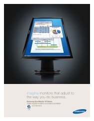
Figure 2.2.1<br />
iSCSI initiator is essential to the host side. It is controlling SCSI in an iSCSI implementation. Its role can<br />
be played as either software or hardware (HBA). Please refer to the iSCSI HBA card list in Appendix A to<br />
confi rm if your HBA card is supported. Initiator software adopts standard TCP/IP protocol and Ethernet<br />
facilities while iSCSI HBA card uses vendor-proprietary iSCSI and TCP/IP protocols.<br />
iSCSI HBA card vendors will provide proprietary initiator tools. Please refer to your HBA card user<br />
manual for detailed information.<br />
Users can download Microsoft iSCSI initiator software at the following URL:<br />
http://www.microsoft.com/downloads/details.aspxFamilyID=12cb3c1a-15d6-4585-b385-befd1319f825&<br />
DisplayLang=en<br />
Please refer to Appendix D Microsoft iSCSI initiator for the installation instructions of Microsoft iSCSI initiator.<br />
Linux OS provides iSCSI initiator as well. Refer to the URL below:<br />
Instructions web page : http://linux-iscsi.sourceforge.net/<br />
Download link : http://sourceforge.net/project/showfi les.phpgroup_id=26396<br />
Instructions document : http://www.cuddletech.com/articles/iscsi/iscsiref.pdf<br />
For Mac operation system, please refer to the URL below:http://www.attotech.com/xtend.html<br />
For software used on other operation system, please refer to the related instructions on the respective<br />
websites.<br />
2.3 Glossary<br />
The following terms will be used throughout this manual:<br />
RAID Redundant Array of Independent Disks DS Dedicated Spare disks<br />
PD Physical Disk GS Global Spare disks<br />
VG Volume Group DC Dedicated Cache<br />
UDV User Data Volume GC Global Cache<br />
CV Cache Volume DG DeGrade mode<br />
LUN Logical Unit Number S.M.A.R.T. Self-Monitoring Analysis and Reporting<br />
Technology.<br />
GUI Graphic User Interface. WWN World Wide Name.<br />
WT Write-Through HBA Host Bus Adapter.<br />
WB Write-Back MPIO Multi-Path Input/Output.<br />
RO Read-Only MC/S Multiple Connections per Session<br />
S.E.S SCSI Enclosure Services NIC Network Interface Card<br />
iSCSI Internet Small Computer Systems Interface LACP Link Aggregation Control Protocol<br />
MTU Maximum Transmission Unit CHAP Challenge Handshake Authentication Protocol<br />
iSNS<br />
Internet Storage Name Service<br />
RAID Introduction 13
Chapter 3 Installation<br />
3.1 Notice Before Installation<br />
3.1.1 <strong>Sans</strong> <strong>Digital</strong> iSCSI Series Products Features<br />
<strong>Sans</strong> <strong>Digital</strong> iSCSI Series Products are high-performance RAID system with the features as follows:<br />
‧Dual Gigabit channels design<br />
‧eSATA expansion interface<br />
‧Supports RAID 6 level<br />
‧Supports hot-swap<br />
‧N-way mirroring<br />
‧GUI operator interface<br />
‧Online capacity expansion and RAID level conversion<br />
‧Global/dedicated cache confi guration by volume<br />
‧Supports S.M.A.R.T<br />
‧Supports SES<br />
‧Disk roaming<br />
‧MPIO ready (initiator driver or HBA card support needed)<br />
‧MC/S ready (initiator driver or HBA card support needed)<br />
‧Supports CHAP authentication<br />
<strong>Sans</strong> <strong>Digital</strong> iSCSI Series products can be applied on different RAID level by connecting to a main system<br />
via iSCSI interface. <strong>Sans</strong> <strong>Digital</strong> iSCSI Series products provide reliable data security and supports RAID<br />
6 level. RAID 6 level allows two damaged hard disks without affecting current data. Data in the damaged<br />
hard disk can be restored by the data in the working hard disks.<br />
By providing high-performance and protecting your data, <strong>Sans</strong> <strong>Digital</strong> iSCSI Series Products are the most<br />
cost-effective and best solution in the network data storage backup field for small and medium business.<br />
3.1.2 Verifying the related equipments<br />
Before you install the related products, please verify the following items first:<br />
‧ When you open the package and take out the hardware components, please check if any accessory is<br />
missing or damaged<br />
‧ Refer to Appendix A Certification List to verify if your hardware devices are supported<br />
‧ A server equips with Ethernet card or iSCSI HBA card<br />
‧ CAT 5e or CAT 6 network cable used in the management and iSCSI port. We suggest you using<br />
CAT 6 network cable for optimal performance<br />
‧ Plan your storage system architecture, such RAID and spare information, in advance<br />
‧ The information on the management port and the iSCSI port. To use a static IP address, please prepare<br />
the information about the static IP address, subnet mask and default gateway<br />
‧ High-speed network switch (recommended) or a high-speed network switch featuring VLAN/LCAP/<br />
Trunking functions<br />
‧ CHAP security information, including the CHAP user name and password (optional)<br />
14 RAID Introduction
‧ Complete all the hardware installation before booting the system. The connection to the controller port,<br />
management port and iSCSI port should be completed fi rst<br />
3.2 Management Methods<br />
You can manage the <strong>Sans</strong> <strong>Digital</strong> iSCSI Series Products by one of the following three methods. Each<br />
method is described as follows:<br />
3.2.1 Web GUI (Graphic User Interface)<br />
<strong>Sans</strong> <strong>Digital</strong> iSCSI Series Products support Graphic User Interface (GUI) for system management. Before<br />
getting started, make sure the related network port is connected. If you want to use a static IP address,<br />
make sure the IP address is not confl icting with other IP address. You can use the “ping” command to<br />
verify if IP address confliction occurs.<br />
The default IP address of <strong>Sans</strong> <strong>Digital</strong> iSCSI Series Products is 192.168.0.1. The following instructions<br />
describe how to start your initial setup by confi guring a static IP address in Windows XP system.<br />
Step 1<br />
First, verify if IP address confl iction occurs. Click Start→Run→input ping xxx.xxx.xxx.xxx (the IP<br />
address you are going to use). If you get a reply of “Request time out.”, then you can use the IP<br />
address. It is recommended that you may also consult with your MIS personnel directly for the<br />
related IP address information.<br />
RAID Introduction 15
Step 2<br />
Confi gure the domain. Click Start→Settings→Network Connections. A dialog window for your<br />
current network connection will appear. Select “Network Connections” and then click “Properties”.<br />
Step 3<br />
Select “Internet Protocol (TCP/IP)” and click “Properties”. A dialog window for IP address<br />
settings will appear.<br />
16 RAID Introduction
Step 4<br />
Confi gure the IP address, subnet mask, gateway and DNS. You can consult with the MIS<br />
personnel in your company for the related IP address.<br />
Step 5<br />
After the confi guration, click “OK” to complete the settings. (If you need to change the IP<br />
address in the future, you should make sure that the IP addresses used by <strong>Sans</strong> <strong>Digital</strong> iSCSI<br />
Series Products are in the same domain to ensure the proper system operation.)<br />
Step 6 Login the system. The default IP address of <strong>Sans</strong> <strong>Digital</strong> iSCSI Series Products is 192.168.0.1.<br />
Open your web browser and input:<br />
RAID Introduction 17
http://192.168.0.1<br />
To use the system for the fi rst time, click any of the functions to pop up the screen requesting for account<br />
and password. The default username and password are as follows:<br />
Login Username: admin ; Default Password: 1234<br />
3.2.2 RS-232 Connection Port<br />
The system can also be managed and confi gured via the RS-232. In case you have forgotten the IP<br />
address you have confi gured, you can then use RS-232 port to enter the system for confi gure. The<br />
following instructions are based on Windows XP environment.<br />
Step 1<br />
Step 2<br />
Please make connection by using RS-232 cable provided in the Accessory Kit. Once the<br />
connection is completed, switch the power on.<br />
Click Start→Programs→Accessories→Communications→HyperTerminal. To confi gure the<br />
terminal settings. The fi rst step is to give a name for this terminal setting.<br />
18 RAID Introduction
Step 3<br />
Select the connection port.<br />
Step 4<br />
Confi gure the related settings.<br />
RAID Introduction 19
Bits per second: 115200<br />
Data bits: 8 bite<br />
Parity: None<br />
Stop bits: 1<br />
Flow control: None<br />
Step 5<br />
Select the terminal type. Please click File→Properties→Settings. Specify the terminal type as<br />
vt100. Then click “OK” to complete the connection.<br />
Step 6<br />
After the connection, input the username and password and then login. The following operations<br />
20 RAID Introduction
are similar to the operations via web-based GUI. Please refer to Chapter 4 for instructions.<br />
SANS DIGITAL<br />
Login Username: admin<br />
Default Password: 1234<br />
3.2.3 Remote Control - Secure Shell<br />
SSH (secure shell) allows remote login to <strong>Sans</strong> <strong>Digital</strong> iSCSI Series Products<br />
You can download SSH end user software via the following websites:<br />
SSHWinClient WWW : http://www.ssh.com/<br />
Putty WWW : http://www.chiark.greenend.org.uk/<br />
Host name: 192.168.0.1<br />
Login Username: admin<br />
Default Password: 1234<br />
SANS DIGITAL<br />
Remind : <strong>Sans</strong> <strong>Digital</strong> iSCSI Series Products support SSH for remote control. To use SSH functions, IP address and password are<br />
required for login.<br />
RAID Introduction 21
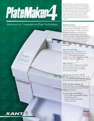
3.3 System Control<br />
3.3.1 LCM (SL5650)<br />
Use the four function keys, (Up), (Down), ESC (Escape) and ENT (Enter) to control LCM (LCD<br />
Control Module). After booting up the system, the following screen will be displayed.<br />
xxx.xxx.xxx.xxx<br />
IntelliRAID<br />
After pressing ENT (Enter) key, you can use (Up) and (Down) keys to select a LCM function.<br />
If there is any alarm or error message, LCM will show the related information on the screen to provide<br />
users with more information.<br />
Each LCM function is described as follows:<br />
Alarm Mute<br />
To turn off the alarm sound when an error occurs<br />
Reset/Shutdown<br />
To reset or shutdown the controller<br />
Quick Install<br />
To use “Quick Install” to set up a volume by three steps. Please refer to section 4.3 for confi gure via the webbased<br />
GUI<br />
View IP Setting<br />
To view current IP address, subnet mask and gateway<br />
Change IP Confi g<br />
To set up the IP address, subnet mask and gateway. You can choose to use DHCP server (for IP address<br />
allocation) or manually specify the IP address<br />
Reset to Default<br />
To restore factory defaults:<br />
Default Password: 1234<br />
Default IP address: 192.168.0.1<br />
Default subnet mask: 255.255.255.0<br />
Default gateway: 192.168.0.254<br />
22 RAID Introduction
LCM architecture reference diagram<br />
[Alarm Mute] [Yes No]<br />
[Reset/Shutdown]<br />
[Reset] [Yes No]<br />
[Shutdown] [Yes No]<br />
[Quick Install]<br />
RAID 0<br />
(RAID 1/RAID 3/<br />
RAID 5/RAID 6)<br />
xxxxxx MB<br />
Volume Size<br />
(xxxxxx MB)<br />
Adjust Volume<br />
Size<br />
Apply The Confi g [Yes No]<br />
<strong>Sans</strong> <strong>Digital</strong><br />
IntelliRAID<br />
[View IP Setting]<br />
[IP Config]<br />
[Static IP]<br />
[IP Address]<br />
[192.168.000.001]<br />
[IP Subnet Mask]<br />
[255.255.255.0]<br />
[IP Gateway]<br />
[192.168.000.254]<br />
[DHCP] [Yes No]<br />
[IP Address]<br />
Adjust IP address<br />
[Change IP Confi g]<br />
[Static IP]<br />
[IP Subnet Mask]<br />
[IP Gateway]<br />
Adjust Submask IP<br />
Adjust Gateway IP<br />
[Apply IP Setting] [Yes No]<br />
[Reset to Default] [Yes No]<br />
Note : Before powering off, please execute “Shutdown” to fl ush the data from the cache<br />
3.3.2 System Buzzer<br />
The system buzzer features are described as follows:<br />
1. The system buzzer alarms to confi rm that system boots up successfully<br />
2. The system buzzer alarms continuously when system failure or error occurs. The alarm can be<br />
stopped via the mute option (Alarm Mute)<br />
RAID Introduction 23
Chapter 4 GUI Overview<br />
4.1 GUI Architecture<br />
The following is the GUI architecture:<br />
Quick Install Step 1 / Step 2 / Step 3 / Confi rm<br />
System Config<br />
iSCSI Config<br />
Volume config<br />
System name System name<br />
IP address DHCP / Static / HTTP port / HTTPS port / SSH port<br />
iSCSI iSNS / Authentication / Link aggregation or Multi-homed / IP settings / Default gateway / Set MTU<br />
Language Auto Detect / English / Simple Chinese<br />
Log config Auto Logout / Login Lock<br />
Password Old password / Password / Confi rm<br />
Date Date / Time / Time zone / Daylight saving / NTP / Server<br />
Mail Mail-from address / Mail-to address / SMTP relay / Authentication / Send test mail<br />
SNMP SNMP trap address / Community<br />
System log server Server IP / Hostname / Port / Facility / Event Level<br />
Event log Filter / Mute / Clear / Download<br />
Entity Property Entity name / iSNS IP<br />
NIC <br />
Name / DHCP / IP Address Netmask / Gateway / MTU<br />
/ MAC Address / Link / Entity Name<br />
Node Name / Auth<br />
Session Initiator Name / TPGT / Error Recovery Level / Error Recovery Count<br />
CHAP account User<br />
Physical disk Free disc / Global spares / Dedicated spares / More information<br />
Volume group Create / Delete / More information / Rename / Migrate<br />
User data volume <br />
Create / Delete / Attach LUN / More information / Rename / Extend / Set read/write mode / Set<br />
priority<br />
Cache volume Create / Delete / More information / Resize<br />
Logical unit Attach / Detach<br />
Enclosure management<br />
Maintenance<br />
Logout<br />
SES Config Enable / Disable<br />
Hardware Monitor Item / Information / Confi rm<br />
S.M.A.R.T. S.M.A.R.T. for physical disks<br />
UPS UPS Type / Shutdown Battery Level / Shutdown Delay / Shutdown UPS<br />
Upgrade Browse the fi rmware to upgrade<br />
Info System information<br />
Reset to default Reset to factory default<br />
Config Import & Export Import / Export / Import File<br />
Shutdown Reboot / Shutdown<br />
24 RAID Introduction
4.2 Login<br />
<strong>Sans</strong> <strong>Digital</strong> iSCSI Series Products supports graphic user interface (GUI) to manage the system. Make<br />
sure the network cable is already connected and confi gured to the same domain as your current related<br />
devices. Please refer to 3.2.1 for related confi gures. The following descriptions are examples based on<br />
the default IP address: 192.168.0.1. Please open your web browser and input:<br />
http://192.168.0.1<br />
To use the system for the fi rst time, click any of the functions to pop up the dialog window requesting for<br />
account and password. The default account and password are as follows:<br />
Login account: admin<br />
Default Password: 1234<br />
After login, you can choose a function from the list to the left side of the window for related confi gures.<br />
There are four indicators at the top-right corner of the window. Each indicates:<br />
1. RAID light : Green indicates RAID is working properly. Red indicates RAID error.<br />
2. Temperature light: Green indicates normal. Red indicates abnormal system temperature.<br />
3. Voltage light : Green indicates normal. Red indicates abnormal voltage status. Please refer to<br />
4.6.2 for more details.<br />
4. UPS : Green indicates normal. Red indicates abnormal UPS status.<br />
RAID Introduction 25
4.3 Quick install<br />
You can use “Quick install” function for quick confi gure. On RAID levels 0, 1, 3, 5 and 6, the system will<br />
automatically calculate the maximum available capacity, which is subject to the number of your hard<br />
disks and currently available capacity.<br />
Step 1<br />
Select “Quick install”, the system will ask you to confi gure the RAID level, as shown in<br />
to fi gure 4.3.1. After confi guring the RAID level, click “<br />
” to enter next page<br />
to confi gure “LUN”.<br />
Figure 4.3.1<br />
Step 2<br />
Step 3<br />
Please select a Logical Unit Number (LUN). The wildcard “*” indicates that every host is<br />
allowed to access this capacity. You can change the volume size in this page. The maximum<br />
volume size will be automatically shown on this page. Input a value specifi ed a size<br />
less than or equal to the maximum volume size, and click “ ”.<br />
Confi rmation page. The system will display all the related information as shown in<br />
Figure 4.3.2. If the information is correct, click “ ”.<br />
Figure 4.3.2<br />
26 RAID Introduction
4.4 System config<br />
“System confi g” function allows you to confi gure the basic functions of the system.<br />
4.4.1 System name<br />
Figure 4.4<br />
Select “System name” to change system name. The default System name is in accordance with the<br />
product name and serial number of the system. For example: SANSDIGITAL-000001.<br />
Figure 4.4.1<br />
RAID Introduction 27
4.4.2 IP address<br />
Select “IP address” to change the IP address for remote control page. You can choose DHCP (to obtain<br />
IP address from DHCP server) or static IP to change the HTTP, HTTPS and SSH ports.<br />
4.4.3 Language<br />
Figure 4.4.2<br />
Select “Language” to setup the GUI language.<br />
4.4.4 Login Config<br />
Figure 4.4.3<br />
Select “Login confi g” to confi gure the time of single login and auto logout. Single login can prevent<br />
multiple users from simultaneously accessing the management console.<br />
1. Auto logout: The options include (1) Disable (2) 5 min (3) 30 min (4) 1 hour. If a user idles after the<br />
specifi ed time elapsed, the system will automatically logout to allow other users to login.<br />
Figure 4.4.4<br />
2. Login block: Disable / Enable. When login block is enabled, only one user is allowed to login/change<br />
the system settings.<br />
28 RAID Introduction
4.4.5 Password<br />
Click “Password” to change the administrator password. Input the original password fi rst and then input<br />
your new password two twice.<br />
4.4.6 Date<br />
Figure 4.4.5<br />
Click “Date” to confi gure current date and time.(We recommend you confi gure it before using the system<br />
to ensure the time consistency across the network.)<br />
4.4.7 E-Mail<br />
Figure 4.4.6<br />
Click “Mail” to input up to 3 E-mail addresses for receiving the event notifi cation. Mail servers will check<br />
“Mail-from address” and block spam mails. Please fi ll the necessary fi elds and select “Send test mail” to<br />
verify the E-mail notifi cation function works properly.<br />
Figure 4.4.7<br />
RAID Introduction 29
4.4.8 Simple Network Management Protocol (SNMP)<br />
Select “SNMP” to confi gure SNMP (Simple Network Management Protocol) trap messages. It allows up<br />
to 3 SNMP trap message addresses. The default community confi gure is “public”.<br />
4.4.9 System log Server<br />
Figure 4.4.8<br />
The System log server supports remote access to the disk array system’s log. It allows system event log<br />
to be recorded into fi les and be sent to those operating systems with the “syslogd” applications.<br />
If this functionality is required, the ER104I/MR4I set as the “Target”. Please follow the screen below and<br />
fi ll out the information necessary with 514 TCP port set as the communication port.<br />
Currently, both Windows & MAC do not support system log server functions, if you require this function,<br />
please contact Windows or MAC support for further details or updates. A third party program support<br />
syslogd may be available.<br />
4.4.10 Event log<br />
Figure 4.4.9<br />
Event log contain system event of the unit. Click “Event log” to view the event messages. Click “Filter”<br />
to select the log type to be displayed. Click “Download” button to save the whole event log as a text fi le<br />
“log-xxxx.txt”. Click “Clear” button to clear the whole event log. Click “Mute” button to stop system alerts.<br />
Figure 4.4.10.1<br />
30 RAID Introduction
There are three methods to display the event log: “Show events” in the event log page, “Pop up events”<br />
in the pop-up window in the web page, and “Show on LCM” (SL5650). You can select a preferred one.<br />
4.5 iSCSI config<br />
Figure 4.4.10.2<br />
Select the “iSCSI confi g” allows you to confi gure the related iSCSI settings.<br />
4.5.1 Entity property<br />
Figure 4.5<br />
Once the Entity name has been displayed, you may input the iSNS IP address. Through the iSNS<br />
function, the iSCSI storage system is able to pass the related management information to the iSNS<br />
server to provide better management of overall iSCSI network.<br />
iqn.2001-08.com.sansdigital:iscsi-000a40189<br />
Figure 4.5.1<br />
4.5.2 NIC<br />
This function allows the two communication ports for two IP addresses. Select to confi gure the<br />
usage of the DHCP or the static IP address. Select to confi gure the default gateway IP address.<br />
Select to confi gure the MTU value. Static IP address is highly recommended.<br />
Figure 4.5.2<br />
RAID Introduction 31
4.5.3 Node<br />
Displays Node name. Select<br />
to enable or disable the CHAP function.<br />
iqn.2001-08.com.sansdigital:iscsi-000a40189:default-target<br />
Figure 4.5.3<br />
4.5.4 Session<br />
Displays the number of users connected to the system. Select<br />
as “Initiator IP”, ”Initiator name” and ”Authentication”.<br />
to see the related information such<br />
Figure 4.5.4.1<br />
Figure 4.5.4.2<br />
4.5.5 CHAP account<br />
Sets up related information of CHAP. Select<br />
to add a new CHAP user. Select<br />
to delete an existing user. Select to further set up related confi guration of each<br />
sansdigital<br />
user.<br />
sansdigital<br />
Figure 4.5.5<br />
32 RAID Introduction
4.6 Volume config<br />
“Volume confi g” allows you to confi gure any volume related functionalities of the system.<br />
4.6.1 Physical disk<br />
Figure 4.6<br />
Enter the “Physical disk” option to view the status of hard disks installed in the system.<br />
The following are operation tips:<br />
1. Multiple selections. Select one or more hard disks by clicking the checkboxes. Or click the checkbox<br />
at the top left corner for the system to select all the disks automatically. Ticking again will select none.<br />
2. The list will not appear if there is no Volume Group (VG) or VG under RAID 0 or JBOD mode. This is<br />
because the dedicated disk cannot be confi gured under these RAID levels.<br />
3. Three functions, “ ”, “ ” and “ ”, are allow<br />
multiple selection.<br />
Figure 4.6.1<br />
RAID Introduction 33
‧Physical disk fi eld description:<br />
Slot<br />
WWN<br />
Size (MB)<br />
VG Name<br />
The slot number of the hard disk. The blue button next to the number indicates “More Information” function.<br />
Clicking it shows the details of the hard disk.<br />
World Wide Name.<br />
Disk volume<br />
Associated Volume Group name.<br />
Status<br />
Disk state:<br />
“GOOD” The hard disk is good.<br />
“DEFECT” The hard disk has errors.<br />
“FAIL” The disk fails to function properly.<br />
Status 1<br />
Status 2<br />
“RD” RAID Disk. This hard disk has been confi gured with a RAID level.<br />
“FR” Free disk. This hard disk is free for use.<br />
“DS” Dedicated Spare. This disk has been confi gured to be the dedicated spare of the VG.<br />
“GS” Global Spare. This disk has been confi gured to be a global spare of all VGs.<br />
“RS” Reserve. The disk contains the VG information but cannot be used. It is caused by incomplete VG<br />
confi gure, or hot-plug of the hard disk during system operation. In order to protect the data in the hard disk,<br />
the status is changed to reserve automatically. It can be reused after confi guring it to “FR” manually.<br />
“R” Rebuild. The hard disk is under rebuilding<br />
“M” Migration. The disk is under data migration<br />
Speed<br />
3.0G The hard disk speed can reach the SATA2 level (3.0Gbps)<br />
1.5G The hard disk speed can reach the SATA1 level (1.5Gbps)<br />
Unknown The hard disk does not support either of above levels<br />
‧Physical disk operations description:<br />
FREE DISC<br />
GLOBAL SPARES<br />
DEDICATED SPARES<br />
Confi gure the selected hard disk(s) to be free for use<br />
Confi gure the selected hard disk(s) to be the global spare of all VGs<br />
Confi gure the selected hard disk(s) to be dedicated spare of selected VGs<br />
34 RAID Introduction
4.6.2 Volume group (VG)<br />
Click “Volume group” to view the status of each volume group.<br />
‧ VG fi eld description:<br />
Figure 4.6..2<br />
No.<br />
Name<br />
Total(MB)<br />
Free(MB)<br />
#PD<br />
#UDV<br />
Status<br />
Status 1<br />
Status 2<br />
Status 3<br />
RAID<br />
Volume group number. The blue button next to the number indicates “More Information” function. Clicking it shows<br />
the details of the volume group.<br />
Volume group name. The blue button next to the name indicates “Rename” function.<br />
Total capacity of this volume group<br />
Free capacity of this volume group<br />
The number of physical disks of the volume group<br />
The number of user data volumes of the volume group<br />
The status of volume group<br />
“Online” Volume group is online<br />
“Fail” Volume group fails<br />
“DG” Degraded mode. This volume group is not degraded. The reason could be hard disk failure or failured<br />
hard disk have not been replace.<br />
“R” Rebuild. This volume group is under rebuilding.<br />
“M” Migration. This volume group is under migration.<br />
The RAID level of the volume group. The blue button next to the RAID level indicates “Migrate” function. Clicking<br />
“Migrate” allows adding disk(s) for expansion or changing the RAID level of the volume group.<br />
• VG operation description:<br />
CREATE<br />
DELETE<br />
Create a volume group<br />
Delete a volume group<br />
4.6.3 User data volume (UDV)<br />
Enter the “User data volume” function to view the status of each user data volume<br />
Figure 4.6.3<br />
‧UDV fi eld description:<br />
No.<br />
Name<br />
Number of this user data volume. The blue button below the UDV number indicates “More<br />
Information” function. It shows the details of the user data volume.<br />
Name of this user data volume. The blue button below the UDV Name indicates “Rename”<br />
function.<br />
RAID Introduction 35
Size(MB)<br />
Status<br />
Status 1<br />
Status 2<br />
Status 3<br />
R %<br />
RAID<br />
#LUN<br />
VG name<br />
CV (MB)<br />
Total capacity of this user data volume. The blue button below the size indicates “Extend”<br />
function.<br />
The status of this user data volume:<br />
“Online” User data volume is online.<br />
“Fail” User data volume fails.<br />
“WT” Write Through.<br />
“WB” Write Back.<br />
The blue button below the status 1 indicates “Set read/write mode” function<br />
“HI” High priority.<br />
“MD” Medium priority.<br />
“LO” Low priority.<br />
The blue button below the status 2 indicates “Set Priority” function<br />
“I” User data volume is initializing<br />
“R” User data volume is under rebuilding<br />
“M” User data volume is under migration<br />
% complete of initializing or rebuilding<br />
The RAID level that user data volume is currently using<br />
Number of LUN(s) that data volume is attaching<br />
The VG name of the user data volume<br />
The cache volume of the user data volume<br />
‧UDV operation description:<br />
ATTACH LUN<br />
CREATE<br />
DELETE<br />
Attach to a LUN<br />
Create a user data volume<br />
Delete a user data volume<br />
4.6.4 Cache volume (CV)<br />
Enter “Cache volume” function to view the status of cache volume<br />
The global cache volume is a default cache volume, which is automatically created after power on, and<br />
cannot be deleted. The size of global cache is based on the RAM size. It is total memory volume minus<br />
the system usage.<br />
‧CV fi eld description:<br />
No.<br />
Size(MB)<br />
UDV Name<br />
Figure 4.6.4<br />
Number of the cache volume. The blue button next to the CV number indicates “More<br />
Information” function. It shows the details of the cache volume.<br />
Total capacity of the cache volume. The blue button next to the CV size indicates “Resize”<br />
function. The cache volume size can be adjusted through the above function.<br />
Name of UDV<br />
‧CV operations description:<br />
CREATE<br />
DELETE<br />
Create a cache volume<br />
Delete a cache volume<br />
36 RAID Introduction
4.6.5 Logical unit number<br />
Enter “Logical unit” function to view the status of attached logical unit number of each UDV<br />
You can add LUN by clicking the “<br />
”. The confi guration screen will show, as in Figure<br />
4.6.5.1 You must input an initiator name in the “Host” fi eld for access control, or fi ll-in wildcard “*”, which<br />
allow every host can control the volume. Choose LUN and permission, click “<br />
” as<br />
shown in Figure 4.6.5.2.<br />
Figure 4.6.5.1<br />
‧LUN operations description:<br />
Figure 4.6.5.2<br />
ATTACH<br />
DETACH<br />
Attach a logical unit number to a user data volume<br />
Detach a logical unit number from a user data volume<br />
The authorization rules of access control are applied in top-down order. For example: there are two rules<br />
for the same UDV, one is “*” for LUN 0 and the other is “iqn.host1” for LUN 1. A different host “iqn.host2”<br />
is allowed to login to have access control because the rule one allow access for all host.<br />
The access will be denied when there is no matching rule.<br />
4.6.6 Example<br />
The followings are examples for creating a volume. Example 1 is to create two UDVs sharing the same<br />
CV (global cache volume) and confi gure a global spare disk. Example 2 is to create two UDVs. One<br />
shares global cache volume while the other uses dedicated cache volume. A dedicated spare disk will<br />
be confi gured.<br />
‧Example 1<br />
Example 1 is to create two UDVs in one VG, each UDV shares global cache volume. Global cache<br />
volume is automatically created after system boots up, therefore no action is needed to confi gure CV.<br />
Finally, set a global spare disk. The last protion will show how to delete all confi gurations.<br />
RAID Introduction 37
Step 1<br />
Create VG (Volume Group).<br />
To create the VG, please follow the steps below.<br />
SANS DIGITAL<br />
SANS DIGITAL<br />
Figure 4.6.6.1<br />
1. Select “/Volume confi g /Volume group”<br />
2. Click “ ”<br />
3. Input a VG Name. Choose a RAID level from the list. Click “ ” to choose the<br />
the physical disk in the RAID, click “<br />
”. Since we will create a spare disk, do not<br />
select all disk and leave one physical disk for spare disk creation.<br />
4. Confi rm the results. Click “ ” if all the settings are correct<br />
5. A VG will be created after the confi rmation.<br />
sansdigital<br />
Figure 4.6.6.2<br />
Step 2<br />
Create UDV (User Data Volume).<br />
To create a UDV, please follow the steps below.<br />
SANS DIGITAL<br />
SANS DIGITAL<br />
Figure 4.6.6.3<br />
1. Select “/Volume confi g/User data volume”<br />
2. Click “ ”<br />
3. Input a UDV name. Choose a VG Name and input a size for the UDV. Decide the stripe height,<br />
block size, read/write mode and confi gure the priority, and click “<br />
”. Since we will<br />
create 2 UDV, do not use all sizes avaliable.<br />
4. A UDV will be created after the confi rmation.<br />
5. Repeat the steps above to create the second UDV. Create the UDV with rest of the sizes.<br />
SANS DIGITAL<br />
Figure 4.6.6.4<br />
38 RAID Introduction
Step 3<br />
Attach LUN to UDV.<br />
There are two methods to attach LUN to UDV.<br />
1. In “/Volume confi g/User data volume”, click “ ”<br />
2. In “/Volume confi g/Logical unit”, click “ ”.<br />
To attach a LUN to UDV:<br />
Figure 4.6.6.5<br />
1. Select a UDV<br />
2. Input “Host” which is the initiator name for access control of this volume or input the wildcard “*” to<br />
grant access to every host. Confi gure LUN and permission, then click “ ”.<br />
Figure 4.6.6.6<br />
SANS DIGITAL<br />
Note : The authorization rules of access control are applied in top-down order. Please refer to 4.6.5 for details.<br />
Step 4<br />
Confi gure global spare disk.<br />
To confi gure global spare disks:<br />
1. Select “/Volume confi g/Physical disk”<br />
2. Select the free disk(s) by clicking the checkbox. Click “ ” to confi gure them<br />
as global spares<br />
3. There will be a “GS” icon at status 1 fi eld<br />
Example 1, create 2 UDV with spare disk is completed. You can now connect to the iSCSI volume to<br />
iSCSI initialor.<br />
To delete UDVs and VG, please follow the steps below<br />
Step 1: Detach LUN from UDV<br />
Enter “/Volume confi g/Logical unit”.<br />
SANS DIGITAL<br />
Figure 4.6.6.7<br />
RAID Introduction 39
1. Select LUNs by ticking the checkbox and then click “ ”. A confi rmation window will<br />
pop up.<br />
2. Click “OK”<br />
Step 2<br />
Delete UDV (User Data Volume)<br />
To delete the UDV:<br />
1. Select “/Volume confi g/User data volume”<br />
2. Select UDVs by ticking the checkbox.<br />
3. Click “ ” and a confi rmation window will pop up<br />
4. Select “OK”<br />
5. OK. A UDV has been deleted<br />
Remind : When a UDV is deleted, the attached LUN(s) related to this UDV will also be detached automatically.<br />
Step 3<br />
Delete VG (Volume Group)<br />
To delete the VG, please follow the steps below.<br />
1. Select “/Volume confi g/Volume group”<br />
2. Select a VG by clicking the checkbox. Make sure that there is no UDV on this VG and the UDV(s)<br />
on this VG have been deleted.<br />
3. Click “ ” and a confi rmation window will pop up.<br />
4. Click “OK” to confi rm<br />
Remind : The action of deleting the VG will be complete only when all of the related UDV(s) have been deleted in this VG. Otherwise,<br />
error will occur when deleting VG.<br />
Step 4<br />
Free global spare disk.<br />
To free global spare disks, please follow the steps below.<br />
1. Select “/Volume confi g/Physical disk”<br />
2. Select the global spare disk by ticking the checkbox, then click “ ” to free the disk(s).<br />
40 RAID Introduction
‧Example 2<br />
Example 2 will create two UDVs in one VG. One UDV shares global cache volume while the other<br />
uses dedicated cache volume. First, a dedicated cache volume should be created; it will be useful in<br />
creating UDV. The last protion will show how to delete all confi gurations.<br />
Each UDV is associated with one specifi c CV (cache volume) to execute the data transmission. Each<br />
CV could have different cache memory size. If there is no special request in UDVs, it will use global<br />
cache volume. User can create a dedicated cache for individual UDV manually. Using dedicated<br />
cache volume, the performance would not be affected by the data access of other UDVs that using<br />
global CV.<br />
The total cache size depends on the RAM size and all the size will be confi gured as global spare<br />
cache automatically. To create a dedicated cache volume, the fi rst step is to cut down the global<br />
spare cache size for the dedicated cache volume.<br />
Step 1<br />
Create dedicated cache volume<br />
Figure 4.6.6.8<br />
1. Select “/Volume confi g/Cache volume”.<br />
2. If there is no enough space for creating a new dedicated cache volume, cut down the global spare<br />
cache size fi rst by clicking the blue button “ ” in the size fi eld. After re-allocation of the volume<br />
size, click “<br />
” to return to cache volume page<br />
3. Click “ ” to enter the confi gure page<br />
4. Fill in the size and click “ ”<br />
Remind : The minimum size of global cache volume is 40MB. The minimum size of dedicated cache volume is 20MB.<br />
Step 2<br />
Create VG (Volume Group)<br />
To create the VG, please follow the steps below.<br />
1. Select “/Volume confi g /Volume group”<br />
2. Click “ ”<br />
3. Input a VG Name. Choose a RAID level from the list. Click “ ” to choose the<br />
the physical disk in the RAID, click “<br />
”. Since we will create a spare disk, do not<br />
select all disk and leave one physical disk for spare disk creation.<br />
4. Confi rm the results. Click “ ” if all the settings are correct<br />
5. A VG will be created after the confi rmation.<br />
RAID Introduction 41
Step 3<br />
Create UDV (User Data Volume)<br />
To create a UDV, please follow the steps below.<br />
1. Select “/Volume confi g/User data volume”<br />
2. Click “ ”<br />
3. Input a UDV name. Choose a VG Name and input a size for the UDV. Decide the stripe height,<br />
block size, read/write mode and confi gure the priority, and click “<br />
”. Since we will<br />
create 2 UDV, do not use all sizes avaliable.<br />
4. A UDV will be created after the confi rmation.<br />
To create a UDV with dedicated cache volume, please follow the steps below.<br />
1. Select “/Volume confi g/User data volume”<br />
2. Click “ ”<br />
3. Input a UDV name. Choose a VG Name, and select the dedicated cache which is created earlier.<br />
Input the size for the UDV, and decide the stripe height, block size, read/write mode and set priority.<br />
Finally, click “<br />
” to confi rm the creation.<br />
SANS DIGITAL<br />
SANS DIGITAL<br />
Figure 4.6.6.9<br />
SANS DIGITAL<br />
Figure 4.6.6.10<br />
Step 4<br />
Attach LUN to UDV<br />
There are two methods to attach LUN to UDV.<br />
1. In “/Volume confi g/User data volume”, click “ ”<br />
2. In “/Volume confi g/Logical unit”, click “ ”.<br />
To attach a LUN to UDV:<br />
1. Select a UDV<br />
2. Input “Host” which is the initiator name for access control of this volume or input the wildcard “*” to<br />
grant access to every host. Confi gure LUN and permission, then click “ ”.<br />
42 RAID Introduction
Step 5<br />
Confi gure dedicated spare disk<br />
To confi gure dedicated spare disks, please follow the steps below:<br />
1. Select “/Volume confi g/Physical disk”<br />
2. Select a VG from the list, then select the disk(s) to be freed and click “ ” to set<br />
them as dedicated spare for the selected VG.<br />
3. There will be a “DS” icon at status 1 fi eld<br />
SANS DIGITAL<br />
SANS DIGITAL<br />
SANS DIGITAL<br />
SANS DIGITAL<br />
Figure 4.6.6.11<br />
Example 2, create 2 UDV with dedicate spare disk is completed. You can now connect to the iSCSI<br />
volume to iSCSI initialor.<br />
To delete UDVs and VG, please follow the steps below<br />
Step 1: Detach LUN from UDV<br />
Enter “/Volume confi g/Logical unit”.<br />
SANS DIGITAL<br />
Figure 4.6.6.12<br />
1. Select LUNs by ticking the checkbox and then click “ ”. A confi rmation window will<br />
pop up.<br />
2. Click “OK”<br />
Step 2<br />
Delete UDV (User Data Volume)<br />
To delete the UDV:<br />
1. Select “/Volume confi g/User data volume”<br />
2. Select UDVs by ticking the checkbox.<br />
3. Click “ ” and a confi rmation window will pop up<br />
4. Select “OK”<br />
5. OK. A UDV has been deleted<br />
Remind : When a UDV is deleted, the attached LUN(s) related to this UDV will also be detached automatically.<br />
RAID Introduction 43
Step 3<br />
Delete VG (Volume Group)<br />
To delete the VG, please follow the steps below.<br />
1. Select “/Volume confi g/Volume group”<br />
2. Select a VG by clicking the checkbox. Make sure that there is no UDV on this VG and the UDV(s)<br />
on this VG have been deleted.<br />
3. Click “ ” and a confi rmation window will pop up.<br />
4. Click “OK” to confi rm<br />
Step 4<br />
Free dedicated spare disk<br />
To free dedicated spare disks, please follow the steps below:<br />
1. Select “/Volume confi g/Physical disk”<br />
2. Select the dedicated spare disk by ticking the checkbox and then click “ ” to free<br />
the disk<br />
Step 5<br />
Delete dedicated cache volume<br />
To delete the dedicated cache volume, please follow the steps below:<br />
1. Select “/Volume confi g/Cache volume”<br />
2. Select a CV by clicking the checkbox<br />
3. Click “ ” and a confi rmation window will pop up<br />
4. Select “OK”<br />
Note : Global cache volume cannot be deleted<br />
44 RAID Introduction
4.7 Enclosure Management<br />
“Enclosure management” function allows the administrator to manage or obtain information about the<br />
hardware.<br />
4.7.1 SES config<br />
Figure 4.7.1<br />
SES represents SCSI Enclosure Services. You can enter “SES confi g” function to enable or disable the<br />
management of SES.<br />
Figure 4.7.1<br />
4.7.2 Hardware Monitor<br />
Enter “Hardware Monitor” function to view the information of current voltage and temperature<br />
Figure 4.7.2<br />
If “Auto shutdown” has been checked, the system will shutdown automatically when voltage or<br />
temperature is out of the normal range. For better data protection, please enable the “Auto Shutdown”<br />
function.<br />
RAID Introduction 45
4.7.3 Hard Drive S.M.A.R.T. Function Support<br />
S.M.A.R.T. (Self-Monitoring Analysis and Reporting Technology) is a diagnostic tool for hard drives to<br />
give advanced warning of hard disks failures. It provides users chances to take actions before possible<br />
hard disks failure.<br />
S.M.A.R.T. measures many attributes of the hard disk realtime and detects if the hard disk is moving<br />
out of threshold tolerance. The advanced notice of possible hard disk failure allows users to back up<br />
hard disk or replace the hard disk in advance. It prevent from hard disk crash when it is writing data or<br />
rebuilding a failed hard disk.<br />
After you enter the “S.M.A.R.T.” function, the S.M.A.R.T. information will be displayed. The number is<br />
the current value and the number in parenthesis is the default threshold value. The threshold values are<br />
different according to hard disk vendors. Please refer to the vendor’s specifi cations for details.<br />
4.7.4 UPS<br />
Figure 4.7.3<br />
You can enter “UPS” function to confi gure UPS (Uninterruptible Power Supply).<br />
Figure 4.7.4<br />
Currently, the system only support the smart-UPS (Auto Shutdown) function of APC (American Power<br />
Conversion Corp.). For more information, visit http://www.apc.com/.<br />
To setup the UPS, connect the system to APC UPS via RS-232 for communication. Confi gure the<br />
shutdown values when power failure. UPS of other vendors do not support auto shutdown.<br />
UPS Type<br />
Shutdown Battery Level (%)<br />
Select UPS Type. Choose Smart-UPS for APC Smart-UPS or choose “None” for other<br />
vendors.<br />
When below the specifi ed level, the system will shut down automatically. Setting the<br />
value to “0” will disable the UPS function.<br />
46 RAID Introduction
Shutdown Delay (s)<br />
Shutdown UPS<br />
Status<br />
If power failure occurs, and the system cannot return back after the specifi ed period of<br />
time, the system will shut down automatically. Setting the value to “0” will disable this<br />
function.<br />
If ON is selected, when power is gone, UPS will shut down automatically after the system<br />
shuts down successfully. After power comes back, UPS will start working and notify the<br />
system to boot up. Selecting “OFF” will disable this function.<br />
The status of UPS.<br />
“Detecting…”<br />
“Running”<br />
“Unable to detect UPS”<br />
“Communication lost”<br />
“UPS reboot in progress”<br />
“UPS shutdown in progress”<br />
“Batteries failed. Please change them NOW!”<br />
Battery Level (%) Current battery power %.<br />
4.8 Maintenance<br />
”Maintenance” function provides system maintenance information to the system’s administrator.<br />
4.8.1 Upgrade<br />
Figure 4.8<br />
The “Upgrade” function allow you to upgrade fi rmware and export the confi guration fi le for backup<br />
purposes.<br />
To Export the confi guration fi le, click "Export Confi g" and save to your desired location.<br />
To Firmware Update:<br />
1. Prepare your new fi rmware fi le named “xxxx.bin”. File can be obtain in www.sansdigital.com<br />
2. Click to select the fi le.<br />
3, Click , the system will automatically start and complete the upgrade.<br />
Figure 4.8.1<br />
RAID Introduction 47
During the upgrade, a status window will appear. The system will reboot after the update.<br />
Remind : If currently your system is working properly, upgrading fi rmware is optional. For the latest version of the fi rmware, please<br />
contact support@sansdigital.com.<br />
4.8.2 Info<br />
You can click the “Info” function to view current system information.<br />
Figure 4.8.2<br />
4.8.3 Reset to default<br />
You can click the “Reset to default” function to restore your system to factory defaults.<br />
4.8.4 Configuration import & export<br />
You can click the “Confi g import & export” function to import/export the confi gurations.<br />
4.8.5 Shutdown<br />
Figure 4.8.4.<br />
After you enter the “Shutdown” function, it will display the “REBOOT” and “SHUTDOWN” buttons. Before<br />
power off or restart, it is recommended to "REBOOT" or "SHUTDOWN" to fl ush the data from cache to<br />
physical disks. This will keep the integrity of the data.<br />
Figure 4.8.5<br />
48 RAID Introduction
4.9 Logout<br />
For security reason, “Logout” function will exit the management console. To login to the system, input<br />
user name and password again.<br />
RAID Introduction 49
Chapter 5 Advanced Operation<br />
5.1 Rebuild<br />
When A Volume Group (VG) is protected by RAID level (e.g.: RAID 3, RAID 5, or RAID 6), if one<br />
physical disk has been failed, unplugged or removed, the VG status is changed to rebuild. The system<br />
will search for available space to rebuild the data to ensure data integrity. It will use the dedicated spare<br />
disk as rebuild disk fi rst, then the global spare disk.<br />
<strong>Sans</strong> <strong>Digital</strong> iSCSI Series Products support the Auto-Rebuild function. When the RAID level degraded or<br />
fail, <strong>Sans</strong> <strong>Digital</strong> iSCSI Series Products start Rebuild automatically.<br />
For example, if a RAID 6 is setup:<br />
1. When there is no global spare disk or dedicated spare disk on the system, <strong>Sans</strong> <strong>Digital</strong> iSCSI Series<br />
Products will be in degraded mode and wait until<br />
(A) one hard disk is assigned as spare hard disk,<br />
(B) the failed hard disk is replaced with new clean hard disk.<br />
An Auto-Rebuild process will starts automatically when either of the above occur. The new disk will<br />
be a spare disk to the original VG .<br />
If the new added hard disk is not clean (with unknown VG information), it would be marked as<br />
RS (reserved) and the system will not start the Auto-Rebuild.<br />
If the disk is belonging to existing VG, it would be FR (Free) disk and the system will start<br />
Auto-Rebuild.<br />
2. When there is enough global spare disk(s) or dedicated spare disk(s), <strong>Sans</strong> <strong>Digital</strong> iSCSI Series<br />
Products will start Auto-Rebuild immediately. In RAID 6 level, if there is another disk failure during the<br />
rebuilding process, <strong>Sans</strong> <strong>Digital</strong> iSCSI Series Products will complete the rebuild regardless. The<br />
Auto-Rebuild feature works at realtime to prevent a confl ict with the “Roaming” function.<br />
In degraded mode, the status of VG is “DG”.<br />
When rebuilding, the status of PD/VG/UDV will display “R”, and “R%” in UDV will display rebuild status<br />
in percentage. After rebuilding is complete, “R” and “DG” will disappear. And the VG will back to normal.<br />
Note : If there is no VG or only the VG under RAID 0 or JBOD mode, rebuild is not avaliable.<br />
Sometimes "Rebuild" is also known as "Recover". The following table describes the relationship between<br />
RAID levels and rebuilding.<br />
RAID 0<br />
RAID 1<br />
N-way mirror<br />
RAID 3<br />
(striping). No data protection. Data is damaged or inaccessible if any hard disk fails or is unplugged.<br />
(mirroring). Allows one hard disk to fail or being unplugged. One new hard disk is required to insert to the system to complete<br />
the rebuilding.<br />
Extension of RAID 1 level. It has N copies of the disks and allows N-1 hard disks to fail or being unplugged.<br />
(striping with parity). Allows one hard disk to fail or being unplugged.<br />
50 RAID Introduction
RAID 5<br />
RAID 6<br />
RAID 0+1<br />
RAID 10<br />
RAID 30<br />
RAID 50<br />
RAID 60<br />
JBOD<br />
(striping with interspersed parity). Allows one hard disk to fail or being unplugged.<br />
(2-dimensional parity protection). RAID 6 allows two hard disks to fail or being unplugged. If two hard disks need to be rebuilt at<br />
the same time, it will rebuild the fi rst one and then the other one.<br />
(mirroring of the member RAID 0). Allows two hard disks to fail or being unplugged, but the hard disks must in the same array.<br />
(striping over the member RAID 1). Allows two hard disks to fail or being unplugged, but the hard disks must in different array.<br />
(striping over the member RAID 3). Allows two hard disks to fail or being unplugged, but the hard disks must in different array.<br />
(striping over the member RAID 5). Allows two hard disks to fail or being unplugged, but the hard disks must in different array.<br />
(striping over the member RAID 6). Allows four hard disks to fail or being unplugged, but no more than two hard disks in same<br />
array.<br />
The abbreviation of “Just a Bunch Of Disks”. No data protection. Data is damaged or inaccessible if any hard disk fails or is<br />
unplugged.<br />
5.2 VG Migration and Expansion<br />
VG Migration/Expansion allow you to change from one RAID level to another, or expand current RAID<br />
level to additional Hard drives. To migrate the RAID level, follow the steps below.<br />
1. Click “/Volume confi g/Volume group”<br />
2. Select the VG to be migrated and click “ ” button in the RAID fi eld<br />
3. Change the RAID level by clicking the “ ” down list. If the hard disk capacity is not enough<br />
to support the new RAID level, a request to add more PD will pop up. Click “ ”<br />
to add hard disks and click “<br />
” to go back to the confi gure page.<br />
When migrating to lower RAID level, such as the migration from RAID 6 to 0, data will be lost. the<br />
system will evaluate if this operation is safe and display the “Sure to migrate to a lower protection<br />
array” to warn you.<br />
4. Double check the confi guration. If there is no change needed, click “ ”.<br />
5. A confirmation page will show detailed RAID data. If there is no change needed, click “ ”<br />
to start the migration.<br />
6. In the “status 3” fi eld, you can view the migration status and the letter “M” will be displayed. In “/Volume<br />
config/User data volume”, a “M” and progress percentage “R%” will be displayed in “Status 3”.<br />
SANS DIGITAL<br />
Figure 5.2.1<br />
Remind : To migrate/expand, the total volume of VG must be larger or equal to the original VG. It does not allow the hard<br />
disks with the same RAID level and the same original VG to expand.<br />
When confi guring the migration, if the settings are incorrect, the system will pop up a warning window described as below:<br />
"Invalid VG ID": Source VG error<br />
"Degrade VG not allowed": Source VG is degraded<br />
"Initializing/rebuilding operation's going": Source VG is initialing or rebuilding<br />
"Migration operation's going": Source VG is doing migration<br />
"Invalid VG raidcell parameter": Structural error. For example, the size of a new VG is smaller than that of the original VG<br />
Note : VG migration cannot be executed during data rebuilding or UDV expansion.<br />
RAID Introduction 51
5.3 UDV Expansion<br />
To expand UDV size, please follow the steps below.<br />
1. Select “/Volume confi g/User data volume”<br />
2. Select the UDV to be expanded and click the “ ” button next to the number in the Size fi eld.<br />
3. Change the volume size. The volume size must be larger than the original value. Then click<br />
“ ” to start expansion<br />
4. Expansion starts. If UDV needs initialization, it will display an “I” in “Status 3” fi eld and the progress<br />
percentage “R%”<br />
Remind : The volume of UDV expansion must be larger than original value<br />
Note : UDV expansion cannot be executed during rebuilding or migration<br />
5.4 Disk roaming<br />
Physical disks can exchange to different slot in the same system or be completely moved from system 1<br />
to system 2. This is called disk roaming. Disk roaming is restricted by the following conditions:<br />
1. Check the fi rmware version of the two systems. It is recommended that both systems are using<br />
the same fi rmware.<br />
2. The VG included in whole physical disks should be moved together. The architectures of the VG<br />
and UDV will be kept but LUN architecture will be cleared to avoid confl ict with system 2.<br />
5.5 Support Microsoft MPIO and MC/S<br />
MPIO (Multi-Path Input/Output) and MC/S (Multiple Connections per Session) both use multiple physical<br />
paths to create logical paths between the server and the storage device. Under regular use, in case<br />
one or more connections fail, the transmission is supposed to stop. But multi-path users can adopt an<br />
alternate path for I/O to make sure that the data access is still working.<br />
Microsoft iSCSI initiator supports multi-path function, please follow the steps below to use the MPIO function.<br />
1. A host with dual LAN ports is connected to <strong>Sans</strong> <strong>Digital</strong> iSCSI Series Products<br />
2. Create a VG/UDV and attach this UDV to the host<br />
3. When install “Microsoft iSCSI initiator”, install MPIO driver at the same time<br />
4. Login to target separately on each port. When login to target, confi rm “Enable multi-path”. Please<br />
refer to step 6 in Appendix D<br />
5. MPIO mode can be selected by Targets Details Devices Advanced<br />
6. Rescan the disk<br />
7. There will be one disk running MPIO<br />
For detailed confi gure steps, please refer to Appendix E: MPIO and MC/S Confi gure Instructions. The<br />
confi gure steps for MC/S are very similar to that for MPIO, please refer to Appendix E.<br />
52 RAID Introduction
Chapter 6 Application Description<br />
As <strong>Sans</strong> <strong>Digital</strong> iSCSI Series Products supports dual Gigabit ports, it provides more extensive<br />
applications. The following are the examples:<br />
6.1 Sharing Resources<br />
Since iSCSI is using IP based, you can connect <strong>Sans</strong> <strong>Digital</strong> iSCSI Series Products to multipule<br />
computer using IP network. Once all the computers in the network are installed with initiator, they can<br />
use <strong>Sans</strong> <strong>Digital</strong> iSCSI Series Products as local hard disks. Please refer to Figure 6.1.<br />
Figure 6.1<br />
The benefi t of this type of connection is that each computer in the network now can use <strong>Sans</strong> <strong>Digital</strong><br />
iSCSI Series Products as local hard disks. Please note that the iSCSI device only support write only in<br />
the same LUN or data corruption will occur. Alternatively, SAN software can be installed for write and<br />
read in the same LUN.<br />
Note : In one local area network, the computers that is using <strong>Sans</strong> <strong>Digital</strong> iSCSI Series Products must installed with initiator. When two<br />
computers or above write into the same fi le at the same time, it may cause the fi le corruption.<br />
RAID Introduction 53
6.2 Easy Storage Capacity Expansion<br />
<strong>Sans</strong> <strong>Digital</strong> iSCSI Series Products are equipped with 4 eSATA extension interface. When your existing<br />
storage volume is not enough, you can add a 4 bays JBOD system, such as MS4T and ES104T to<br />
upgrade your storage RAID system to 8 bays. It is easy for you to expand the volume anytime.<br />
Figure 6.2<br />
6.3 Remote Access<br />
As the <strong>Sans</strong> <strong>Digital</strong> iSCSI Series Products are implemented based on IP, they support the network<br />
“remote access”. Simply configure the appropriate IP addresses and permissions, you can connect<br />
to the <strong>Sans</strong> <strong>Digital</strong> iSCSI Series Products from anywhere of the world for the data access or remote<br />
configuration.<br />
Figure 6.3<br />
54 RAID Introduction
Appendix<br />
A. Certification list<br />
• RAM<br />
RAM Spec: 184pins, DDR333(PC2700), Reg.(register) or UB(unbuffer), ECC or Non-ECC.<br />
Vendor<br />
Unigen<br />
Unigen<br />
Unigen<br />
Unigen<br />
Unigen<br />
Unigen<br />
Trenscend<br />
Trenscend<br />
Trenscend<br />
Model<br />
UG732D6688KN-DH, 256MB DDR333 (UB)<br />
UG732D7588KZ-DH, 256MB DDR333 (Reg, ECC)<br />
UG764D7588KZ-DH, 512MB DDR333 (Reg, ECC)<br />
UG7128D7588LZ-DH, 1GB DDR333 (Reg, ECC)<br />
UG732D6688KS-DH, 256MB DDR333 (UB)<br />
UG764D6688LS-DH, 512MB DDR333 (UB)<br />
256MB DDR333 (Reg ECC)<br />
512MB DDR333 (Reg ECC)<br />
1GB DDR333 (Reg ECC)<br />
• iSCSI HBA card<br />
Adaptec<br />
QLogic<br />
Vendor<br />
Model<br />
7211C (Gigabit, 1 port, TCP/IP offl oad, iSCSI offl oad)<br />
QLA4010C (Gigabit, 1 port, TCP/IP offl oad, iSCSI offl oad)<br />
For detailed setup steps of Qlogic QLA4010C, please refer to Appendix F: QLogic QLA4010C<br />
setup instructions.<br />
• NIC<br />
Intel<br />
Intel<br />
Intel<br />
Vendor<br />
Model<br />
PWLA8490MT (Gigabit, 1 port, TCP/IP offl oad)<br />
PWLA8492MT (Gigabit, 2 port, TCP/IP offl oad)<br />
PWLA8494MT (Gigabit, 4 port, TCP/IP offl oad)<br />
• SATA hard drive<br />
Hitachi<br />
Hitachi<br />
Hitachi<br />
Hitachi<br />
Maxtor<br />
Maxtor<br />
Samsung<br />
Seagate<br />
Seagate<br />
Seagate<br />
Seagate<br />
Vendor<br />
Model<br />
Deskstar 7K250, HDS722580VLSA80, 80GB, 7200RPM, SATA, 8M<br />
Deskstar 7K80, HDS728080PLA380, 80GB, 7200RPM, SATA-II, 8M<br />
Deskstar 7K500, HDS725050KLA360, 500G, 7200RPM, SATA-II, 16M<br />
Deskstar 7K80, HDS728040PLA320, 40G, 7200RPM, SATA-II, 2M<br />
DiamondMax Plus 9, 6Y080M0, 80G, 7200RPM, SATA, 8M<br />
DiamondMax 11, 6H500F0, 500G, 7200RPM, SATA 3.0Gb/s, 16M<br />
SpinPoint P80, HDSASP0812C, 80GB, 7200RPM, SATA, 8M<br />
Barracuda 7200.7, ST380013AS, 80G, 7200RPM, SATA, 8M<br />
Barracuda 7200.7, ST380817AS, 80G, 7200RPM, SATA, 8M, NCQ<br />
Barracuda 7200.8, ST3400832AS, 400G, 7200RPM, SATA, 8M, NCQ<br />
Barracuda 7200.9, ST3500641AS, 500G, 7200RPM, SATA-II, 16M<br />
RAID Introduction 55
Western <strong>Digital</strong><br />
Western <strong>Digital</strong><br />
Western <strong>Digital</strong><br />
Western <strong>Digital</strong><br />
Caviar SE, WD800JD, 80GB, 7200RPM, SATA, 8M<br />
Caviar SE, WD1600JD, 160GB, 7200RPM, SATA, 8M<br />
Raptor, WD360GD, 36.7GB, 10000RPM, SATA, 8M<br />
Caviar RE2, WD4000YR, 400GB, 7200RPM, SATA, 16M, NCQ<br />
56 RAID Introduction
B. Event notifications<br />
• PD/S.M.A.R.T. events<br />
Level Type Description<br />
Info Disk inserted Info: Disk is inserted.<br />
Info Disk removed Info: Disk is removed.<br />
Warning<br />
S.M.A.R.T. threshold exceed<br />
condition<br />
Warning: S.M.A.R.T. threshold exceed condition<br />
occurred.<br />
• Physical HW events<br />
Level Type Description<br />
Warning ECC error Warning: Single-bit ECC error is detected.<br />
Error ECC error Error: Multi-bit ECC error is detected.<br />
Info ECC DIMM Installed Info: ECC Memory is installed.<br />
Info Non-ECC installed Info: Non-ECC Memory is installed.<br />
Error Host chip failure Error: Host channel chip failed.<br />
Error Drive chip failure Error: Drive channel chip failed.<br />
Warning Ethernet port failure Warning: GUI Ethernet port failed.<br />
• HDD IO events<br />
Level Type Description<br />
Warning Disk error Error: Disk read block error.<br />
Warning Disk error Error: Disk writes block error.<br />
Warning HDD failure Error: Disk is failed.<br />
Warning Channel error Error: Disk IO incomplete.<br />
• SES events<br />
Level Type Description<br />
Info SES load conf. OK Info: SES confi guration has been loaded.<br />
Warning SES Load Conf. Failure Error: Failed to load SES confi guration. The SES device is disabled.<br />
Info SES is disabled Info: The SES device is disabled.<br />
Info SES is enabled Info: The SES device is enabled<br />
• Environmental events<br />
Level Type Description<br />
Info Admin Login OK Info: Admin login successfully.<br />
Warning Admin Login Fail Warning: Admin fails to login.<br />
Info Admin Logout OK Info: Admin logout successfully.<br />
Warning Admin Logout Fail Warning: Admin fails to logout.<br />
Error<br />
Thermal critical<br />
Error: System Overheated!!! The system will auto shutdown<br />
immediately.<br />
RAID Introduction 57
Warning Thermal warning Warning: System temperature is a higher than normal.<br />
Error<br />
Voltage critical<br />
Error: System voltages failed!!! The system will auto shutdown<br />
immediately<br />
Warning Voltage warning Warning: System voltage is higher/lower than normal<br />
Info PSU restore Info: Power is restored to work.<br />
Error PSU Fail Error: Power is out of order.<br />
Info Fan restore Info: Fan is restore to work.<br />
Error Fan Fail Error: Fan is out of order.<br />
Error Fan non-exist Error: System cooling fan is not installed.<br />
Error AC Loss Error: AC loss for the system is detected.<br />
Error UPS power low Error: UPS Power Low!!! The system will auto shutdown immediately.<br />
Info Mgmt LAN Port Active Info: Management LAN Port is active.<br />
Warning Mgmt LAN Port Failed Warning: Fail to manage the system via the LAN Port.<br />
Info RTC Device OK Info: RTC device is active.<br />
Warning RTC Access Failed Warning: Fail to access RTC device<br />
Info Reset Password Info: Reset Admin Password to default.<br />
Info Reset IP Info: Reset network settings set to default.<br />
• System confi g events<br />
Level Type Description<br />
Info Sys Confi g. Defaults Restored Info: Default system confi gurations restored.<br />
Info Sys NVRAM OK Info: The system NVRAM is active.<br />
Error Sys NVRAM IO Failed Error: Can’t access the system NVRAM.<br />
Warning Sys NVRAM is full Warning: The system NVRAM is full.<br />
• System maintenance events<br />
Level Type Description<br />
Info Firmware Upgraded Info: System fi rmware has been upgraded<br />
Error Firmware Upgraded Failed Error: System fi rmware upgrade failed.<br />
Info System reboot Info: System has been rebooted<br />
Info System shutdown Info: System has been shutdown.<br />
Info System Init OK Info: System has been initialized OK.<br />
Error System Init Failed Error: System cannot be initialized in the last boot up.<br />
• LVM events<br />
Level Type Description<br />
Info VG Created OK Info: VG has been created.<br />
Warning VG Created Fail Warning: Fail to create VG .<br />
Info VG Deleted Info: VG has been deleted.<br />
Info UDV Created OK Info: UDV has been created.<br />
Warning UDV Created Fail Warning: Fail to create UDV .<br />
58 RAID Introduction
Info UDV Deleted Info: UDV has been deleted.<br />
Info UDV Attached OK Info: UDV has been LUN-attached.<br />
Warning UDV Attached Fail Warning: Fail to attach LUN to UDV .<br />
Info UDV Detached OK Info: UDV has been detached.<br />
Warning<br />
UDV Detached Fail<br />
Warning: Fail to detach LUN from Bus SCSI_ID<br />
LUN .<br />
Info UDV_OP Rebuild Started Info: UDV starts rebuilding.<br />
Info UDV_OP Rebuild Finished Info: UDV completes rebuilding.<br />
Warning UDV_OP Rebuild Fail Warning: Fail to complete UDV rebuilding.<br />
Info UDV_OP Migrate Started Info: UDV starts migration.<br />
Info UDV_OP Migrate Finished Info: UDV completes migration.<br />
Warning UDV_OP Migrate Failed Warning: Fail to complete UDV migration.<br />
Warning VG Degraded Warning: VG is under degraded mode.<br />
Warning UDV Degraded Warning: UDV is under degraded mode.<br />
Info UDV Init OK Info: UDV completes the initialization.<br />
Warning UDV_OP Stop Initialization Warning: Fail to complete UDV initialization.<br />
Warning<br />
UDV IO Fault<br />
Error: IO failure for stripe number in UDV<br />
.<br />
Warning VG Failed Error: Fail to access VG .<br />
Warning UDV Failed Error: Fail to access UDV .<br />
Warning Global CV Adjustment Failed Error: Fail to adjust the size of the global cache.<br />
Info Global Cache Info: The global cache is OK.<br />
Error Global CV Creation Failed Error: Fail to create the global cache.<br />
Info UDV Rename Info: UDV has been renamed as .<br />
Info VG Rename Info: VG has been renamed as .<br />
Info<br />
Set VG Dedicated Spare Disks<br />
Info: Assign Disk to be VG dedicated spare<br />
disk.<br />
Info Set Global Disks Info: Assign Disk to the Global Spare Disks.<br />
Info UDV Read-Only Info: UDV is a read-only volume.<br />
Info WRBK Cache Policy Info: Use the write-back cache policy for UDV .<br />
Info WRTHRU Cache Policy Info: Use the write-through cache policy for UDV .<br />
Info High priority UDV Info: UDV is set to high priority.<br />
Info Mid Priority UDV Info: UDV is set to mid priority.<br />
Info Low Priority UDV Info: UDV is set to low priority.<br />
RAID Introduction 59
C. FAQ<br />
1. Microsoft MPIO doesn’t support Windows XP and Windows 2000 Professional.<br />
A : Only Windows Server 2003 or Windows 2000 server support MPIO.<br />
2. You can successfully ping to the administration port but cannot access Web GUI.<br />
A: Connect your network cable to the administration port before booting up the system. Reboot the<br />
system after the connection.<br />
3. What should I do if I forgot the IP address and failed to login<br />
A : For MR4I, you can look it up via the LCM. For ES104I, refer to 3.3.2 to login to the administration<br />
interface via RS232 to look it up.<br />
4. Do <strong>Sans</strong> <strong>Digital</strong> iSCSI Series Products require additional driver upon different operation system<br />
A : There is no need for additional driver if your network interface card is properly installed. However, in<br />
order to use <strong>Sans</strong> <strong>Digital</strong> iSCSI Series Products with the optimal performance, select a<br />
hardware network card compliant to IEEE 802.3 1000 BASE-T technical standards (Gigabit NIC).<br />
5. Are <strong>Sans</strong> <strong>Digital</strong> iSCSI Series Products compatible with any hard disks<br />
A : Please refer to Appendix A for the disk certifi cation list. The hard disks that support SATA standard will<br />
be compatible. If you have found any disk compatible question, please feel free to contact<br />
support@sansdigital.com<br />
6. Why is my data transmission performance poor<br />
A: If you have verifi ed that all the hardware devices are confi gured properly, you should verify if the<br />
network devices, including network card, network cable, hub and switch, are compatible with IEEE<br />
802.3 1000 BASE-T technical standards. 10/100 networking device will not provide optimal<br />
performance. You can also adjust the options like Stripe Size/Write or read/priority to improve the<br />
overall storage performance.<br />
7. What should I do if I lost or forgot my password<br />
A : Please email to support@sansdigital.com to ask for assistance.<br />
60 RAID Introduction
D. Microsoft iSCSI Initiator<br />
The follow is the step by step to setup Microsoft iSCSI Initiator.<br />
1. Run Microsoft iSCSI Initiator. Please see Figure D.1.<br />
2. Click “Discovery”.<br />
Figure D.1<br />
3. Click “Add”. Input IP address or DNS name of iSCSI storage device. Please see Figure D.2.<br />
Figure D.2<br />
RAID Introduction 61
4. Click “OK”. Please see Figure D.3.<br />
5. Click “Targets”. Please see Figure D.4.<br />
Figure D.3<br />
iqn.2001-08.sansdigital:iscsi-000a40000:d... Connected<br />
Figure D.4<br />
62 RAID Introduction
6. Click “Log On”. Please see Figure D.5. Check “Enable multi-path” if running MPIO.<br />
iqn.2001-08.sansdigital:iscsi-000a40000:default-target<br />
Figure D.5<br />
7. Click “Advance” if CHAP information is needed. Please see Figure D.6.<br />
Figure D.6<br />
RAID Introduction 63
8. Click “OK”. The status would be “Connected”. Please see Figure D.7.<br />
iqn.2001-08.sansdigital:iscsi-000a40000:d... Connected<br />
Figure D.7<br />
64 RAID Introduction
The following procedure is to log off iSCSI device.<br />
A. Click “Details”. Please see Figure D.8.<br />
B. Check the Identifi er, which will be deleted.<br />
C. Click “Log off”.<br />
Figure D.8<br />
RAID Introduction 65
E. MPIO and MC/S setup instructions<br />
Here is the step by step to setup MPIO. There are 2 kinds of scenarios for MPIO. Please see Figure E.1.<br />
<strong>Sans</strong> <strong>Digital</strong> suggests using scenario 2 for better performance.<br />
• Network diagram of MPIO.<br />
Figure E.1<br />
66 RAID Introduction
The setup instructions are in the following:<br />
• Create a VG with RAID 5, using 3 HDDs.<br />
SANS DIGITAL<br />
Figure E.2<br />
• Create a UDV by using RAID 5 VG.<br />
SANS DIGITAL<br />
Figure E.3<br />
• Run Microsoft iSCSI initiator and check the Initiator Node Name.<br />
RAID Introduction 67
Figure E.4<br />
• Attaching LUN to R5 UDV. Input the Initiator Node Name in Host fi eld.<br />
SANS DIGITAL<br />
• The volume confi g setting is done.<br />
Figure E.5<br />
SANS DIGITAL<br />
Figure E.6<br />
• Check iSCSI settings. The IP address of iSCSI data port 0 is 192.168.11.229, port 1 is<br />
192.168.12.229 for example.<br />
iqn.2001-08.com.sansdigital:iscsi-000a40189<br />
Figure E.7<br />
68 RAID Introduction
• Add Target Portals on Microsoft iSCSI initiator.<br />
Figure E.8<br />
• Input the IP address of iSCSI data port 0 (192.168.11.229 as mentioned in previous page).<br />
Figure E.9<br />
RAID Introduction 69
• Add second Target Portals on Microsoft iSCSI initiator.<br />
Figure E.10<br />
• Input the IP address of iSCSI data port 1 (192.168.12.229 as mentioned in previous page).<br />
Figure E.11<br />
70 RAID Introduction
• The initiator setting is done.<br />
Figure E.12<br />
• Log on.<br />
iqn.2001-08.sansdigital:iscsi-000a40000:d... Connected<br />
RAID Introduction 71
Figure E.13<br />
• Enable “Enable multi-path” checkbox. Then click “Advanced”.<br />
iqn.2001-08.sansdigital:iscsi-000a40000:default-target<br />
Figure E.14<br />
• Select Target Portal to iSCSI data port 0 (192.168.11.229). Then click “OK”<br />
Figure E.15<br />
72 RAID Introduction
• Log on again.<br />
iqn.2001-08.sansdigital:iscsi-000a40000:d... Connected<br />
Figure E.16<br />
• Enable “Enable multi-path” checkbox. Then click “Advanced”.<br />
iqn.2001-08.sansdigital:iscsi-000a40000:default-target<br />
Figure E.17<br />
RAID Introduction 73
• Select Target Portal to iSCSI data port 1 (192.168.12.229). Then select “OK”<br />
• iSCSI device is connected. Click “Details”.<br />
Figure E.18<br />
iqn.2001-08.sansdigital:iscsi-000a40000:d... Connected<br />
74 RAID Introduction
• Click “Device” tab, then click “Advanced”.<br />
Figure E.19<br />
SANS DIGITAL iSCSI<br />
SANS DIGITAL iSCSI<br />
Figure E.20<br />
• Click “MPIO” tab, select “Load Balance Policy” to “Round Robin”.<br />
RAID Introduction 75
• Click “Apply”.<br />
Figure E.21<br />
Figure E.22<br />
• Run “Device Manage” in Windows. Make sure MPIO device is available. The disk can be tested<br />
performance by IOMETER.<br />
SANS DIGITAL iSCSI<br />
SANS DIGITAL iSCSI<br />
SANS DIGITAL...<br />
76 RAID Introduction
Figure E.23<br />
The MC/S setup instructions are very similar to MPIO, detail steps are in the following. For the target<br />
side setting, the steps are exactly the same as MPIO. Please refer to Figure E.1 to Figure E.9.<br />
• Create a VG with RAID 5, using 3 HDDs.<br />
• Create a UDV by using RAID 5 VG.<br />
• Run Microsoft iSCSI initiator 2.0 and check the Initiator Node Name.<br />
• Attaching LUN to R5 UDV. Input the Initiator Node Name in Host fi eld.<br />
• The volume confi g setting is done.<br />
• Check iSCSI settings. The IP address of iSCSI data port 0 is 192.168.11.229, port 1 is<br />
192.168.12.229 for example.<br />
• Add Target Portals on Microsoft iSCSI initiator 2.0.<br />
• Input the IP address of iSCSI data port 0 (192.168.11.229 as mentioned in previous pages).<br />
For MC/S, there is only ONE “Target Portals” in the “Discovery” tab.<br />
Figure E.24<br />
RAID Introduction 77
• Log on.<br />
iqn.2001-08.sansdigital:iscsi-000a40000:d... Connected<br />
Figure E.25<br />
• Then click “Advanced”.<br />
iqn.2001-08.sansdigital:iscsi-000a40000:default-target<br />
Figure E.26<br />
78 RAID Introduction
• Select set Local Adapter, Source IP, and Target Portal to iSCSI data port 0 (192.168.11.229).<br />
Then click “OK”<br />
Figure E.27<br />
• After connected, click “Details”, then in the “Session” tab, click “Connections”<br />
iqn.2001-08.sansdigital:iscsi-000a40000:d... Connected<br />
RAID Introduction 79
Figure E.28<br />
• Choose “Round Robin” for Load Balance Policy<br />
Figure E.29<br />
• “Add” Source Portal for the iSCSI data port 1(192.168.12.229)<br />
80 RAID Introduction
Figure E.30<br />
iqn.2001-08.sansdigital:iscsi-000a40000:default-target<br />
Figure E.31<br />
• Select Local adapter, Source IP, and Target Portal to iSCSI data port 1 (192.168.12.229).<br />
Then select “OK”<br />
Figure E.32<br />
• The MC/S setting is complete.<br />
RAID Introduction 81
F. QLogic QLA4010C setup instructions<br />
The following is the step by step setup of Qlogic QLA4010C.<br />
• Log on the iSCSI HBA Manager and the current state shows “No Connection Active”.<br />
Figure F.1<br />
• Click “Target settings”. Then select the target and click “Confi g Parameters”.<br />
82 RAID Introduction
Figure F.2<br />
• Disable “Immediate Data” and enable “Initial R2T”.<br />
• Click “OK”.<br />
Figure F.3<br />
Figure F.4<br />
RAID Introduction 83
• Click “Save settings” and click “Yes” on next page.<br />
Figure F.5<br />
• Click “Refresh” and fi nd a new target with iSCSI name.<br />
84 RAID Introduction
RAID Introduction 85