sbornÃk
sbornÃk
sbornÃk

You also want an ePaper? Increase the reach of your titles
YUMPU automatically turns print PDFs into web optimized ePapers that Google loves.
CORRECTION OF RADIAL DISTORTION IN PHOTOGRAPHS<br />
approximate location of the distortion center was determined (marked with<br />
a black cross ” + “ in figure 1- right).<br />
4 Determination of distortion coefficients<br />
If we take a photograph of any flat pattern, located outside the plane<br />
perpendicular to the lens axis, then its image on the photograph will be the<br />
combination of the central projection and radial distortion.<br />
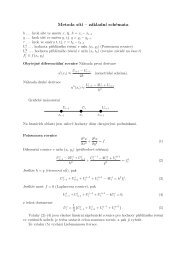
Let us assume that the photographed pattern creates a series of collinear<br />
points A, 1, 2, 3, …, O and B. Let us also assume that the standard was<br />
photographed so that the O’ point (the image of the point O) is in the<br />
distortion center and the images of A and B points are located in equal<br />
distance from the distortion center. Distortion for points A’ and B’ is<br />
identical, to simplify things, we may assume that it is equal to 0. The central<br />
projection is a projection transformation for a series of collinear points, it is<br />
determined through giving three points. Thus, knowing the location of<br />
points A’, O’ and B’ we may determine the real, without distortion, location<br />
of points 1’, 2’, 3’, … in the photograph.<br />
5 Practical determination of distortion<br />
coefficients<br />
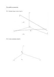
A pattern created by squares with 0,5 cm side was prepared and printed,<br />
making a grid – 180 cm long and 8 cm wide (Figure 2). The grid was<br />
photographed several times so that the picture of the longer lines of the<br />
pattern was placed along the photograph’s diagonal. Each photograph was<br />
rotated around the distortion center so that the adjacent (in relation to the<br />
distortion center) longer lines of the pattern were parallel to the longer side<br />
of the photograph. Then a horizontal straight line was drawn through the<br />
distortion center, then, with the use of appropriate graphic procedures, the<br />
intersection points between the straight lines and the shorter lines of the grid<br />
were determined and their distances from the distortion center were<br />
calculated. The picture where one of the points was located near the<br />
distortion center and two other – almost at the same distance from the<br />
distortion center – was selected for the further calculations. The selected<br />
points correspond to points A’, O’ and B’, respectively, of chapter …, the<br />
other to points 1’, 2’, 3’, … . Then, using the properties of the projection<br />
transformation, the real distances of points 1’, 2’, 3’, …, (points 1”, 2”, 3”,<br />
…) from the distortion center were calculated. In the end, using the Maple<br />
software, the approximation of the (A’, A’), (1’,1”), (2’, 2”), (3’, 3”), … ,<br />
(O’,O’) and (B’, B’) point sequence was made with the appropriate grade<br />
81