

HW manual - TG Drives
HW manual - TG Drives
HW manual - TG Drives

You also want an ePaper? Increase the reach of your titles
YUMPU automatically turns print PDFs into web optimized ePapers that Google loves.
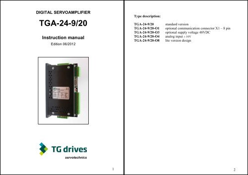
DIGITAL SERVOAMPLIFIER<br />
<strong>TG</strong>A-24-9/20<br />
Instruction <strong>manual</strong><br />
Edition 06/2012<br />
Type description:<br />
<strong>TG</strong>A-24-9/20<br />
<strong>TG</strong>A-24-9/20-O1<br />
<strong>TG</strong>A-24-9/20-O3<br />
<strong>TG</strong>A-24-9/20-O4<br />
<strong>TG</strong>A-24-9/20-O8<br />
standard version<br />
optional communication connector X1 – 8 pin<br />
optional supply voltage 48VDC<br />
analog input ± 10V<br />
lite version design<br />
servotechnics<br />
1<br />
2
Safety instructions<br />
• Read this documentation before carying out instalation. Incorrect handling of the<br />
servoamplifier can lead to personal injury or material damage.<br />
• The servoamplifier contain electrostatically sensitive components which may be<br />
damaged by incorrect handling. Ground yourself before touching the<br />
servoamplifier.<br />
• Do not open the units. Keep all cover and switchgear cabinet doors closed during<br />
operation.<br />
• Servoamplifiers may have hot cooling surfaces during operation.<br />
• Never undo the electrical connections to the servoamplifier while it is live. There<br />
is danger of electric arcing with damage to contacts.<br />
European directives and standards<br />
Servoamplifiers are components, which are intended to be incorporated into electrical<br />
plants and machines for industrial use.<br />
When the servoamplifiers are built into machines or plants, the intended operation of<br />
the amplifier is forbidden until it has been established that the machine or plant<br />
fulfills the requirements of the EC Directive on Machines 98/37/EC and the EC<br />
Directive on EMC (89/336/EEC).<br />
The manufacturer of of the machine or plant is responsible for ensuring that they<br />
meet the limits which are required by the EMC regulations.<br />
CE – conformance<br />
Conformance with the EC Directive on EMC 89/336/EEC is mandatory for the<br />
supply of servoamplifiers within the European Cummunity.<br />
The servoamplifiers <strong>TG</strong>A-24 have been tested by an authorized testing laboratory in a<br />
defined configuration with the system components which are described in this<br />
documentation. Any divergence from the configuration anf installation described in<br />
this documentation means that you will be responsible for the performance of new<br />
measurements to ensure that the regulatory requirements are met.<br />
Prescribed use of the servoamplifier<br />
The servoamplifiers are components which are built into electrical equipment or<br />
machines, and can only be used as integral components of such equipment.<br />
The servoamplifiers <strong>TG</strong>A-24 is only intended to drive with specific brushless<br />
synchronous servomotors, with closed-loop control of torque, speed and/or position.<br />
The servoamplifiers may only be operated in a closed switchgear cabinet, taking into<br />
account the ambient conditions in technical specification. Use only copper wire. Wire<br />
size may be determined from EN60204.<br />
We only guarantee the conformance of the servoamplifiers with the standards for<br />
industrial areas, if the components (motors, cables, amplifiers etc) are delivered by<br />
<strong>TG</strong> <strong>Drives</strong> s.r.o.<br />
Technical data<br />
Parameters<br />
Rated supply voltage V =<br />
Unit Data<br />
24 (15 - 42)<br />
option O3: 48<br />
Rated installed load for S1 operation W 230<br />
Rated output current A rms 9<br />
Peak output current (max. ca 5 s) A rms 18,5<br />
Overvoltage protection treshold (transil) V 47<br />
Dissipation at rated load W 20<br />
Fusing<br />
Supply 24 VDC – internal<br />
– external<br />
Inputs / outputs<br />
Analog input, resolution 12 bit<br />
Input resistance<br />
Digital inputs with adjustable function 24 VDC<br />
Digital outputs with adjustable function,<br />
24 VDC, PNP<br />
– T 10 A<br />
– C 8 A<br />
0 - 5<br />
V option O4: ±10<br />
kΩ 15<br />
qty 8<br />
V low 0 .. 5 / high 7 .. 30<br />
mA 6<br />
qty 4<br />
V max. 42<br />
mA 25<br />
Counter inputs for IRC or stepper-motor signals – 5V (RS422)<br />
Connectors<br />
Control signals – Interhart 3.81, 1.5mm 2<br />
Power – Interhart 5.08, 2.5mm 2<br />
Resolver input – Interhart 3.81, 1.5mm 2<br />
Communication –<br />
SubD 9-pole plug<br />
option O1 8-pole Interhart 3.81<br />
Mechanical<br />
Weight kg 0.6<br />
RoDimensions without connectors mm 157 × 86 × 40<br />
Environment<br />
Operating temperature °C 0 - 40<br />
Relative humidity % max. 85<br />
3<br />
4
Instalation<br />
Interfaces description<br />
Dimensions<br />
Material: 2 or 4 screws M4<br />
5<br />
6
Recommended connection diagram<br />
Resolver cable connection (X7)<br />
The resolver cable connection for<br />
<strong>TG</strong>T1,<strong>TG</strong>T2, <strong>TG</strong>T3,<strong>TG</strong>H2,<strong>TG</strong>H3<br />
servomotors with the cable glands<br />
The resolver cable connection for<br />
<strong>TG</strong>T1,<strong>TG</strong>T2, <strong>TG</strong>T3,<strong>TG</strong>H2,<strong>TG</strong>H3<br />
servomotors with the round<br />
connectors<br />
The resolver cable connection for<br />
<strong>TG</strong>H0 servomotors with the flying<br />
leads<br />
The ferrite rings use to decrease the<br />
electromagnetic noice.<br />
The unscreened ends of the cabels should<br />
be as short as possible.<br />
7<br />
8
Motor cable connection (X8)<br />
Motor cable connection for <strong>TG</strong>T1, <strong>TG</strong>T2, <strong>TG</strong>T3, <strong>TG</strong>H2 and <strong>TG</strong>H3 servomotors is<br />
described in the chapter Recommended connection diagram (page 7). For <strong>TG</strong>H0<br />
(only) with the flying leads is valid following motor connection:<br />
RS232 interface, PC connection (X1)<br />
The setting of the regulator parameters, inputs/outputs setting, position control and<br />
position profiles can be carried out with an ordinary commercial PC.<br />
Connect the PC interface (X1) of servoamplifier while the supply to the equipment is<br />
switched off via a normal commercial 3-core null-modem cable to a serial interface<br />
on the PC (see the diagrams below).<br />
CAN-BUS interface<br />
To meet ISO11898 you should use a bus cable<br />
with a characteristic impedance of 120 Ω.<br />
The maximum usable cable length for reliable communication<br />
decreases with increasing transmission speed.<br />
Cable length, depending on the transmission rate<br />
Transmission rate (kbaud) max. cable lngth (m)<br />
1 000 20<br />
500 70<br />
250 115<br />
For EMC reasons, the SubD connector housing must fulfill the following conditions:<br />
− metal or metalized housing<br />
− provision for cable shielding connection<br />
in housing, large-area connection<br />
9<br />
10
Connection to stepper-motor controller<br />
(X2)<br />
This interface can be used to connect the<br />
servoamplifier to a stepper-motor controller<br />
with 5V signal level. The value of R<br />
according to line impedance: 150Ω – 1kΩ.<br />
Interface for encoder input (X2)<br />
This interface can be used to operate<br />
the servoamplifier as a slave,<br />
mastered by an encoder with RS422<br />
signals level in gearing mode or by<br />
another servoamplifier (electronic<br />
gearing)<br />
Interface for encoder simulation<br />
(X2)<br />
This interface can be used to output<br />
incremental position value (RS422<br />
signals level) in all of the operation<br />
modes as feedback for the control<br />
system or as setpoint position in<br />
Master-Slave operation.<br />
<strong>TG</strong> <strong>Drives</strong>, s.r.o.<br />
Jeneweinova 37<br />
617 00 Brno<br />
Czech republic<br />
www.tgdrives.com<br />
info@tgdrives.cz<br />
phone: 00420 545 234 935<br />
fax: 00420 545 234 735<br />
11


