Data Sheet
Data Sheet
Data Sheet

You also want an ePaper? Increase the reach of your titles
YUMPU automatically turns print PDFs into web optimized ePapers that Google loves.
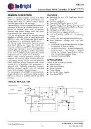
High Frequency PWM Controller With Short Circuit Restart<br />
FP5003<br />
General Description<br />
The FP5003, a high performance monolithic IC, includes adjustable frequency oscillator, error<br />
amplifier for pulse width modulation (PWM) control, 1.0V precision voltage reference, under-voltage<br />
lockout circuit (UVLO), variable pulse duty control (DTC) circuit and programmable auto-restart timer<br />
for short circuit shutdown protection (SCSAR). Built-in totem-pole transistors pair drives MOS directly<br />
at high frequency operation with high efficiency. It is very easy to design a DC-DC converter using a<br />
few external components. The typical application example is shown below:<br />
Features<br />
‣ Wide Operating Voltage Range:3.6~30V<br />
‣ Reference Voltage Precision: ±2%<br />
‣ Output Source / Sink Current up to 100mA<br />
‣ Totem-Pole Output for MOS Drive<br />
‣ Oscillator Frequency:Max.1.5MHz<br />
‣ Variable Duty Control (DTC)<br />
‣ Under Voltage Lockout Protection Function (UVLO)<br />
‣ Short Circuit Shutdown Protection / Auto Re-start Function (SCSAR)<br />
‣ Package:SOP-8L / MSOP-8L / SOP-8L (EP)<br />
Typical Application Circuit<br />
V IN<br />
V OUT<br />
OUT<br />
VCC<br />
RT 7<br />
FB<br />
5<br />
SCP<br />
FP5003<br />
6<br />
DTC<br />
8<br />
GND<br />
3<br />
COMP<br />
This datasheet contains new product information. Feeling Technology reserves the rights to modify the product specification without notice.<br />
No liability is assumed as a result of the use of this product. No rights under any patent accompany the sales of the product.<br />
Website: http://www.feeling-tech.com.tw Rev. 0.9<br />
1/19
FP5003<br />
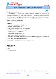
Function Block Diagram<br />
VCC<br />
RT<br />
DTC<br />
OUT<br />
UVLO<br />
1V<br />
Reference<br />
Voltage<br />
2.5V<br />
IDT<br />
1.5V<br />
ITH<br />
OSC<br />
PWM / DTC<br />
COMP<br />
Error<br />
AMP<br />
SCP<br />
COMP 1<br />
FB<br />
COMP<br />
SCSAR<br />
SCP COMP<br />
&<br />
RE-START<br />
Circuits<br />
GND<br />
This datasheet contains new product information. Feeling Technology reserves the rights to modify the product specification without notice.<br />
No liability is assumed as a result of the use of this product. No rights under any patent accompany the sales of the product.<br />
Website: http://www.feeling-tech.com.tw Rev. 0.9<br />
2/19
FP5003<br />
Pin Descriptions<br />
SOP-8L<br />
Name No. I / O Description<br />
OUT 1 O Totem-pole Transistor Pair Output<br />
V CC 2 P IC Power Supply<br />
COMP 3 O Error Amplifier Feedback Output<br />
FB 4 I Error Amplifier Inverting Input<br />
SCSAR 5 I Short Circuit Protection Input<br />
SOP-8L (EP)<br />
DTC 6 I Duty Control Input<br />
RT 7 I<br />
Frequency Adjustment. Connect a Resistor<br />
Between This Pin and GND to Adjust PWM<br />
Frequency<br />
GND 8 P IC Ground<br />
Name No. I / O Description<br />
OUT 1 O Totem-pole Transistor Pair Output<br />
V CC 2 P IC Power Supply<br />
COMP 3 O Error Amplifier Feedback Output<br />
FB 4 I Error Amplifier Inverting Input<br />
SCSAR 5 I Short Circuit Protection Input<br />
DTC 6 I Dead-Time Control Input<br />
RT 7 I<br />
Frequency Adjustment. Connect a Resistor<br />
Between This Pin and GND to Adjust PWM<br />
Frequency<br />
GND 8 P IC Ground<br />
EP 9 P Exposed PAD. Must connect to GND<br />
MSOP-8L<br />
Name No. I / O Description<br />
OUT 1 O Totem-pole Transistor Pair Output<br />
V CC 2 P IC Power Supply<br />
COMP 3 O Error Amplifier Feedback Output<br />
FB 4 I Error Amplifier Inverting Input<br />
SCSAR 5 I Short Circuit Protection Input<br />
DTC 6 I Dead-Time Control Input<br />
RT 7 I<br />
Frequency Adjustment. Connect a Resistor<br />
Between This Pin and GND to Adjust PWM<br />
Frequency<br />
GND 8 P IC Ground<br />
This datasheet contains new product information. Feeling Technology reserves the rights to modify the product specification without notice.<br />
No liability is assumed as a result of the use of this product. No rights under any patent accompany the sales of the product.<br />
Website: http://www.feeling-tech.com.tw Rev. 0.9<br />
3/19
FP5003<br />
Marking Information<br />
SOP-8L & SOP-8L (EP)<br />
FP5003<br />
-<br />
Halogen Free<br />
Lot Number<br />
Internal ID<br />
Per-Half Month<br />
Year<br />
MSOP-8L<br />
FP5003<br />
9Fa-86L<br />
Halogen Free<br />
Lot Number<br />
Internal ID<br />
Per-Half Month<br />
Year<br />
Halogen Free: Halogen free product indicator<br />
Lot Number: Wafer lot number’s last two digits<br />
For Example: 132386TB 86<br />
Internal ID: Internal Identification Code n<br />
Per-Half Month: Production period indicated in half month time unit<br />
For Example: January → A (Front Half Month), B (Last Half Month)<br />
Year: Production year’s last digit<br />
February → C (Front Half Month), D(Last Half Month)<br />
This datasheet contains new product information. Feeling Technology reserves the rights to modify the product specification without notice.<br />
No liability is assumed as a result of the use of this product. No rights under any patent accompany the sales of the product.<br />
Website: http://www.feeling-tech.com.tw Rev. 0.9<br />
4/19
FP5003<br />
Ordering Information<br />
Part Number Operating Temperature Package MOQ Description<br />
FP5003DR-LF -20°C ~ +105°C SOP-8L 2500EA Tape & Reel<br />
FP5003XR-LF -20°C ~ +105°C SOP-8L (EP) 2500EA Tape & Reel<br />
FP5003TR-LF -20°C ~ +105°C MSOP-8L 2500EA Tape & Reel<br />
Absolute Maximum Ratings<br />
Parameter Symbol Conditions Min. Typ. Max. Unit<br />
Power Supply Voltage V CC 30 V<br />
Output Voltage V o 30 V<br />
Source / Sink Output Current I O ±150 mA<br />
Junction Temperature T j +150 ℃<br />
SOP-8L (T A ≤ 25℃) 570 mW<br />
Allowable Dissipation<br />
SOP-8L (EP) (T A ≤ 25℃) 600 mW<br />
MSOP-8L (T A ≤ 25℃) 400 mW<br />
Thermal Resistance<br />
Thermal Resistance<br />
Thermal Resistance<br />
T JA +130<br />
SOP-8L<br />
℃ / W<br />
+38.8 ℃ / W<br />
T JC<br />
T JA<br />
SOP-8L (EP)<br />
+120 ℃ / W<br />
+38.8 ℃ / W<br />
T JC<br />
T JA +260<br />
MSOP-8L<br />
℃ / W<br />
+60 ℃ / W<br />
T JC<br />
Operating Temperature Range -20 +105 ℃<br />
Storage Temperature Range -65 +150 ℃<br />
Lead Temperature (soldering, 10<br />
sec)<br />
+260 ℃<br />
IR Re-flow Soldering Curve<br />
This datasheet contains new product information. Feeling Technology reserves the rights to modify the product specification without notice.<br />
No liability is assumed as a result of the use of this product. No rights under any patent accompany the sales of the product.<br />
Website: http://www.feeling-tech.com.tw Rev. 0.9<br />
5/19
FP5003<br />
Recommended Operating Conditions<br />
Parameter Symbol Conditions Min. Typ. Max. Unit<br />
Supply Voltage V CC 3.6 30 V<br />
Operating Temperature -20 +105 °C<br />
DC Electrical Characteristics (V CC = 6V, T A =25°C, unless otherwise specified)<br />
Parameter Symbol Conditions Min. Typ. Max. Unit<br />
Reference<br />
Output Voltage V REF COMP Connected to FB 0.98 1 1.02 V<br />
Input Regulation<br />
△V<br />
REF V CC =3.6 V to 30 V 2 12.5 mV<br />
Output Voltage Change with<br />
△V<br />
REF /<br />
T A =-20℃ to 25℃ -10 -1 15 mV / V<br />
Temperature<br />
V REF T A = 25℃ to 85℃ -10 -2 10 mV / V<br />
Under Voltage Lockout<br />
Upper Threshold Voltage V UPPER 3 V<br />
Lower Threshold Voltage V LOW 2.8 V<br />
Hysteresis V HYS 100 200 mV<br />
Short-Circuit Protection<br />
SCP Standby Voltage V SB V COMP 1.5V 0.7 V<br />
SCP re-start Charge Current I RSC V COMP >1.5V 20 μA<br />
SCP re-start / Hold Time T RS / T HOLD V COMP >1.5V 1 / 32 Ratio<br />
SCP Comparator 1 Threshold<br />
Voltage<br />
V COMP (TH) 1.5 V<br />
Oscillator<br />
Frequency f R T =100K 260 KHz<br />
Standard Deviation of Frequency<br />
Frequency Change with Voltage<br />
△ f<br />
15 KHz<br />
△ f / △V<br />
V CC =3.6V to 30V 1 KHz<br />
Frequency Change with<br />
Temperature<br />
△ f / △T<br />
T A =-20℃ to 25℃ ±1 %<br />
T A = 25℃ to 105℃ ±1 %<br />
Voltage at RT V RT 1 V<br />
This datasheet contains new product information. Feeling Technology reserves the rights to modify the product specification without notice.<br />
No liability is assumed as a result of the use of this product. No rights under any patent accompany the sales of the product.<br />
Website: http://www.feeling-tech.com.tw Rev. 0.9<br />
6/19
FP5003<br />
DC Electrical Characteristics (Continued)<br />
Parameter Symbol Conditions Min. Typ. Max. Unit<br />
Duty-time Control<br />
Output (Source) Current I SOURCE V (DT) =1.5V 0.9×I RT 1.2×I RT V<br />
Input Threshold Voltage<br />
Error Amplifier<br />
V TH<br />
Duty Cycle=0% 0.5 0.7 V<br />
Duty Cycle=100% 1.3 1.5 V<br />
Input Voltage V IN V CC =3.6V to 30V 0 1.5 V<br />
Input Bias Current I BIAS -160 -500 nA<br />
Output Voltage Swing Positive V POS 1.5 2.3 V<br />
Output Voltage Swing Negative V NEG 0.3 0.4 V<br />
Open-loop Voltage Amplification A VO 80 dB<br />
Unity-Gain Bandwidth BW U 1.5 MHz<br />
Output (Sink) Current I SINK V I (FB) =1.2V, COMP=1V 600 800 μA<br />
Output (Source) Current I SOURCE V I (FB) =0.8V, COMP=1V -100 -150 μA<br />
Output<br />
Output Low Voltage V OL Io=100mA 1.7 V<br />
Output High Voltage V OH Io=100mA 4.4 V<br />
Total Device<br />
Standby Supply Current Off State I STANDBY 3.5 4.0 mA<br />
Average Supply Current I AVE R T =100k 3.8 5 mA<br />
This datasheet contains new product information. Feeling Technology reserves the rights to modify the product specification without notice.<br />
No liability is assumed as a result of the use of this product. No rights under any patent accompany the sales of the product.<br />
Website: http://www.feeling-tech.com.tw Rev. 0.9<br />
7/19
FP5003<br />
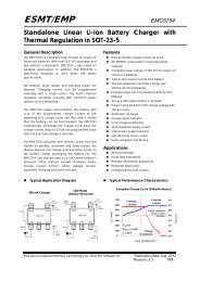
Typical Characteristics<br />
2M<br />
OSCILLATOR FREQUENCY<br />
VS<br />
TIMING RESISTANCE<br />
Vcc = 6 V<br />
TA =25 o C<br />
400<br />
350<br />
OSCILLATOR FREQUENCY<br />
VS<br />
AMBIENT TEMPERATURE<br />
Vcc = 6V<br />
Rt =100 kΩ<br />
fosc - Oscillator Frequency - Hz<br />
1M<br />
fosc - Oscillator Frequency - kHz<br />
300<br />
250<br />
200<br />
150<br />
10 0 K<br />
10 K 100 K 1 M<br />
100<br />
-50 -25 0 25 50 75 100<br />
Rt - Timing Resistance -Ω<br />
T A - Ambient Temperature - ℃<br />
Figure 1 Figure 2<br />
1.6<br />
REFERENCE OUTPUT VOLTAGE<br />
VS<br />
POWER-SUPPLY VOLTAGE<br />
1.25<br />
REFERENCE OUTPUT VOLTAGE<br />
VS<br />
AMBIENT TEMPERATURE<br />
Vref - Reference Output Voltage - V<br />
TA =25 o C<br />
1.4 FB and COMP<br />
Connected Together<br />
1.2<br />
1.0<br />
0.8<br />
0.6<br />
0.4<br />
Vref - Reference Output Voltage - V<br />
1.2<br />
1.15<br />
1.1<br />
1.05<br />
1.0<br />
0.95<br />
0.9<br />
Vcc = 6V<br />
FB and COMP<br />
Connected Together<br />
0.2<br />
0.85<br />
0<br />
0 1 2 3 4 5 6<br />
7 8 9 10<br />
0.8<br />
- 50 - 25 0 25 50 75 100<br />
Vcc - Power Supply Voltage - V<br />
TA- Ambient Temperature - ℃<br />
Figure 3 Figure 4<br />
3.6<br />
AVERAGE SUPPLY CURRENT<br />
T =25 o C<br />
R A t =100KΩ<br />
VS<br />
POWER-SUPPLY VOLTAGE<br />
5.5<br />
5.0<br />
AVERAGE SUPPLY CURRENT<br />
VS<br />
AMBIENT TEMPERATURE<br />
Vcc = 6V<br />
Rt =100kΩ<br />
Icc - Average Supply Current - mA<br />
3.4<br />
3.2<br />
3.0<br />
Icc - Average Supply Current - mA<br />
4.5<br />
4.0<br />
3.5<br />
3.0<br />
0<br />
0 10<br />
15<br />
20<br />
25<br />
30<br />
0<br />
-50 -25 0 25 50 75 100<br />
Vcc - Power-Supply Voltage - V<br />
TA- Ambient Temperature - ℃<br />
Figure 5 Figure 6<br />
This datasheet contains new product information. Feeling Technology reserves the rights to modify the product specification without notice.<br />
No liability is assumed as a result of the use of this product. No rights under any patent accompany the sales of the product.<br />
Website: http://www.feeling-tech.com.tw Rev. 0.9<br />
8/19
FP5003<br />
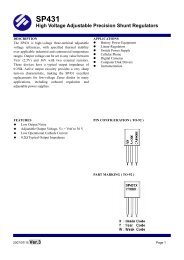
PWM Triangle Wave Amplitude Voltage - V<br />
1.8<br />
1.5<br />
1.2<br />
0.9<br />
0.6<br />
0.3<br />
PWM TRIANGLE WAVE AMPLITUDE<br />
VOLTAGE<br />
VS<br />
OSCILLATOR FREQUENCY<br />
Vcc = 6 V<br />
TA = 25 o C<br />
Voscmax (100% duty cycle)<br />
Vosc<br />
min (zero duty cycle)<br />
Output Duty Cycle - %<br />
120<br />
100<br />
80<br />
60<br />
40<br />
20<br />
Vcc = 6V<br />
TA = 25 o C<br />
Rt =100kΩ<br />
OUTPUT DUTY CYCLE<br />
VS<br />
DTC VOLTAGE<br />
0<br />
10 K 100 K 1M 10 M<br />
0<br />
0 0.5 1 1.5<br />
2<br />
fosc - Oscillator Frequency - Hz<br />
DTC Voltage - V<br />
Figure 7<br />
Figure 8<br />
0.34<br />
ERROR AMPLIFIER OUTPUT VOLTAGE<br />
VS<br />
AMBIENT TEMPERATURE<br />
2.60<br />
ERROR AMPLIFIER OUTPUT VOLTAGE<br />
VS<br />
AMBIENT TEMPERATURE<br />
Vo - Error Amplifier Output Voltage - mV<br />
0.32<br />
0.30<br />
0.28<br />
0.26<br />
0.24<br />
0.22<br />
Vcc = 6V<br />
VI(FB) = 1.2 V<br />
No Load<br />
Vo - Error Amplifier Output Voltage - V<br />
2.55<br />
2.50<br />
2.45<br />
2.40<br />
2.35<br />
2.30<br />
2.25<br />
Vcc = 6V<br />
VI(FB) = 0.8 V<br />
No Load<br />
0.20<br />
- 25 - 20 25 50 75 100 125<br />
TA - Ambient Temperature - ℃<br />
Figure 9<br />
2.20<br />
- 25 - 20 25 50 75 100 125<br />
TA - Ambient Temperature - ℃<br />
Figure 10<br />
Vce - Output Saturation Voltage - V<br />
2.2<br />
1.8<br />
1.4<br />
1.0<br />
0.6<br />
0.2<br />
OUTPUT SATURATION VOLTAGE<br />
VS<br />
OUTPUT (SINK) CURRENT<br />
Vcc = 6V<br />
TA = 25 o C<br />
Vce - Output Saturation Voltage - V<br />
5.2<br />
5.0<br />
4.8<br />
4.6<br />
4.4<br />
4.2<br />
OUTPUT SATURATION VOLTAGE<br />
VS<br />
OUTPUT (SOURCE) CURRENT<br />
Vcc = 6V<br />
TA = 25 o C<br />
0<br />
0 20 40 60 80 100<br />
Io - Output (Sink) Current - mA<br />
Figure 11<br />
0<br />
0 20 40 60 80 100<br />
Io - Output (Source) Current - mA<br />
Figure 12<br />
This datasheet contains new product information. Feeling Technology reserves the rights to modify the product specification without notice.<br />
No liability is assumed as a result of the use of this product. No rights under any patent accompany the sales of the product.<br />
Website: http://www.feeling-tech.com.tw Rev. 0.9<br />
9/19
FP5003<br />
Function Description<br />
Voltage Reference<br />
The FP5003 includes a 2.5V reference regulator to supply its own internal circuits. Also, a<br />
resistive divider is included to divide the 2.5V reference voltage to 1.0V as the precision reference<br />
voltage for the error amplifier's non-inverting terminal and SCP comparator's 1.0V threshold voltage.<br />
Error Amplifier<br />
The error amplifier compares the feedback voltage, divided from DC-DC converter output, with<br />
the 1.0V reference and generates the error signal for the PWM comparator. The relation between V OUT<br />
and V REF are shown below (see Figure 13).<br />
V<br />
R1 1<br />
<br />
R2 <br />
OUT V REF<br />
Compensation<br />
Network<br />
3<br />
COMP<br />
V OUT<br />
R1<br />
R2<br />
4<br />
FB<br />
To PWM<br />
Comparator<br />
8<br />
GND<br />
V REF = 1.0 V<br />
FP5003<br />
Figure 13. Error Amplifier with Converter Feedback Resistors<br />
Note:<br />
It is necessary to check the converter total open loop gain and phase shift from Bode plot before<br />
compensation network adjustment. Finally, let the system works stability.<br />
This datasheet contains new product information. Feeling Technology reserves the rights to modify the product specification without notice.<br />
No liability is assumed as a result of the use of this product. No rights under any patent accompany the sales of the product.<br />
Website: http://www.feeling-tech.com.tw Rev. 0.9<br />
10/19
FP5003<br />
Oscillator / PWM Comparator<br />
The oscillator frequency (fosc) can be adjusted from 20KHz to 1.5MHz by the resistor connected<br />
to R T pin. The relation between the oscillator frequency and R T value can be determined by the graph<br />
shown in Figure 1.<br />
The internal oscillator output is a triangular waveform. Its minimum and maximum voltage levels<br />
are approximately 0.7V and 1.3V respectively (see Figure 14). The PWM comparator compares the<br />
triangular waveform with the signals from output voltage of error-amplifier and the DTC voltage. The<br />
PWM comparator output controls the output stage of totem-pole transistors pair off or on whenever the<br />
triangular wave is greater than the both input signals or less.<br />
COMP<br />
DTC<br />
OSC<br />
1.5 V<br />
PWM<br />
COMPARATOR<br />
TOTEM-POLE<br />
OUTPUT<br />
V CC<br />
3.0 V<br />
SCSAR<br />
V TH<br />
Charge<br />
Current<br />
Hold-stage<br />
Standby stage<br />
Re-start<br />
stage<br />
Figure 14. PWM Timing Diagram<br />
This datasheet contains new product information. Feeling Technology reserves the rights to modify the product specification without notice.<br />
No liability is assumed as a result of the use of this product. No rights under any patent accompany the sales of the product.<br />
Website: http://www.feeling-tech.com.tw Rev. 0.9<br />
11/19
FP5003<br />
Duty Control (DTC)<br />
DTC main function is to limit PWM duty cycle to less than 100%. The source current of duty<br />
control current I DT at DTC pin is the same as the one of R T . The source current I DT flows through a<br />
resistor R DT , connecting between DTC pin and GND, generating a bias voltage V DT . This V DT voltage is<br />
further compared with the output waveform of oscillator in the PWM comparator. The PWM duty cycle<br />
begins from 0% when V DT sets at 0.7V or less, and 100% when V DT sets at 1.3V or greater. Engineer<br />
can choose a resistor R DT for a specific limitation of PWM duty cycle D. According to the following<br />
equation, we can choose a R DT for a maximum duty cycle.<br />
R<br />
DT<br />
<br />
R<br />
1250<br />
0.6<br />
D<br />
0.7<br />
T<br />
For example:<br />
R T is 33KΩ for oscillator frequency, and we assume the allowable maximum duty cycle is 75%.<br />
R DT = (33K+1250) x (0.6x0.75+0.7) = 39.38K<br />
When a 39.38KΩ resistor is used as R DT , the maximum limitation of PWM duty cycle is 75%.<br />
A capacitor (C DT ), parallel connecting with the resistor R DT as shown in Figure 15, is used to<br />
implement the soft-start function during power on. The soft-start time equation is:<br />
V<br />
DT<br />
I<br />
DT<br />
R<br />
DT<br />
<br />
<br />
1<br />
e<br />
<br />
t<br />
R DT C DT<br />
<br />
<br />
<br />
<br />
I DT<br />
2.5V<br />
6<br />
DTC<br />
V DT<br />
From Error Amplifier<br />
PWM<br />
COMP<br />
C DT<br />
R DT<br />
OSC<br />
FP5003<br />
Figure 15. Soft-Start Circuit<br />
Note:<br />
C DT is discharged by internal circuit every time when UVLO or SCP becomes active.<br />
This datasheet contains new product information. Feeling Technology reserves the rights to modify the product specification without notice.<br />
No liability is assumed as a result of the use of this product. No rights under any patent accompany the sales of the product.<br />
Website: http://www.feeling-tech.com.tw Rev. 0.9<br />
12/19
FP5003<br />
Under Voltage Lock-out (UVLO) Protection<br />
When the power supply turns off, the output of FP5003 also turns off and resets the SCP latch<br />
whenever the supply voltage drops under the UVLO off threshold voltage. It is a simple protection<br />
function when the supply voltage can not maintain at a stable operating condition. The UVLO<br />
hysteresis voltage avoids an internal false trigger whenever power noises or spikes appear.<br />
Short-circuit Shutdown and Auto Re-start Protection (SCSAR)<br />
FP5003 includes short-circuit shutdown and auto re-start protection function (see Figure 16),<br />
which turns the power MOS off to prevent damage when the converter output is over loading or short<br />
circuit.<br />
2.5 V<br />
Icharge<br />
Icharge<br />
2<br />
Idischarge<br />
SCP<br />
COMP3<br />
1.4V<br />
Cscp<br />
5<br />
SCSAR<br />
From Error<br />
Amp<br />
1.5 V<br />
SCP<br />
COMP1<br />
Q1<br />
V<br />
SCP<br />
COMP2<br />
Q3<br />
0.7V/0.2V<br />
Low High<br />
Q<br />
S<br />
R<br />
To Output<br />
Drive Logic<br />
To DTC<br />
PWM<br />
Comparator<br />
Q2<br />
Figure 16. SCSAR Protection Circuit<br />
When error amplifier output voltage is lower than 1.5V, SCP comparator 1 output will keep in<br />
high state, Q1 is turn-on, and C SCP can not be charged. When short circuit occurs, the COMP pin of<br />
error-amplifier would rise to larger than 1.5V. SCP comparator 1 output changes to low state and C SCP<br />
is charged by I CHARGE current. Once C SCP is charged to higher than 0.7V threshold, SCP comparator 2<br />
output will change to high state and Q2 is turned-on to keep Q1 off in latch mode. Meanwhile, the<br />
source current of C SCP would change to half of original current for the first shutdown phase that will turn<br />
FP5003's output off and pull DTC pin to low. The SCP function of FP5003 is released if short circuit<br />
condition is removed before SCP comparator 2 outputs and turning on Q2.<br />
When C SCP voltage is greater than 1.4V of SCP comparator 3, the output of S-R Latch would<br />
turn on Q3 and change SCP comparator 2's output from 0.7V to 0.2V. When SCP comparator 3 is<br />
active, C SCP is discharged until SCP comparator 2 is released from the latch state, output of FP5003 is<br />
This datasheet contains new product information. Feeling Technology reserves the rights to modify the product specification without notice.<br />
No liability is assumed as a result of the use of this product. No rights under any patent accompany the sales of the product.<br />
Website: http://www.feeling-tech.com.tw Rev. 0.9<br />
13/19
FP5003<br />
active and DTC pin is working in soft-start state or limitation of duty cycle. C SCP discharging time from<br />
1.4V to 0.2V is the second shutdown phase. After this phase, FP5003 would be released from<br />
shutdown state and re-start the normal operation. Figure 17 is a relation description about SCSAR pin<br />
and the other pins of FP5003.<br />
SCP Comparator 1 Threshold Voltage<br />
Short Circuit<br />
Occured<br />
1.5V<br />
COMP<br />
V TH2<br />
1.4V<br />
V TH1<br />
VCSCP<br />
I TH1<br />
I TH2<br />
0.7V<br />
I TH3<br />
V TH3<br />
0.2V<br />
OUT<br />
DTC<br />
V CC 3.0V<br />
NORMAL OPERATION<br />
SHUTDOWN<br />
PHASE1 PHASE2<br />
RE-START<br />
Figure 17. Shutdown and Re-start waveform<br />
The equations are shown below for shutdown and re-start time calculation:<br />
AUTO RE-START time equation:<br />
t<br />
RE<br />
START<br />
<br />
V<br />
TH1<br />
C<br />
I<br />
TH1<br />
SHUTDOWN time equation:<br />
t<br />
SHUTDOWN<br />
t<br />
PHASE1<br />
SCP<br />
t<br />
PHASE2<br />
<br />
V<br />
V <br />
C V<br />
V <br />
TH2<br />
I<br />
TH1<br />
TH2<br />
SCP<br />
<br />
TH2<br />
I<br />
TH3<br />
TH3<br />
C<br />
SCP<br />
This datasheet contains new product information. Feeling Technology reserves the rights to modify the product specification without notice.<br />
No liability is assumed as a result of the use of this product. No rights under any patent accompany the sales of the product.<br />
Website: http://www.feeling-tech.com.tw Rev. 0.9<br />
14/19
FP5003<br />
Output Transistors<br />
The output of the FP5003 is a totem-pole transistor pair, which provides current source and sink<br />
capability for driving the external MOSFET directly. A basic drive method is shown in figure 18.<br />
When PWM operation frequency is different, the both of on and off time of MOSFET also are<br />
different.<br />
I SOURCE<br />
OSC<br />
C<br />
EA<br />
DTC<br />
PWM<br />
COMP<br />
I SINK<br />
1<br />
R<br />
SCP<br />
Control<br />
Circuit<br />
FP5003<br />
Figure 18. MOSFET Output Driving Cricuit<br />
Note:<br />
It is very important to choose a suitable MOSFET for high frequency operation. The larger<br />
capacitance between gate and source of MOSFET makes more switching loss under the same<br />
condition such as high frequency operation, supply voltage and driving current.<br />
This datasheet contains new product information. Feeling Technology reserves the rights to modify the product specification without notice.<br />
No liability is assumed as a result of the use of this product. No rights under any patent accompany the sales of the product.<br />
Website: http://www.feeling-tech.com.tw Rev. 0.9<br />
15/19
FP5003<br />
Typical Application<br />
Application Example: V IN = DC 5.0V~ 24.0V<br />
V OUT = DC 3.3V, I OUT = 2.0A<br />
Vin<br />
+ C1<br />
100uF /35V<br />
C2<br />
0.1uF<br />
R1 10<br />
Q1<br />
COMP<br />
IC1<br />
1<br />
OUT GND<br />
8<br />
2<br />
VCC RT<br />
3<br />
COMP DTC<br />
7<br />
6<br />
4 5<br />
FB SCP<br />
SCP<br />
RT<br />
DTC<br />
L1<br />
D1<br />
SCD24<br />
20uH<br />
L2 4.7uH<br />
+3.3V<br />
+ C8<br />
100uF/6.3V<br />
Vout<br />
+ C9<br />
47uF/6.3V<br />
C5<br />
102<br />
C6<br />
303<br />
R6<br />
6.8K<br />
FP5003<br />
+ C4<br />
3.3uF<br />
R3<br />
56K<br />
C3<br />
0.1uF<br />
R2<br />
43K<br />
FB<br />
R5 12K 1%<br />
R4<br />
5.1K 1%<br />
R7<br />
2K<br />
C7<br />
103<br />
Note:<br />
This is a basic circuit of FP5003 example. C4 is a short circuit and re-start timing capacitor<br />
(C SCP ). The purpose of R3 and C3 is soft-start duty control (R DTC *C DTC ). R2 is for adjustable oscillator<br />
frequency (R T ). R5 and R4 are feedback bias resistors for V OUT . C5-R6-C6 establish compensation<br />
network for close loop stability.<br />
This datasheet contains new product information. Feeling Technology reserves the rights to modify the product specification without notice.<br />
No liability is assumed as a result of the use of this product. No rights under any patent accompany the sales of the product.<br />
Website: http://www.feeling-tech.com.tw Rev. 0.9<br />
16/19
FP5003<br />
Package Outline<br />
SOP-8L<br />
UNIT: mm<br />
Symbols Min. (mm) Max. (mm)<br />
A 1.346 1.752<br />
A1 0.101 0.254<br />
A2 1.498<br />
D 4.800 4.978<br />
E 3.810 3.987<br />
H 5.791 6.197<br />
L 0.406 1.270<br />
θ° 0° 8°<br />
Note:<br />
1. Package dimensions are in compliance with JEDEC outline: MS-012 AA.<br />
2. Dimension “D” does not include molding flash, protrusions or gate burrs.<br />
3. Dimension “E” does not include inter-lead flash or protrusions.<br />
This datasheet contains new product information. Feeling Technology reserves the rights to modify the product specification without notice.<br />
No liability is assumed as a result of the use of this product. No rights under any patent accompany the sales of the product.<br />
Website: http://www.feeling-tech.com.tw Rev. 0.9<br />
17/19
FP5003<br />
SOP-8L (EP)<br />
UNIT: mm<br />
Symbols Min. (mm) Max. (mm)<br />
A 1.346 1.752<br />
A1 0.050 0.152<br />
A2 1.498<br />
D 4.800 4.978<br />
E 3.810 3.987<br />
H 5.791 6.197<br />
L 0.406 1.270<br />
θ° 0° 8°<br />
Exposed PAD Dimensions:<br />
Symbols Min. (mm) Max. (mm)<br />
E1<br />
D1<br />
2.184 REF<br />
2.971 REF<br />
Note:<br />
1. Package dimensions are in compliance with JEDEC outline: MO-178 AA.<br />
2. Dimension ”D” does not include molding flash, protrusions or gate burrs.<br />
3. Dimension “E” does not include inter-lead flash or protrusions.<br />
This datasheet contains new product information. Feeling Technology reserves the rights to modify the product specification without notice.<br />
No liability is assumed as a result of the use of this product. No rights under any patent accompany the sales of the product.<br />
Website: http://www.feeling-tech.com.tw Rev. 0.9<br />
18/19
FP5003<br />
MSOP-8L<br />
UNIT: mm<br />
Symbols Min. (mm) Max. (mm)<br />
A 1.100<br />
A1 0.000 0.150<br />
A2 0.750 0.950<br />
D<br />
E<br />
E1<br />
3.000 BSC<br />
4.900 BSC<br />
3.000 BSC<br />
L 0.400 0.800<br />
L1<br />
0.950 REF<br />
θ° 0° 8°<br />
Notes:<br />
1. Package dimensions are in compliance with JEDEC outline: MO-187 AA.<br />
2. Dimension “D” does not include molding flash, protrusions or gate burrs.<br />
3. Dimension “E1” does not include inter-lead flash or protrusions.<br />
This datasheet contains new product information. Feeling Technology reserves the rights to modify the product specification without notice.<br />
No liability is assumed as a result of the use of this product. No rights under any patent accompany the sales of the product.<br />
Website: http://www.feeling-tech.com.tw Rev. 0.9<br />
19/19