M E C H A N I C A L C O M P O N E N T S
M E C H A N I C A L C O M P O N E N T S
M E C H A N I C A L C O M P O N E N T S

Create successful ePaper yourself
Turn your PDF publications into a flip-book with our unique Google optimized e-Paper software.
M E C H A N I C A L C O M P O N E N T S<br />
www.DanaherMotion.com • 815-226-2222<br />
94
M E C H A N I C A L C O M P O N E N T S<br />
INTRODUCTION<br />
SCREWS, ACTUATORS, STAGES<br />
If you're in the need of linear motion components or positioning systems, you've come to the<br />
right place. In the pages of this catalog, you will find a sampling of one of the most<br />
comprehensive ranges of electric linear actuators, mechanical positioning stages, ball screws,<br />
lead screws and rotary positioning systems available from any manufacturer in the world.<br />
ELECTRIC CYLINDERS<br />
Primarily designed to apply a force through an extendable rod, applications for IDC Electric<br />
Cylinders have gone from being a clean and efficient replacement for hydraulic actuators and<br />
pneumatic cylinders to becoming a common alternative to many types of linear<br />
transmissions. A wide variety of mounting and coupling alternatives significantly increases<br />
the problem solving potential of IDC Electric Cylinders.<br />
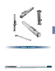
RODLESS ACTUATORS<br />
Need more load carrying capability Long travel, quiet operation and high moment loading<br />
differentiates IDC Rodless Actuators from other mechanical transmissions. The dichotomy of<br />
the high-force screw drive option and the high-speed belt option makes these products and<br />
ideal solution in many applications.<br />
CARTESIAN SYSTEMS<br />
Let Danaher Motion's experts completely design and, if you wish, assemble a multi-axis<br />
electromechanical system for you. IDC Cartesian systems are made by combining our<br />
moderate and heavy-duty actuators into 2 and 3-axis linear motion systems covering over<br />
6048 square inches of work area. Put our engineers and technicians to work for you.<br />
POSITIONING STAGES<br />
IDC's family of positioning stages work best where accurate and repeatable motion is critical.<br />
IDC offers a wide variety of single and multi-axis configurations, open and closed frame<br />
stages, ball screw, lead screw or linear motor driven and overhung and constant-support<br />
geometry configurations.<br />
ROTARY TABLES<br />
IDC rotary tables provide high rotary positioning repeatability and accuracy in driven and<br />
direct-drive models.<br />
BALL SCREW ASSEMBLIES<br />
For maximum precision and minimum friction, BS&A ball screw assemblies provide a wide<br />
range of available linear motion options. With many ball nut mounting configurations and<br />
screw precision grades, BS&A offers a ball screw that's right for your needs.<br />
LEAD SCREW ASSEMBLIES<br />
Rolled Acme lead screws are an excellent, economical means of accomplishing linear motion<br />
in many applications. For over 15 years, Ball Screws and Actuators has manufactured the<br />
highest quality lead screw assemblies. Our precision rolling machines ensure accurate<br />
positioning to 0.003 in/ft and our PTFE coating process produces assemblies that have less<br />
drag torque and last longer.<br />
Ball Screws and Actuators provides a large array of standard plastic nut assemblies in antibacklash<br />
or standard Supernut designs. For significantly higher loads, standard bronze nuts<br />
are available.<br />
www.DanaherMotion.com • 815-226-2222<br />
With the introduction of our new patent pending Zero-Backlash designs, BS&A provides<br />
assemblies with high axial stiffness, zero backlash and the absolute minimum drag torque to<br />
reduce motor requirements. These designs produce nuts that cost less, perform better and<br />
last longer. Both automatically adjust for wear, insuring zero backlash for the life of the nut.<br />
95<br />
Solutions by
M E C H A N I C A L C O M P O N E N T S<br />
IDC SELECTION OVERVIEW<br />
ACTUATORS, STAGES<br />
www.DanaherMotion.com • 815-226-2222<br />
Product Description<br />
Electric Cylinder Highest Force (Thrust) 1300<br />
Rod Type Clean, Hydraulic Replacement (51.3)<br />
Compact Cross Section<br />
SEE PAGE 98<br />
Extends into Work Area<br />
Rodless Actuators Highest Force (Thrust) 1000<br />
Screw Drive High Repeatability (40)<br />
Long Travel<br />
SEE PAGE 99<br />
Load Carrying Capability<br />
Rodless Actuators Very High Speed 3000<br />
Belt Drive Quiet Operation (120)<br />
Long Travel<br />
SEE PAGE 99<br />
Load Carrying Capability<br />
Cartesian Systems Fully Engineered Multi-Axis Systems 3000<br />
Complete 2 & 3 Axis Assemblies Large Work Area – 60x108 inches (120)<br />
Multiple & Custom Configurations<br />
SEE PAGES 100-101<br />
Long Travel<br />
Positioning Stages Smoothest Motion 1300<br />
High Precision (Straightness & Flatness) (51.3)<br />
Highest Moment Loads<br />
High Accuracy<br />
SEE PAGES 102-105<br />
XY, XYZ, and XYθ Configurations<br />
Positioning Stages Smoothest Motion 250<br />
High Precision Ballscrew Stage High Accuracy (9.8)<br />
Ideal for Vertical Applications<br />
SEE PAGES 107-109<br />
Positioning Stages Highest Speed 3000<br />
Linear Shuttle Stage High Accuracy (120)<br />
Longest Travel<br />
SEE PAGES 110-111<br />
Positioning Stages Smoothest Motion 250<br />
Crossed Roller Ballscrew Stage High Precision (9.8)<br />
High Accuracy<br />
SEE PAGE 106<br />
Low-Profile Monolithic Design<br />
Product Description<br />
Maximum Speed<br />
mm/sec (in/sec)(Note 3)<br />
Maximum Speed<br />
rev/sec (rev/min)<br />
Rotary Table Accuracy to 3 arc minutes 1.5 (900) input<br />
Ratios to 36:1 to 180:1<br />
0.42 (25) output<br />
Low Static Torque<br />
SEE PAGES 104-105<br />
Low Backlash<br />
Direct Drive Rotary Table Accuracy to 0.6 arc minutes 10 (600) output<br />
Free of Backlash and Torque Variations<br />
Compact Cross-section and Footprint<br />
SEE PAGES 112-113<br />
High Precision<br />
Note 1: Electric Cylinders are designed primarily for thrust applications where loads are supported externally.<br />
Note 2: Thrust ratings are based on mechanical limits rather than motor limits unless indicated.<br />
Note 3: Maximum Speed and Thrust ratings are not necessarily achievable simultaneously.<br />
96
M E C H A N I C A L C O M P O N E N T S<br />
IDC SELECTION OVERVIEW<br />
ACTUATORS, STAGES<br />
Repeatability Maximum Thrust Maximum Payload Maximum Travel<br />
mm (in) (Note 5) N (lbs) (Notes 2 & 3) N (lbs) mm (in)<br />
0.013 25000 (Note 1) 1524<br />
(to 0.0005) (5620) (60)<br />
0.013 3110 1335 2743<br />
(to 0.0005) (to 700) (300) (108 )<br />
0.1 1335 1335 2743<br />
(to 0.004) (300) (300) (108)<br />
(667) (1524x2743)<br />
(Note 6) (Note6) to 150 60x108<br />
0.004 1041 6592 1524<br />
(to 0.00016) (to 234) (to 1482) (to 60)<br />
bi-directional<br />
0.001 Note 7 185 250<br />
(0.0004) (407) (10)<br />
bi-directional<br />
0.001 Note 7 75 915<br />
(0.0004) (165) (36)<br />
bi-directional<br />
0.001 Note 7 80 kg 250x250<br />
(0.0004) (175) (10x10)<br />
bi-directional<br />
Repeatability Axial Load Radial Load Diameter<br />
arc minutes N (lbs) N (lbs) mm (in)<br />
0.3 480 152 to 304.8 100 to 305<br />
(to 214) (to 108)<br />
0.14 980 490 100, 200<br />
(4, 8)<br />
Note 4: Repeatability is dependent on encoder resolution, load, friction, settling time and gain settings in the servo control.<br />
Note 5: Repeatability is uni-directional unless otherwise specified.<br />
Note 6: Cartesian systems can be configured using a combination of IDC technologies. Repeatability and Max. Thrust are dependent on the technology selected.<br />
Note 7: Electric Cylinders and Rodless Actuators are preferred for higher thrust applications. Consult factory for axial load applications requiring precision stages.<br />
www.DanaherMotion.com • 815-226-2222<br />
97
M E C H A N I C A L C O M P O N E N T S<br />
IDC ELECTRIC CYLINDER<br />
ACTUATORS<br />
An Electric Cylinder is Preferred When:<br />
• Positioning an externally guided and supported load.<br />
• Moving a load that pivots.<br />
• There is a high concentration of airborne contaminants<br />
(rodless actuators are inherently less well protected)<br />
• Replacing a hydraulic or pneumatic cylinder with an electromechanical<br />
solution.<br />
IDC ELECTRIC CYLINDER<br />
The year 2000 marked 25 years since IDC pioneered the “electric<br />
cylinder” technology as a hydraulic and pneumatic alternative. Twentyfive<br />
years of research, design and application experience are represented<br />
by IDC’s N Series and EC Series of electric cylinders. The terms robust,<br />
flexible and quick delivery are best used to contrast these product lines.<br />
Introduced in ’98, the robust design of IDC’s EC line of electric cylinders<br />
delivers industry leading performance and specifications. High grade<br />
components are used to create a more durable, reliable and<br />
forgiving actuator.<br />
EC Series<br />
• Highest performance<br />
• Precision rolled ballscrews: for smoothness and accuracy<br />
• Robust: designed for highest loads and longest life possible<br />
• Environmentally sealed (IP54/optional IP65)<br />
• Metric dimensions ISO6431<br />
• Acme screw versions available<br />
N Series<br />
• Smallest package<br />
• Most flexible: (largest selection of factory-engineered<br />
options in the industry)<br />
• English NFPA dimensions<br />
• Improved durability<br />
• Quick delivery<br />
• Acme screw versions available<br />
www.DanaherMotion.com • 815-226-2222<br />
After selling tens of thousands of special and standard N Series cylinders<br />
to thousands of customers in hundreds of applications, IDC introduced<br />
the next generation N cylinder, the N2. Years of development makes the<br />
N2 the industry’s most flexible electric cylinder available. Odds are that if<br />
you need it, an N series cylinder has done it.<br />
Flexible – The N2 is IDC’s follow-up to the popular N Series cylinder<br />
which has found its way into thousands of applications throughout the<br />
world. Regardless of the environment or requirement, IDC has likely<br />
solved your application before with a standard or modified N Series<br />
cylinders. The new design of the N2 adds improved durability and easeof-use<br />
to the industry’s largest selection of factory engineered options<br />
available today.<br />
Robust – The EC series is IDC’s highest performance line of electric<br />
cylinders. Designed for the most demanding applications, the EC series<br />
is IDeal when the maximum available performance and the longest cycle<br />
life are required. Precision rolled ballscrews provide smooth motion,<br />
accurate positioning, and quiet operation.<br />
SPECIFICATIONS<br />
EC2 EC3 EC4 EC5 N2<br />
Thrust<br />
N (lbs) 3600 (810) 7200 (1620) 12000 (2700) 25000 (5620) 2670 (600)<br />
Speed<br />
mm/s (in/s) 1280 (50.4) 1280 (50.4) 1330 (52.4) 1330 (52.4) 760 (29.9)<br />
Stroke<br />
mm (in) 600 (23.6) 750 (29.5) 1500 (59.1) 1500 (59.1) 420 (16.5)<br />
98
M E C H A N I C A L C O M P O N E N T S<br />
IDC RODLESS ACTUATOR<br />
ACTUATORS<br />
Use Rodless Actuators (vs. Electric Cylinders) When You Need:<br />
• To position and guide a load for the lowest system cost.<br />
• To save space by eliminating external guides and ways.<br />
• The shortest overall work envelope (extended length equals<br />
retracted length).<br />
• To combine multiple units into Cartesian systems.<br />
• To complete, compact linear positioning system.<br />
IDC RODLESS ACTUATOR<br />
The name “Rodless Actuator” comes from this technology’s close<br />
relationship to Electric Cylinders sharing many of the same components.<br />
Rather than having a rod, Rodless Actuators incorporate a carriage<br />
supported by linear bearings. Where Electric Cylinders are designed to<br />
extend in and out of the work area delivering force or thrust, Rodless<br />
Actuators are designed to be load carrying mechanisms (up to 300 lbs)<br />
incorporating ballscrew, leadscrew, or belt drive transmissions with<br />
optional integrated gearboxes.<br />
Rodless Actuators also share many of the fundamental design<br />
characteristics of Precision Positioning Tables . Precision Tables are<br />
designed to carry larger payloads and deliver superior repeatability and<br />
accuracy performance, Rodless Actuators offer longer travels (up to<br />
108") and higher speeds (belt drives maximum speed 120 in/sec) at a<br />
lower price.<br />
The R Series Rodless Actuator also forms the basis of IDC's Cartesian<br />
products. Rodless Actuators and Electric Cylinders can be combined to<br />
form a formidable XYZ positioning solution. See page 100-101.<br />
R Series<br />
• Ballscrew, Acme Screw & Belt Versions<br />
• Integrated load carrying support bearing<br />
• Integrated seal strip<br />
• IDeal system option<br />
• English and metric actuator carriage mounting<br />
SPECIFICATIONS<br />
R2A R2A R3 R3 R4 R4<br />
Screw Driven Belt Driven Screw Driven Belt Driven Screw Driven Belt Driven<br />
Thrust<br />
N (lbs) 450 (100) 100 600 200 800 300<br />
Speed<br />
mm/s (in/s) 760 (30) 2000 (80) 760 (30) 3000 (120) 1000 (40) 3000 (120)<br />
Travel<br />
mm (in) 1830 (72) 1830 (72) 1830 (72) 1830 (72) 2740 (108) 2740 (108)<br />
Loading<br />
N (lbs) 220 (50) 220 (50) 440 (100) 440 (100) 1300 (300) 1300 (300)<br />
www.DanaherMotion.com • 815-226-2222<br />
99
M E C H A N I C A L C O M P O N E N T S<br />
IDC CARTESIAN SYSTEMS OVERVIEW<br />
ACTUATOR SYSTEMS<br />
MULTI-AXIS INTEGRATION COMPONENTS<br />
Driveshaft<br />
Tubular driveshaft with high torque flexible<br />
couplings, available in lengths as required by<br />
your application.<br />
IDC CARTESIAN SYSTEMS<br />
Overview<br />
Cartesian Actuator Systems combine R3 or R4 Series rodless actuators<br />
to create two and three-axis linear motion systems. Work areas range up<br />
to 4 by 8 feet, depending on mechanical configuration, with optional<br />
Z-axis options up to 12 inches. IDC offers a complete system, including<br />
motors and controls, a driveshaft, interface brackets, and cable track kits.<br />
Factory-based engineering services include component selection<br />
assistance, CAD drawings of your system, and your choice of shipped<br />
assembled, or as components.<br />
Idler/Driven Actuators<br />
Idler actuators provide external bearing support<br />
to build low-cost systems when actuators are<br />
mounted less than 15" apart. Driven actuators<br />
are used with a driveshaft.<br />
www.DanaherMotion.com • 815-226-2222<br />
Design Services<br />
To assist in the integration process, IDC’s engineering staff offers<br />
the following:<br />
• Component sizing and part number selection<br />
• System configuration<br />
• Verifying available work area, load/actuator interference<br />
checking<br />
• Dimensional/layout drawing of Assembled System<br />
• Shipped as a fully assembled, crated system (optional)<br />
Cartesian Actuator Capabilities<br />
• Speeds up to 120 in/sec<br />
• Payloads from 0 to 150 lb<br />
• Speed/Thrust performance characterized for all cataloged<br />
motors<br />
• 2", 3" and 4" Brushless Servo Motors<br />
• NEMA 23, 34, and 42 Step Motors<br />
Custom Capabilities<br />
Consult the factory regarding the following options:<br />
• Larger work areas<br />
• Higher payloads<br />
• Precision planetary gearheads, mounted between motor and<br />
actuator, for lower backlash or alternate speed range<br />
• Custom carriage options for special Z-axis or special mounting hole<br />
pattern<br />
• Complete Cartesian Systems, pre-assembled by our factory<br />
technical staff<br />
• High flex cables for motors, limit switches<br />
Brackets/Adapters<br />
Standard mounting brackets are available for<br />
the following:<br />
• Z-axis actuators<br />
• A second Y actuator for added stiffness<br />
• Inverted Y axis actuator(s)<br />
• X-axis adapter to aluminum framing vendors<br />
(universal for Item, 80/20, Bosch and others)<br />
Cable Track Kits<br />
Flexible cable track for routing motor, feedback,<br />
and limit switch cables to Y and Z axes.<br />
100
Y<br />
X<br />
M E C H A N I C A L C O M P O N E N T S<br />
IDC CARTESIAN SYSTEMS OVERVIEW<br />
ACTUATOR SYSTEMS<br />
COMMON SYSTEM TYPES<br />
TYPE 1 - DUAL X WITH DRIVESHAFT, SINGLE Y-AXIS<br />
• Basic Cartesian system<br />
• Driveshaft increases accuracy<br />
• Y-axis travel up to 60" (1.5 m)<br />
X/X': Two R3 or R4 Series, coupled<br />
with driveshaft<br />
Y: One R3 or R4 Series<br />
Sample Components List<br />
X-axis: R3S33V-50T-S-24-AR-ASE<br />
X'-axis: R3-T-SR-24-ASE<br />
Y-axis: R3S23V-20T-18-BR-ASE<br />
Driveshaft: DS-R3-25<br />
Cable Track: CT-R3-R3-24-B<br />
Limit Switches: 2 RPI-25 (home),<br />
4 RP2-25 (end of travel)<br />
Cable Track Kit<br />
X’-axis<br />
DBXC<br />
[50.8] 2.0<br />
[76.2] 3.0 Typ<br />
Physical Stroke Limits<br />
Typical Work Area<br />
[mm] in<br />
Y<br />
Drive Shaft<br />
X<br />
Y-axis<br />
X-axis<br />
TYPE 2 - DUAL X WITH DRIVESHAFT, DUAL Y-AXIS<br />
• Recommended for Z-axis application<br />
• Stiffest Y-axis configuration<br />
• Driveshaft increases accuracy<br />
• Y-axis travel up to 60" (1.5 m)<br />
X/X': Two R3 or R4 Series, coupled with<br />
driveshaft<br />
Y: Two R3 or R4 Series: One with motor, one Idler<br />
Sample Components List<br />
X-axis: R3B32-50T-S-60-AR-ASE<br />
X'-axis: R3-T-SR-60-ASE<br />
Y-axis: R3B32-50T-S-42-AR-ASE<br />
Y'-axis: R3-IDLER-42-ASE<br />
Driveshaft: DS-R3-49<br />
Cable Track: CT-R3-R3-60-A<br />
Limit Switches: 2 RPI-25 (home),<br />
4 RP2-25 (end of travel)<br />
Mtg. Brackets: 2 MB-2R3-R3 (mounts Y &<br />
Y' to X & X' carriages)<br />
Cable Track Kit<br />
X’-axis<br />
X<br />
Y<br />
[mm] in<br />
DBXC<br />
[76.2] 3.0<br />
Typ<br />
[50.8] 2.0<br />
Y-axis<br />
Y’-axis<br />
(Idler)<br />
Drive Shaft<br />
Physical Stroke Limits<br />
Typical Work Area<br />
DBYC<br />
X-axis<br />
TYPE 3 - DUAL X WITH IDLER, SINGLE Y-AXIS<br />
• Lowest cost X-Y system<br />
• 15" max. spacing between X and X'<br />
X/X': Two R3 or R4 Series: Screw<br />
or belt, one with motor,<br />
one Idler<br />
Y: One R3 or R4 Series<br />
Sample Components List<br />
X-axis: R4B41-100T-36-CR-ASE<br />
X'-axis: R4-IDLER-36-ASE<br />
Y-axis: R4B32-501B-12-PR-ASE<br />
Driveshaft: Not required<br />
Cable Track: Optional<br />
Limit Switches: 2 RPI-25 (home),<br />
4 RP2-25 (end of travel)<br />
Mtg. Brackets: 6 MB-R4-AF1 (mounts<br />
X & X' to aluminum<br />
framing)<br />
Physical<br />
Stroke Limit<br />
Typical Work Area<br />
Y-axis<br />
X-axis<br />
DBXC<br />
[50.8] 2.0<br />
[76.2] 3.0<br />
Typ<br />
[mm] in<br />
X’-axis (Idler)<br />
[25.4] 1.0<br />
[50.8] 2.0 Typ<br />
TYPE 4 - DUAL X WITH IDLER, DUAL Y-AXIS<br />
• Lowest cost Z-axis capable system<br />
• 15" max. spacing between X and X'<br />
• Increased roll stiffness (Y-axis)<br />
X/X': Two R3 or R4 Series: One with motor,<br />
one Idler, screw or belt<br />
Y: Two R3 or R4 Series: One with motor, one Idler<br />
Sample Components List<br />
X-axis: R3B23-105B-24-PR-ASE<br />
X'-axis: R3-IDLER-24-ASE<br />
Y-axis: R3B23-102B-18-PR-ASE<br />
Y'-axis: R3-IDLER-18-ASE<br />
Driveshaft: Not required<br />
Cable Track: Optional<br />
Limit Switches: 2 RPI-25 (home),<br />
4 RP2-25 (end of travel)<br />
Mtg. Brackets: 2 MB-2R3-R3 (mounts Y &<br />
Y' to X & X' carriages)<br />
R3/R3 Driveshaft R4/R4 Driveshaft R3/R3 Idler R4/R4 Idler<br />
(Type 1, 2) (Type 1, 2) (Type 3, 4) (Type 3, 4)<br />
Max Travel Area (X by Y) mm (in) 2750 x 1520 (108 x 60) 2750 x 1520 (108 x 60) 2750 x 610 (108 x 24) 1220 x 610 (48 x 24)<br />
Max. Spacing Between X & X' mm (in) 1700 ( to 67) 1700 (to 67) 380 (to 15) 380 (to 15)<br />
Load Capacity N (lb) 220 (0-50) 660 (0-150) 220 (0-50) 660 (0-150)<br />
Max. Speed mm/s (in/s) 3000 (120) 3000 (120) 3000 (120) 3000 (120)<br />
Repeatability (per axis) mm (in) ±0.004 (±0.10) ±0.004 (±0.10) ±0.004 (±0.10) ±0.004 (±0.10)<br />
Backlash<br />
20T, 30T models mm (in) ±0.75 (0.03) ±0.75 (0.03) ±0.75 (0.03) ±0.75 (0.03)<br />
50T, 70T, 100T models mm (in) ±1.50 (0.06) ±1.50 (0.06) ±1.50 (0.06) ±1.50 (0.06)<br />
Motor Types Available 1.8˚ Step Motor 1.8˚ Step Motor 1.8˚ Step Motor 1.8˚ Step Motor<br />
Brushless Servo Brushless Servo Brushless Servo Brushless Servo<br />
DBYC<br />
X-axis<br />
Typical Work<br />
Area<br />
X<br />
Physical<br />
Stroke Limits<br />
Y<br />
[50.8] 2.0<br />
[76.2] 3.0<br />
Typ<br />
DBXC<br />
[mm] in<br />
X'-axis<br />
(Idler)<br />
Y-axis<br />
Y’-axis (Idler)<br />
www.DanaherMotion.com • 815-226-2222<br />
101
M E C H A N I C A L C O M P O N E N T S<br />
IDC STAGES<br />
STAGES<br />
IDC STAGES<br />
Do I need a Precision Table<br />
The first step toward choosing the correct motion system for your<br />
application, before considering specific performance parameters or<br />
technologies, is to consider which type of motion system might be the<br />
best fundamental fit for your application goals.<br />
www.DanaherMotion.com • 815-226-2222<br />
Electric Cylinders are essentially thrust producing devices that are best<br />
suited for applications requiring high axial force with the moment and<br />
side loads already properly supported. Screw driven Rodless Actuators<br />
are also thrust producing devices that are best for axial force applications<br />
where the space is limited and a payload must also be supported or<br />
carried. As individual components, Rodless Actuators are not well suited<br />
for moment loading; however, they can be effectively combined into<br />
complete Cartesian Systems for some multi-axis applications. For higher<br />
speed, lower thrust applications, Rodless Actuators can be repeatably<br />
driven with a timing belt instead of a screw. Linear Motor Actuators are<br />
ideal for high throughput applications that require repeatability and high<br />
system dynamics. Precision Positioning Tables are best suited for<br />
applications where the accuracy and repeatability requirements are more<br />
important than axial thrust of the drive train. Precision Positioning Tables<br />
can also be used in less precise applications where adequate moment<br />
load support is necessary. Precision Positioning Tables are ideal building<br />
blocks for complete multi-axis positioning systems.<br />
102
M E C H A N I C A L C O M P O N E N T S<br />
STAGES SELECTION OVERVIEW<br />
STAGES<br />
Does this application require a<br />
Rotary Precision Table<br />
NO<br />
Does this application require an<br />
Open Frame Precision Table<br />
Does this application require a<br />
Miniature Precision Table<br />
YES YES YES<br />
NO<br />
NO<br />
RT/RTR ROTARY PRECISION TABLE<br />
• 4, 6, 8, 10 and 12 inch diameters<br />
• 45:1, 90:1 and 180:1 drive ratios<br />
• Normal loads up to 100 lb (45 kg)<br />
• Bi-directional Repeatability 18 arc-sec<br />
• Tilt (40 arc-sec)<br />
OFS/OFL OPEN FRAME PRECISION TABLE<br />
• 2, 4, 6, 8, 12, 14, 20 and 25 inch travel lengths<br />
• 0.2 inch, 10 mm and 20 mm lead ballscrews<br />
• Normal Loads up to 198 lb (90 kg)<br />
• Bi-directional Repeatability 6 microns<br />
(0.00024 inches)<br />
• Straightness and Flatness 2.5 microns per 25 mm<br />
CP3 MINIATURE PRECISION TABLE<br />
• 2.63 inch x 1.75 inch cross section<br />
• 1, 2, 3, 4, 5 and 6 inch travels<br />
• 0.025 inch, 0.1 inch and 0.2 inch leadscrews<br />
• Normal Loads up to 58 lb (26.3 kg)<br />
• Bi-directional Repeatability 30 microns<br />
(0.00120 inches)<br />
• Straightness and Flatness 12 microns per 25 mm<br />
Which of the following characteristics best describes this application<br />
Non-recirculating Bearings<br />
• Shorter Travels<br />
• No Heavy Moment Loading<br />
• Cantilevered Top<br />
• Ultra Smooth Motion<br />
• No Heavy Impact Loading<br />
• Acceleration up to 1.0 g<br />
Recirculating Bearings<br />
• Longer Travels<br />
• Moment Loading<br />
• Protective Covers<br />
• Very Smooth Motion<br />
• Impact Loading<br />
• Acceleration up to 2.0 g<br />
Does this application require a small<br />
footprint or protective covers<br />
YES<br />
NO<br />
PB4 ULTRA PRECISION TABLE<br />
• 4 inch x 2.5 inch cross section<br />
• 2 and 4 inch travels<br />
• 2.5 mm and 0.2 inch lead ballscrews<br />
• Normal Loads up to 79 lb (35.8 kg)<br />
• Bi-directional Repeatability 6 microns<br />
(0.00024 inches)<br />
• Straightness and Flatness 2 microns per 25 mm<br />
• Protective neoprene bellows covers<br />
RB4A HIGH PRECISION TABLE<br />
• 4 inch x 2.5 inch cross section<br />
• 2, 4, 6, 8, 12 and 16 inches<br />
• 2.5 mm, 0.2 inch and 0.5 inch lead ballscrews<br />
• Normal Loads up to 97 lb (44 kg)<br />
• Bi-directional Repeatability 6 microns<br />
0.00024 inches)<br />
• Straightness and Flatness 2 microns per 25 mm<br />
• Protective neoprene bellows covers<br />
Does this application require a wider<br />
footprint or longer travel<br />
CP8 ULTRA PRECISION TABLE<br />
• 8 inch x 2.5 inch cross section<br />
• 5, 7, 9 and 12 inch travels<br />
• 2.5 mm, 0.2 inch and 0.5 inch lead ballscrews<br />
• Normal Loads up to 279 lb (127 kg)<br />
• Bi-directional Repeatability 6 microns<br />
(0.00024 inches)<br />
• Straightness and Flatness 2 microns per 25 mm<br />
Does this application require normal loading or travel up to the following limits<br />
(If the answer to these questions is more, please contact IDC to discuss your application.)<br />
NO<br />
RB6 AND RC6 HIGH PRECISION TABLES<br />
• 6 inch x 3.5 inch cross section<br />
• 6, 12, 18, 24, 30, 36, 42 and 48 inch travels<br />
• 0.2 inch, 10 mm and 20 mm lead ballscrews<br />
• Normal Loads up to 425 lb (193 kg)<br />
• Bi-directional Repeatability 6 microns<br />
(0.00024 inches)<br />
• Straightness and Flatness 2 microns per 25 mm<br />
Please refer to the<br />
Recirculating Bearing<br />
Precision Table<br />
Choices.<br />
97 lb (44 kg) 425 lb (193 kg) 1250 lb (567 kg)<br />
YES<br />
RB8 HIGH PRECISION TABLE<br />
• 8 inch x 3.5 inch cross section<br />
• 6, 12, 18, 24, 30, 36, 42, 48, 54 and 60<br />
inch travels<br />
• 0.2 inch, 10 mm and 1.0 inch lead ballscrews<br />
• Normal Loads up to 1250 lb (567 kg)<br />
• Bi-directional Repeatability 6 microns<br />
(0.00024 inches)<br />
• Straightness and Flatness 2 microns per 25 mm<br />
• Protective neoprene bellows covers<br />
www.DanaherMotion.com • 815-226-2222<br />
Which covers are needed<br />
Protective Bellows<br />
RB6 HIGH<br />
PRECISION TABLE<br />
Aluminum Plate<br />
RC6 HIGH<br />
PRECISION TABLE<br />
103