Thermozone® AD 200 A/E/W
Thermozone® AD 200 A/E/W Thermozone® AD 200 A/E/W
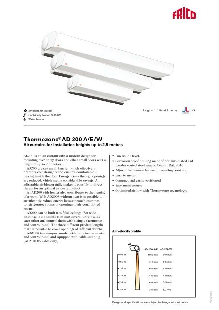
R Ambient, unheated Electrically heated 3-18 kW Water heated Lengths: 1, 1,5 and 2 metres Thermozone ® AD 200 A/E/W Air curtains for installation heights up to 2,5 metres AD200 is an air curtain with a modern design for mounting over entry doors and other small doors with a height of up to 2,5 metres. AD200 creates an air barrier, which effectively prevents cold draughts and ensures comfortable heating inside the door. Energy losses through openings are reduced, which means considerable savings. An adjustable air blower grille makes it possible to direct the air for an optimal air curtain effect. An AD200 with heater also contributes to the heating of a room. With AD200A without heat it is possible to significantly reduce energy losses through openings to refrigerated rooms or openings to air conditioned rooms. AD200 can be built into false ceilings. For wide openings it is possible to mount several units beside each other and control them with a single thermostat and control panel. The three different product lengths make it possible to cover openings of different widths. AD210C is a compact model with built-in thermostat and control panel and equipped with cable and plug (AD210C05 cable only). • Low sound level. • Corrosion proof housing made of hot zinc-plated and powder coated steel panels. Colour: RAL 9016. • Adjustable distance between mounting brackets. • Easy to mount. • Compact and easily positioned. • Easy maintenance. • Optimized airflow with Thermozone technology. Air velocity profile Design and specifications are subject to change without notice. 2008-05-06
- Page 2 and 3: Technical specifications | Thermozo
- Page 4 and 5: Mounting and installation Mounting
- Page 6 and 7: Complete control kits Ambient 1 Air
- Page 8: Water pressure drop charts Water pr
R<br />
Ambient, unheated<br />
Electrically heated 3-18 kW<br />
Water heated<br />
Lengths: 1, 1,5 and 2 metres<br />
Thermozone ® <strong>AD</strong> <strong>200</strong> A/E/W<br />
Air curtains for installation heights up to 2,5 metres<br />
<strong>AD</strong><strong>200</strong> is an air curtain with a modern design for<br />
mounting over entry doors and other small doors with a<br />
height of up to 2,5 metres.<br />
<strong>AD</strong><strong>200</strong> creates an air barrier, which effectively<br />
prevents cold draughts and ensures comfortable<br />
heating inside the door. Energy losses through openings<br />
are reduced, which means considerable savings. An<br />
adjustable air blower grille makes it possible to direct<br />
the air for an optimal air curtain effect.<br />
An <strong>AD</strong><strong>200</strong> with heater also contributes to the heating<br />
of a room. With <strong>AD</strong><strong>200</strong>A without heat it is possible to<br />
significantly reduce energy losses through openings<br />
to refrigerated rooms or openings to air conditioned<br />
rooms.<br />
<strong>AD</strong><strong>200</strong> can be built into false ceilings. For wide<br />
openings it is possible to mount several units beside<br />
each other and control them with a single thermostat<br />
and control panel. The three different product lengths<br />
make it possible to cover openings of different widths.<br />
<strong>AD</strong>210C is a compact model with built-in thermostat<br />
and control panel and equipped with cable and plug<br />
(<strong>AD</strong>210C05 cable only).<br />
• Low sound level.<br />
• Corrosion proof housing made of hot zinc-plated and<br />
powder coated steel panels. Colour: RAL 9016.<br />
• Adjustable distance between mounting brackets.<br />
• Easy to mount.<br />
• Compact and easily positioned.<br />
• Easy maintenance.<br />
• Optimized airflow with Thermozone technology.<br />
Air velocity profile<br />
Design and specifications are subject to change without notice.<br />
<strong>200</strong>8-05-06
Technical specifications | Thermozone <strong>AD</strong> <strong>200</strong> A, ambient unheated 1<br />
Type<br />
Output<br />
[kW]<br />
Airflow<br />
[m 3 /h]<br />
Sound level* 1<br />
[dB(A)]<br />
Voltage<br />
[V]<br />
Amperage<br />
[A]<br />
Length<br />
[mm]<br />
<strong>AD</strong>210A 0 900/1400 41/51 230V~ 0,5 1020 12<br />
<strong>AD</strong>215A 0 1300/2100 43/53 230V~ 0,6 1530 16<br />
<strong>AD</strong>220A 0 1800/2800 44/54 230V~ 1,0 1960 28<br />
Weight<br />
[kg]<br />
Technical specifications | Thermozone <strong>AD</strong> <strong>200</strong> E/C, electricallly heated 3<br />
Type<br />
Output steps<br />
[kW]<br />
Airflow<br />
[m 3 /h]<br />
Sound level* 1<br />
[dB(A)]<br />
∆t* 2<br />
[°C]<br />
Voltage<br />
[V]<br />
Amperage<br />
[A]<br />
Length<br />
[mm]<br />
<strong>AD</strong>210C03 0/2/3 900/1400 41/47 10/6 230V~ 13,5 1020 13<br />
<strong>AD</strong>210C05 0/2,3/4,5 900/1400 41/47 15/10 230V~ 20,1 1020 13<br />
<strong>AD</strong>210E03 0/1,5/3 900/1400 41/51 10/6 230V~/400V3N~* 3 13,5/4,8 1020 13<br />
<strong>AD</strong>210E06 0/3/6 900/1400 41/51 20/13 400V3N~* 3 9,2 1020 14<br />
<strong>AD</strong>210E09 0/4,5/9 900/1400 41/51 30/19 400V3N~* 3 13,5 1020 16<br />
<strong>AD</strong>215E05 0/2,3/4,5 1300/2100 43/53 10/6 400V3N~* 3 7,1 1530 19<br />
<strong>AD</strong>215E09 0/4,5/9 1300/2100 43/53 20/13 400V3N~* 3 13,6 1530 23<br />
<strong>AD</strong>215E14 0/6,7/13,5 1300/2100 43/53 34/21 400V3~ +230V~ 20,0 1530 23<br />
<strong>AD</strong>220E12 0/6/12 1800/2800 44/54 20/13 400V3~ +230V~ . * 4 18,2 1960 32<br />
<strong>AD</strong>220E18 0/9/18 1800/2800 44/54 30/19 400V3~ +230V~ , * 4 26,9 1960 32<br />
Weight<br />
[kg]<br />
Technical specifications | Thermozone <strong>AD</strong> <strong>200</strong> W, water heated 2<br />
Type Output* 5 Airflow Sound level* 1 ∆t* 2,5 Water<br />
volume<br />
Voltage Amperage Length Weight<br />
[kW] [m 3 /h] [dB(A)] [°C]<br />
[l]<br />
[V]<br />
[A]<br />
[mm] [kg]<br />
<strong>AD</strong>210W 7 750/1<strong>200</strong> 38/49 23/19 0,5 230V~ 0,5 1020 15<br />
<strong>AD</strong>215W 12 1100/1800 40/51 24/19 0,9 230V~ 0,6 1530 21<br />
<strong>AD</strong>220W 15 1500/2400 41/52 23/19 1,1 230V~ 1,0 1960 31<br />
* 1 ) Conditions: Distance to the unit 5 metres. Directional factor: 2. Equivalent absorption area: <strong>200</strong> m 2 .<br />
* 2 ) ∆t = temperature rise of passing air at maximum heat output and lowest/highest airflow.<br />
* 3 ) Or 400V3~ + 230V~ if the current is greater than 16 A.<br />
* 4 ) Heating elements are divided and powered by two separate supplies.<br />
* 5 ) Applicable at water temperature 80/60 °C, air temperature in +15 °C.<br />
Protection class <strong>AD</strong><strong>200</strong>A/W: (IP21)<br />
Protection class <strong>AD</strong><strong>200</strong>E: (IP21)<br />
Approved by SEMKO and CE compliant.
Dimensions<br />
Ambient / Electric<br />
185<br />
30<br />
30<br />
225<br />
10<br />
185<br />
225<br />
70 40<br />
122<br />
350<br />
Water<br />
Connection DN15 (1/2”)<br />
Inside thread<br />
70 40<br />
122<br />
350
Mounting and installation<br />
Mounting<br />
Thermozone <strong>AD</strong><strong>200</strong> can be permanently mounted on<br />
the wall or on the ceiling using threaded drop rods<br />
together with suspension kit, see next page. The air<br />
curtain can also be built into false ceilings, see Fig. 2.<br />
The unit can only be mounted horizontally, with the<br />
air outlet directed downwards. Minimum distance from<br />
outlet to flammable material is 50 mm.<br />
The distance between the mounting brackets is<br />
adjustable, which simplifies mounting. Brackets suitable<br />
for each unit are included on delivery. The 2 metre<br />
units should be fitted using three fixing points.<br />
For best effect the air curtain should cover the full<br />
width of the door and be placed as close to the opening<br />
as possible. For wider openings it is possible to place<br />
several units beside each other to create a continuous<br />
air curtain. The units should then be positioned as close<br />
together as possible.<br />
Min 60 mm<br />
370<br />
Connection <strong>AD</strong> <strong>200</strong>E 3<br />
The appliance should be isolated by a triple pole<br />
switch with at least 3 mm breaking gap. Connection is<br />
made through knock outs on the top side of the unit.<br />
For connection to the supply terminal block, a cable<br />
of maximum 16 mm 2 is used. For connection to the<br />
control terminal block, a cable of maximum 4 mm 2<br />
is used. For units with electrical heating, power and<br />
control should normally be supplied separately. For<br />
smaller units (current below 16 A), the supply could<br />
be common for both power and control, see technical<br />
specifications. For <strong>AD</strong>220E heating elements are divided<br />
and powered by two separate supplies. See wiring<br />
diagrams and dimension drawings.<br />
Connection <strong>AD</strong> <strong>200</strong>W 2<br />
The control cable is connected via a knock out on the<br />
top side to the right (seen from inside the building).<br />
Connections (DN15 (1/2”), inside thread) to the water<br />
heating coil are located on the top of the unit to the left<br />
(seen from inside the building). See wiring diagrams and<br />
dimension drawings.<br />
See over page for control kits and the chapter on<br />
Controls and accessories for further information.<br />
Type<br />
A (mm)<br />
<strong>AD</strong>210C03 min 50<br />
<strong>AD</strong>210C05 min 50<br />
<strong>AD</strong>210E03 min 50<br />
<strong>AD</strong>210E06 min 50<br />
<strong>AD</strong>210E09 min 100<br />
<strong>AD</strong>215E05 min 50<br />
<strong>AD</strong>215E09 min 50<br />
<strong>AD</strong>215E14 min 100<br />
<strong>AD</strong>220E12 min 50<br />
<strong>AD</strong>220E18 min 100<br />
Fig. 1: Minimum mounting distance<br />
False ceiling grille 2<strong>200</strong>3/2<strong>200</strong>4<br />
A<br />
Min 600 mm<br />
Space for service/inspection hatch<br />
Fig. 2: Mounting in a false ceilng
Mounting with suspension kit (extra)<br />
<strong>AD</strong>PK1<br />
2 x<br />
1 m<br />
<strong>AD</strong>PF1<br />
Threaded bars and M8 nuts are not<br />
included on delivery<br />
4 x<br />
161<br />
113<br />
40<br />
40<br />
7<br />
20<br />
9<br />
36<br />
30<br />
Ø9<br />
175
Complete control kits<br />
Ambient 1<br />
Airflow is controlled manually.<br />
Complete control kit:<br />
- CB30N, control box, controls the air flow in 3 steps<br />
Electric 3<br />
Level 1<br />
Airflow is controlled manually. Room thermostat<br />
controls the heat output in 2 steps.<br />
Control kit CK01E:<br />
- CB32N, control box, controls the airflow in 3 steps<br />
and heat output in 2 steps<br />
- RTI2, 2-step room thermostat<br />
Level 2<br />
Airflow and heat output are controlled automatically<br />
based on the opening of the door and the room<br />
temperature.<br />
When the door is open the fan runs on high speed,<br />
when the door closes the fan will continue to run for the<br />
desired time (2s–10 min.) set on MDC. When the door<br />
is closed the fan runs on low speed if there is a need for<br />
heating, if not the fan is switched off.<br />
The room thermostat controls the heat output.<br />
E.g. the thermostat is set on 23 °C and the difference<br />
between the steps 4 °C. The thermostat will activate<br />
below 19 °C when the door is closed. When the door<br />
opens, the thermostat will activate below 23 °C and<br />
normally the heat is switched on.<br />
Control kit CK02E:<br />
- CB32N, control box, controls the airflow in 3 steps<br />
and heat output in 2 steps<br />
- MDC, magnetic door contact with time delay<br />
- RTI2, 2-step room thermostat<br />
Level 3<br />
Airflow and heat output are controlled automatically<br />
based on the opening of the door, outdoor temperature<br />
and the room temperature.<br />
The system is based on an advanced microprocessing<br />
regulator in an attractive design.<br />
All parameters are pre-programmed for easy and<br />
quick installation.<br />
Control kit CK03:<br />
- <strong>AD</strong>EA, regulator (complete with outdoor sensor,<br />
built‐in room sensor and door contact)<br />
- <strong>AD</strong>EAIS, indoor sensor<br />
- <strong>AD</strong>EAEB, control board, for external mounting<br />
Read more about operation and usage of <strong>AD</strong>EA in<br />
chapter on Controls and accessories.<br />
Water 2<br />
Level 1<br />
Airflow is controlled manually. Room thermostat<br />
controls the heat output via actuator/valve.<br />
Control kit CK01W:<br />
- CB30N, control box , controls the airflow in 3 steps<br />
- T10, room thermostat IP30<br />
Note! A set of valves VR20 or VR25 or actuator+valve<br />
SD20+TVV20 or TVV25 should be added for a complete<br />
control kit.<br />
Level 2<br />
Airflow and heat output are controlled automatically<br />
based on the opening of the door and the room<br />
temperature.<br />
When the door is open the fan runs on high speed,<br />
when the door closes the fan will continue to run for the<br />
desired time (2s–10 min.) set on MDC. When the door<br />
is closed the fan runs on low speed if there is a need for<br />
heating, if not the fan is switched off.<br />
The room thermostat controls the heat output.<br />
E.g. the thermostat is set on 23 °C and the difference<br />
between the steps 4 °C. The thermostat will activate<br />
below 19 °C when the door is closed. When the door<br />
opens, the thermostat will activate below 23 °C and<br />
normally the heat is switched on.<br />
Control kit CK02W:<br />
- CB30N, control box, controls the airflow in 3 steps<br />
- MDC, magnetic door contact with time delay<br />
- RTI2, 2-step room thermostat<br />
Note! A set of valves VR20 or VR25 or actuator+valve<br />
SD20+TVV20 or TVV25 should be added for a complete<br />
control kit.<br />
Level 3<br />
Airflow and heat output are controlled automatically<br />
based on the opening of the door, outdoor temperature<br />
and the room temperature.<br />
The system is based on an advanced microprocessing<br />
regulator in an attractive design.<br />
All parameters are pre-programmed for easy and<br />
quick installation.<br />
Control kit CK03:<br />
- <strong>AD</strong>EA, regulator (complete with outdoor sensor,<br />
built‐in room sensor and door contact)<br />
- <strong>AD</strong>EAIS, indoor sensor<br />
- <strong>AD</strong>EAEB, control board, for external mounting-<br />
Note! A set of valves VR20 or VR25 or actuator+valve<br />
SD20+TVV20 or TVV25 should be added for a<br />
complete control kit.<br />
Read more about operation and usage of <strong>AD</strong>EA in<br />
chapter on Controls and accessories.<br />
See chapter on Controls and accessories or contact Frico for more options.
Output charts water<br />
Type<br />
Fan<br />
position<br />
Airflow<br />
[m 3 /h]<br />
Incoming / outgoing water temperature 90/70 °C<br />
Incoming air temp.= +15 °C Incoming air temp. = +20 °C<br />
Output Outgoing Water flow Output Outgoing<br />
air temp.<br />
air temp.<br />
[kW]<br />
[°C]<br />
[l/s]<br />
[kW]<br />
[°C]<br />
<strong>AD</strong>210W max 1<strong>200</strong> 9,3 37 0,11 8,5 41 0,10<br />
min 750 7,1 43 0,08 6,5 45 0,07<br />
<strong>AD</strong>215W max 1800 14,3 38 0,17 13,1 41 0,15<br />
min 1100 10,8 44 0,12 10,0 46 0,11<br />
<strong>AD</strong>220W max 2400 18,6 37 0,22 17,1 41 0,20<br />
min 1500 14,3 43 0,17 13,1 45 0,15<br />
Water flow<br />
[l/s]<br />
Type<br />
Fan<br />
position<br />
Airflow<br />
[m 3 /h]<br />
Incoming / outgoing water temperature 80/60 °C<br />
Incoming air temp.= +15 °C Incoming air temp. = +20 °C<br />
Output Outgoing Water flow Output Outgoing<br />
air temp.<br />
air temp.<br />
[kW]<br />
[°C]<br />
[l/s]<br />
[kW]<br />
[°C]<br />
<strong>AD</strong>210W max 1<strong>200</strong> 7,7 34 0,09 7,0 37 0,08<br />
min 750 6,0 38 0,07 5,4 41 0,06<br />
<strong>AD</strong>215W max 1800 11,9 34 0,14 10,7 37 0,12<br />
min 1100 9,0 39 0,10 8,2 42 0,09<br />
<strong>AD</strong>220W max 2400 15,5 34 0,18 14,0 37 0,16<br />
min 1500 11,9 38 0,14 10,8 41 0,12<br />
Water flow<br />
[l/s]<br />
Type<br />
Fan<br />
position<br />
Airflow<br />
[m 3 /h]<br />
Incoming / outgoing water temperature 60/50 °C<br />
Incoming air temp.= +15 °C Incoming air temp. = +20 °C<br />
Output Outgoing Water flow Output Outgoing<br />
air temp.<br />
air temp.<br />
[kW]<br />
[°C]<br />
[l/s]<br />
[kW]<br />
[°C]<br />
<strong>AD</strong>210W max 1<strong>200</strong> 5,7 29 0,13 5,0 32 0,11<br />
min 750 4,4 32 0,10 3,8 35 0,09<br />
<strong>AD</strong>215W max 1800 8,8 29 0,21 7,6 32 0,18<br />
min 1100 6,6 32 0,15 5,8 35 0,13<br />
<strong>AD</strong>220W max 2400 11,4 29 0,27 9,9 32 0,23<br />
min 1500 8,8 32 0,20 7,6 35 0,18<br />
Water flow<br />
[l/s]<br />
Type<br />
Fan<br />
position<br />
Airflow<br />
[m 3 /h]<br />
Incoming / outgoing water temperature 60/40 °C<br />
Incoming air temp.= +15 °C Incoming air temp. = +20 °C<br />
Output Outgoing Water flow Output Outgoing<br />
air temp.<br />
air temp.<br />
[kW]<br />
[°C]<br />
[l/s]<br />
[kW]<br />
[°C]<br />
<strong>AD</strong>210W max 1<strong>200</strong> 4,6 26 0,05 3,8 29 0,04<br />
min 750 3,6 29 0,04 3,0 32 0,03<br />
<strong>AD</strong>215W max 1800 7,1 26 0,08 5,9 29 0,07<br />
min 1100 5,4 29 0,06 4,5 32 0,05<br />
<strong>AD</strong>220W max 2400 9,3 26 0,11 7,7 29 0,09<br />
min 1500 7,2 29 0,08 6,0 32 0,07<br />
Water flow<br />
[l/s]
Water pressure drop charts<br />
Water pressure drop over watercoil <strong>AD</strong> <strong>200</strong>W<br />
Water flow [m 3 /h]<br />
0,1<br />
1,0<br />
10<br />
Pressure drop [kPa]<br />
70<br />
0,7<br />
Pressure drop [bar]<br />
10<br />
<strong>AD</strong>210W<br />
<strong>AD</strong>220W<br />
<strong>AD</strong>215W<br />
0,1<br />
1<br />
0,01 0,1 1,0<br />
Water flow [l/s]<br />
0,01<br />
Water pressure drop over controls and valves<br />
Water flow [m 3 /h]<br />
Pressure drop [kPa]<br />
70<br />
0,1<br />
1,0<br />
10<br />
0,7<br />
Pressure drop [bar]<br />
10<br />
0,1<br />
VR20<br />
TVV20<br />
VR25<br />
TVV25<br />
1<br />
0,01 0,1 1,0<br />
Water flow [l/s]<br />
0,01<br />
The pressure drop is calculated for an average temperature of 70 °C (PVV 80/60).<br />
For other water temperatures, the pressure drop is multiplied by the factor K.<br />
Average temp. water °C 40 50 60 70 80 90<br />
K 1.10 1.06 1.03 1.00 0.97 0.93


