Acoustical Panel - Wenger Corporation
Acoustical Panel - Wenger Corporation
Acoustical Panel - Wenger Corporation

You also want an ePaper? Increase the reach of your titles
YUMPU automatically turns print PDFs into web optimized ePapers that Google loves.
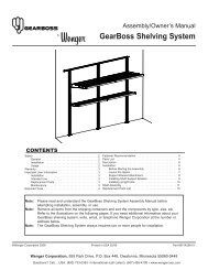
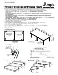
Owner’s Manual<br />
<strong>Acoustical</strong> <strong>Panel</strong><br />
Ceiling <strong>Panel</strong><br />
Wall <strong>Panel</strong><br />
Typical Wall <strong>Panel</strong><br />
CONTENTS<br />
Safety . . . . . . . . . . . . . . . . . . . . . . . . . . . . . . . . . . . . . . . . . . .2<br />
Fire Hazards . . . . . . . . . . . . . . . . . . . . . . . . . . . . . . . . . .3<br />
Warranty . . . . . . . . . . . . . . . . . . . . . . . . . . . . . . . . . . . . . . . . .4<br />
Important User Information . . . . . . . . . . . . . . . . . . . . . . . . . . .5<br />
Ceiling and Wall <strong>Panel</strong> Placement and Design . . . . . . .5<br />
Intended Use . . . . . . . . . . . . . . . . . . . . . . . . . . . . . . . . .5<br />
Handling <strong>Panel</strong>s . . . . . . . . . . . . . . . . . . . . . . . . . . . . . . . . . . .5<br />
Cleaning <strong>Panel</strong>s . . . . . . . . . . . . . . . . . . . . . . . . . . . . . . . . . . .6<br />
Cleaning Unfinished <strong>Panel</strong>s . . . . . . . . . . . . . . . . . . . . . .6<br />
Cleaning Painted <strong>Panel</strong>s . . . . . . . . . . . . . . . . . . . . . . . .6<br />
Cleaning Fabric-covered <strong>Panel</strong>s . . . . . . . . . . . . . . . . . .6<br />
Cleaning Absorber <strong>Panel</strong>s . . . . . . . . . . . . . . . . . . . . . . .6<br />
Painting Diffuser <strong>Panel</strong>s . . . . . . . . . . . . . . . . . . . . . . . . . . . . .6<br />
<strong>Panel</strong> System Description . . . . . . . . . . . . . . . . . . . . . . . . . . .7<br />
Ceiling <strong>Panel</strong> Definitions . . . . . . . . . . . . . . . . . . . . . . . .7<br />
<strong>Panel</strong> Types . . . . . . . . . . . . . . . . . . . . . . . . . . . . . . . . . .7<br />
Ceiling Grids . . . . . . . . . . . . . . . . . . . . . . . . . . . . . . . . . .7<br />
Ceiling <strong>Panel</strong> Types . . . . . . . . . . . . . . . . . . . . . . . . . . . .7<br />
Ceiling <strong>Panel</strong> Sizes . . . . . . . . . . . . . . . . . . . . . . . . . . . .9<br />
Wall <strong>Panel</strong> Definitions . . . . . . . . . . . . . . . . . . . . . . . . . . .10<br />
Wall <strong>Panel</strong> Sizes . . . . . . . . . . . . . . . . . . . . . . . . . . . . . . .11<br />
<strong>Panel</strong> Pre-installation . . . . . . . . . . . . . . . . . . . . . . . . . . . . . . .12<br />
Wall <strong>Panel</strong> Hardware Package Part List . . . . . . . . . . . .12<br />
Ceiling <strong>Panel</strong> Hardware Package Part List . . . . . . . . . .12<br />
Required Tools . . . . . . . . . . . . . . . . . . . . . . . . . . . . . . . .12<br />
Before Starting the Installation . . . . . . . . . . . . . . . . . . . .13<br />
<strong>Panel</strong> Installation Selector . . . . . . . . . . . . . . . . . . . . . . .13<br />
Rigid Ceiling Installation . . . . . . . . . . . . . . . . . . . . . . . . . . . . .14<br />
Fasten a Clip Model <strong>Panel</strong> Directly to Ceiling . . . . . . . .14<br />
Suspend the Clip Model <strong>Panel</strong> From Ceiling . . . . . . . . .15<br />
Standard Ceiling Grid installation . . . . . . . . . . . . . . . . . . . . . .17<br />
Lay-in Diffuser <strong>Panel</strong> Installation . . . . . . . . . . . . . . . . . .17<br />
Clip Model Diffuser or Absorber <strong>Panel</strong> Installation . . . . .18<br />
Designer Ceiling Grid Installation . . . . . . . . . . . . . . . . . . . . . .19<br />
Lay-in Diffuser <strong>Panel</strong> Installation . . . . . . . . . . . . . . . . . .19<br />
Clip Model Diffuser or Absorber <strong>Panel</strong> Installation . . . . .21<br />
Wall <strong>Panel</strong> Installation . . . . . . . . . . . . . . . . . . . . . . . . . . . . . .22<br />
Attach Hanger Brackets to Wall Diffuser <strong>Panel</strong>s . . . . . .22<br />
Wall <strong>Panel</strong> Locations . . . . . . . . . . . . . . . . . . . . . . . . . . .23<br />
Prepare the Wall Brackets . . . . . . . . . . . . . . . . . . . . . . .24<br />
Mark the Wall Bracket Locations . . . . . . . . . . . . . . . . . .26<br />
Attach the Wall Brackets . . . . . . . . . . . . . . . . . . . . . . . .28<br />
Attach the Wall <strong>Panel</strong> to the Wall . . . . . . . . . . . . . . . . . .30<br />
Note:<br />
Note:<br />
Note:<br />
Please read and understand the <strong>Acoustical</strong> <strong>Panel</strong> Owner’s Manual before starting any<br />
installation.<br />
Refer to the illustrations on the following pages. If you need additional information about<br />
your <strong>Acoustical</strong> <strong>Panel</strong>s, write, email, or telephone <strong>Wenger</strong> <strong>Corporation</strong> at the number or<br />
addresses below.<br />
Two people must work together for some assembly steps.<br />
©<strong>Wenger</strong> <strong>Corporation</strong> 2006 Printed in USA 10/06 Part #161G169-01<br />
<strong>Wenger</strong> <strong>Corporation</strong>, 555 Park Drive, P.O. Box 448, Owatonna, Minnesota 55060-0448<br />
Questions Call.....USA: (800) 733-0393 • International (call collect): (507) 455-4100 • www.wengercorp.com
SAFETY<br />
Throughout this manual you will find Cautions and Warnings which are defined as follows.<br />
• Warning means that failure to follow the instruction may result in serious injury or death.<br />
• Caution means that failure to follow the instruction may result in serious injury or damage to<br />
property.<br />
Note: Read all of these safety instructions before installing <strong>Wenger</strong> <strong>Acoustical</strong> Wall and Ceiling<br />
<strong>Panel</strong>s.<br />
Warning!<br />
Warning!<br />
Warning!<br />
Warning!<br />
Warning!<br />
Warning!<br />
Warning!<br />
Warning!<br />
Warning!<br />
Warning!<br />
Warning!<br />
Warning!<br />
Failure to comply with warnings and cautions in this document can result in damage<br />
to property or serious injury.<br />
Always make sure that all personnel including temporary workers that work on the<br />
<strong>Wenger</strong> <strong>Acoustical</strong> Wall and Ceiling <strong>Panel</strong>s have read and understand this manual.<br />
Failure to observe this warning can result in damage to property or serious injury.<br />
Always wear safety glasses, protective head gear, and safety shoes and use heavy<br />
work gloves when installing the <strong>Wenger</strong> <strong>Acoustical</strong> Wall and Ceiling <strong>Panel</strong>s. Failure to<br />
observe this warning can result in damage to property or serious injury.<br />
Always wear safety goggles when using low-pressure air for cleaning. Failure to<br />
observe this warning can result in serious injury. Failure to observe this warning can<br />
result in damage to property or serious injury.<br />
Some assembly steps require that two or more persons work together. Some<br />
components are heavy and are difficult to handle alone. Failure to observe this<br />
warning can result in damage to property or serious injury.<br />
Never modify or drill additional holes in panels. Possible damage to the panel<br />
structural integrity can result creating a dangerous situation that can lead to damage<br />
to property or serious injury.<br />
Never plug drain holes in Ceiling <strong>Panel</strong>s. Failure to observe this warning can cause<br />
Ceiling <strong>Panel</strong>s to fill with water if there is roof or plumbing leakage creating a<br />
dangerous situation. This can result in a catastrophic failure of the ceiling panel grid<br />
system resulting in damage to property, serious injury or death.<br />
When painting <strong>Panel</strong>s, always work outside or in a well ventilated space. Failure to<br />
observe this warning can result in serious injury.<br />
Never attach Wall <strong>Panel</strong>s to a ceiling or horizontal surface. Wall <strong>Panel</strong>s do not have<br />
provisions for drainage and can fill with water if there is roof or plumbing leakage. It<br />
is not permissible to drill drainage holes in Wall <strong>Panel</strong>s. Failure to observe this<br />
warning can result in damage to property or serious injury.<br />
Make sure that the hardware supplied by the end user is capable of supporting the<br />
<strong>Panel</strong>s and is safely anchored. Because ceiling construction such as Tectum® or<br />
acoustical tile may not be capable of supporting the <strong>Panel</strong> weight, make sure the<br />
fastener extends into a substrate or structural member capable of supporting the<br />
<strong>Panel</strong>. Failure to observe this warning can result in <strong>Panel</strong>s falling and causing<br />
damage to property or serious injury.<br />
Make sure that all four Ceiling Lay-in <strong>Panel</strong> Flanges rest on the ceiling grid rail flange.<br />
Improperly placed Ceiling <strong>Panel</strong>s can fall and cause serious injury or damage to<br />
property!<br />
Make sure that all four Clip Model <strong>Panel</strong> Mounting Clips rest on the ceiling grid rail.<br />
Improperly placed Ceiling <strong>Panel</strong>s can fall and cause serious injury or damage to<br />
property!<br />
2
SAFETY CONTINUED<br />
Warning!<br />
Warning!<br />
Warning!<br />
Warning!<br />
Caution!<br />
Never install Ceiling <strong>Panel</strong>s that are larger than four-feet by four-feet into a<br />
suspended ceiling grid system. Failure to observe this warning can result in <strong>Panel</strong>s<br />
falling and causing serious injury or damage to property.<br />
Do not install a Lay-in Diffuser <strong>Panel</strong> into a designer grid without attaching four<br />
Designer Grid Mounting Clips. Failure to observe this warning can result in <strong>Panel</strong>s<br />
falling and causing serious injury or damage to property.<br />
When attaching Mounting Clips to a Clip Model <strong>Panel</strong>, always install two Clips on one<br />
flange and two Clips on the opposite flange. Never attach one Clip on each flange.<br />
Failure to observe this warning can result in <strong>Panel</strong>s falling and causing serious injury<br />
or damage to property.<br />
Do not install a Clip-mounted Diffuser or Absorber <strong>Panel</strong>s into a suspended ceiling<br />
grid without attaching the Designer Grid Mounting Clips, two Clips on one side and<br />
two Clips on the opposite side. Failure to observe this warning can result in <strong>Panel</strong>s<br />
falling and causing serious injury or damage to property.<br />
Solvent based coatings containing aromatic hydrocarbon solvents such as lacquers<br />
or enamels are not recommended for use on PVC substrates. Failure to observe this<br />
caution can result in damage to the Diffuser <strong>Panel</strong>.<br />
FIRE HAZARDS<br />
Warning! The <strong>Acoustical</strong> <strong>Panel</strong>s are constructed from molded thermoplastic materials and can<br />
be covered with polyester fabric or paint. Do not allow open flames or very hot<br />
lighting to come into close proximity to any <strong>Acoustical</strong> <strong>Panel</strong>s. Lighting that is close<br />
to an <strong>Acoustical</strong> <strong>Panel</strong> must not exceed 176°F (80°C). Failure to observe this<br />
precaution can result in death, injury, or damage to property.<br />
3
WARRANTY<br />
The <strong>Acoustical</strong> Wall and Ceiling <strong>Panel</strong>s are guaranteed free of defects in materials and workmanship for<br />
five full years.<br />
Our guarantee assures you of either a full refund or repair or replacement of the defective<br />
materials or workmanship without charge, at the discretion of our Customer Service Department. Just<br />
call a Customer Service Representative at 1-800-887-7145 and state the reason you are dissatisfied. If<br />
a product return is necessary, your representative will issue a return authorization. This is your sole<br />
remedy for breach of this warranty.<br />
Should you have a question or problem with any <strong>Wenger</strong> product, don’t hesitate to call, even if the<br />
product is past warranty. It’s important to us that all our customers be satisfied.<br />
This is the sole warranty made by <strong>Wenger</strong>. <strong>Wenger</strong> disclaims all other warranties, including<br />
the warranties of merchantability and fitness for a particular purpose, as well as all liability for incidental,<br />
consequential, special, and indirect damage. <strong>Wenger</strong> liability for direct damages shall be limited to the<br />
amount you paid for the product involved. <strong>Wenger</strong> reserves the right to make product changes without<br />
obligation to incorporate such changes into products previously sold.<br />
Some states do not allow the exclusion or limitation of damages or warranties, so the above may not<br />
apply to you. This warranty gives you specific legal rights. You may also have other rights which vary<br />
from state to state.<br />
4
IMPORTANT USER INFORMATION<br />
CEILING AND WALL PANEL PLACEMENT AND DESIGN<br />
<strong>Wenger</strong> <strong>Acoustical</strong> Wall and Ceiling <strong>Panel</strong>s shape the acoustic properties of a room. Correct placement<br />
of Absorption and Diffusion <strong>Panel</strong>s in a room reduce unwanted reflections, fill dead-spots, and adjust<br />
reverberation levels to the optimum for the sound source.<br />
The acoustic design of a room must be tailored to the room’s shape, size, construction, and planned<br />
use. Simply adding Ceiling and Wall <strong>Panel</strong>s may not achieve the desired acoustic performance.<br />
Arranging Ceiling and Wall <strong>Panel</strong>s based on their visual appearance similarly may not achieve the best<br />
sound quality within the room. The best acoustic characteristics can be obtained by consulting <strong>Wenger</strong><br />
<strong>Corporation</strong> or an experienced acoustician and then developing an acoustic design for the room.<br />
INTENDED USE<br />
• <strong>Wenger</strong> <strong>Acoustical</strong> Wall and Ceiling <strong>Panel</strong>s are intended for indoor use in normal ambient<br />
temperature and humidity conditions and must not be exposed to open flames or hot lighting<br />
fixtures.<br />
• <strong>Wenger</strong> <strong>Acoustical</strong> Wall <strong>Panel</strong>s are intended to be permanently attached to permanent wall<br />
structures only as described in this manual.<br />
Warning! <strong>Acoustical</strong> Wall <strong>Panel</strong>s must never be attached to ceilings or other horizontal<br />
surfaces. Wall <strong>Panel</strong>s mounted horizontally do not have provisions for drainage and<br />
can fill with water if there is roof or plumbing leakage. It is not permissible to drill<br />
drainage holes in Wall <strong>Panel</strong>s. Failure to observe this warning can result in damage<br />
to property or serious injury.<br />
• <strong>Wenger</strong> <strong>Acoustical</strong> Ceiling <strong>Panel</strong>s are intended to be permanently attached to permanent ceiling<br />
structures as described in this manual.<br />
HANDLING PANELS<br />
Unfinished, painted, and fabric covered panel surfaces are easily soiled. Rough handling can easily<br />
damage panels and degrade the acoustic properties. When handling and installing <strong>Acoustical</strong> <strong>Panel</strong>s, do<br />
the following.<br />
• Always keep the entire installation site and installation tools as clean as possible.<br />
• Gloves are provided with the <strong>Panel</strong>s. Always wear these gloves whenever handling the panels.<br />
• Handle panels with care to prevent physical damage.<br />
• Two people must always work together when handling large panels.<br />
• Hold Absorber panels by the edge when handling or installing.<br />
• Never compress the Absorber <strong>Panel</strong> absorption material on the panel face (it will crush and not<br />
return to the original shape and degrade the acoustic properties).<br />
• Never modify or drill additional holes in panels. Damage to the panel’s structural integrity can result.<br />
Ceiling Diffuser <strong>Panel</strong>s have a small hole (or holes) in the lowest surface. These holes serve as a drain<br />
if there is roof or plumbing leakage. If the drain holes are plugged, the panel can fill with water<br />
increasing the total panel weight and ceiling panel grid system weight creating a dangerous situation.<br />
This can result in a catastrophic failure of the ceiling panel grid system and serious injury to<br />
people.<br />
.<br />
5
CLEANING PANELS<br />
CLEANING UNFINISHED PANELS<br />
Clean unpainted, white plastic Diffuser <strong>Panel</strong>s with a non-abrasive, mild detergent or household-window<br />
cleaner. Difficult to remove stains can be removed with a mildly-abrasive household cleaner if it is<br />
applied gently. Apply the mildly-abrasive household cleaner with gentle care to avoid hazing or<br />
scratching the panel finish.<br />
CLEANING PAINTED PANELS<br />
Clean painted plastic Diffuser <strong>Panel</strong>s only with mild soapy water. If it is necessary to use a commercial<br />
cleaner to remove a difficult stain, try the cleaner on a hidden area first to see if the paint is affected by<br />
the cleaner (to make sure that the cleaner does not bleach or remove the paint entirely).<br />
CLEANING FABRIC-COVERED PANELS<br />
Clean fabric-covered panels by vacuuming with a soft brush attachment or using a low-pressure air<br />
nozzle outdoors or in a well ventilated space.<br />
Warning! Always wear safety goggles when using low-pressure air for cleaning. Failure to<br />
observe this warning can result in serious injury.<br />
The <strong>Wenger</strong> standard fabric is polyester. Stains can be removed by using a fabric cleaner designed for<br />
polyester. Blotting a soiled area is recommended. Brushing or other aggressive methods can damage<br />
the fabric and should be avoided. It is always a good practice to test the cleaning method and solution<br />
on the back side of the <strong>Panel</strong> to make sure that the fabric color, texture, and adhesion are not affected.<br />
Caution! Always follow all of the fabric cleaner manufacturer’s application and safety<br />
instructions.<br />
To clean custom fabrics, use only cleaners and methods that are recommended by the fabric<br />
manufacturer.<br />
CLEANING ABSORBER PANELS<br />
Never use excessive amounts of water or liquid cleaners on absorber panels. Absorber panels absorb<br />
liquids and required extended time to dry promoting mold and mildew growth<br />
PAINTING DIFFUSER PANELS<br />
Unpainted Diffuser <strong>Panel</strong>s can be painted without significantly reducing the acoustical performance.<br />
Always test the paint or stain on a small hidden area of the panel first.<br />
Caution! Solvent based coatings containing aromatic hydrocarbon solvents such as lacquers<br />
or enamels are not recommended for use on PVC substrates. Failure to observe this<br />
caution can result in damage to the Diffuser <strong>Panel</strong>.<br />
To paint a Diffuser <strong>Panel</strong>, do as follows.<br />
1. Select a flat, satin, semi-gloss, or high-gloss latex or acrylic-latex paint suitable for exterior surfaces.<br />
2. Clean and dry the Diffuser <strong>Panel</strong> surface to be painted.<br />
3. Apply the paint at ambient temperatures between 50°F and 90°F, at least 5°F above the dew point,<br />
and with the relative humidity less than 85-percent.<br />
a. Apply the first coat of paint with a brush and allow the paint to dry.<br />
b. Apply the second coat of paint with a roller or paint sprayer.<br />
4. To apply a stain to Diffuser <strong>Panel</strong>, clean the surface and then follow the manufacturer’s<br />
recommended application instructions.<br />
5. Unplug all drain holes after painting panels.<br />
6
PANEL SYSTEM DESCRIPTION<br />
PANEL TYPES<br />
<strong>Wenger</strong> <strong>Corporation</strong> manufactures different types of Wall and Ceiling <strong>Panel</strong>s.<br />
• Type I Convex Diffuser <strong>Panel</strong> — constructed with a composition material that is poly-cylindrical in<br />
shape, the <strong>Panel</strong> scatters and blends mid-range to high-range audio frequencies.<br />
• Type II Convex Diffuser <strong>Panel</strong> — similar to but larger than the Type I Diffuser <strong>Panel</strong>. The Type II<br />
<strong>Panel</strong> performs like the Type I <strong>Panel</strong> but also absorbs some low-range audio frequencies.<br />
• Quadratic Diffuser <strong>Panel</strong> — constructed of recycled molded thermoplastic, the <strong>Panel</strong> scatters and<br />
blends audio frequencies from 750 Hertz to 3300 Hertz. These <strong>Panel</strong>s are available only as a fourfoot<br />
by four-foot size to fit into Lay-in Ceiling Grid Systems.<br />
• Pyramid Diffuser <strong>Panel</strong> — constructed of recycled molded thermoplastic, the <strong>Panel</strong> is shaped like<br />
an offset pyramid and is used to shape specific acoustical applications.<br />
• Absorber <strong>Panel</strong>s — constructed of sound-absorptive, fabric-covered, glass-fiber material that is flat<br />
in shape, the <strong>Panel</strong> absorbs a broad range of audio frequencies.<br />
CEILING PANEL DEFINITIONS<br />
Absorber Ceiling <strong>Panel</strong> — flat, fabric covered panel that<br />
absorbs sound and reduces reverberation. This <strong>Panel</strong> uses<br />
Mounting Clips for installation.<br />
Convex Clip Model Ceiling <strong>Panel</strong> — poly-cylindrical diffuser<br />
panel that scatters sound. The <strong>Panel</strong> uses Mounting Clips,<br />
Designer Grid Clips, or Hanger Brackets to attach directly to the<br />
ceiling, rest in a ceiling grid, or suspend from ceiling hardware.<br />
Convex Lay-in Model Ceiling <strong>Panel</strong> — poly-cylindrical diffuser panel that<br />
scatters sound. The <strong>Panel</strong> has a flange on the perimeter that allows resting the<br />
flange directly onto a ceiling grid rail flange. Also, Designer Grid Clips can be<br />
attached and used to rest in a designer ceiling grid.<br />
Low Profile Pyramid Lay-in Model Ceiling<br />
<strong>Panel</strong> — pyramid shaped diffuser panel that<br />
scatters sound. The <strong>Panel</strong> has a flange on the<br />
perimeter that allows resting the flange directly<br />
onto a ceiling grid. Also, Designer Grid Clips can<br />
be used to rest in a designer ceiling grid.<br />
Low Profile Trapezoid Lay-in Model Ceiling <strong>Panel</strong> — trapezoidal shaped<br />
diffuser panel that scatters sound. The <strong>Panel</strong> has a flange on the perimeter that<br />
allows resting the flange directly onto a ceiling grid. Also, Designer Grid Clips can<br />
be used to rest in a designer ceiling grid.<br />
7
PANEL SYSTEM DESCRIPTION CONTINUED<br />
CEILING PANEL DEFINITIONS CONTINUED<br />
Grid Center-to-Center Distance<br />
Grid Rails<br />
Ceiling Grid — grid rails, connected<br />
at right angles to each other,<br />
suspended from the ceiling with<br />
hardware. The grid rails allow Ceiling<br />
<strong>Panel</strong>s to rest on the rails.<br />
Grid Center-to-Center Distance<br />
Standard Ceiling Grid Rail — grid rail flange is 15/16-inch or<br />
greater and is adequate for supporting a Lay-in <strong>Panel</strong> Flange.<br />
Designer Ceiling Grid Rail — grid rail flange is<br />
less than15/16-inch and is not adequate for<br />
supporting a Lay-in <strong>Panel</strong> Flange.<br />
Rail Flange is greater than<br />
15/16-inch (2.38 cm)<br />
Designer Grid Mounting Clip — a hook shaped bracket<br />
with clearance holes that allows attaching the bracket to<br />
either a Lay-in Model <strong>Panel</strong> or a Clip Model <strong>Panel</strong>. The<br />
hook fits over a Grid Rail.<br />
Rail Flange is less than<br />
15/16-inch (2.38 cm)<br />
Hanger Bracket — a U-shaped bracket with clearance holes<br />
that allows attaching the bracket to the Corner Braces on either<br />
a Lay-in Model <strong>Panel</strong> or a Clip Model <strong>Panel</strong>. The Bracket is<br />
used to suspend <strong>Panel</strong>s from the ceiling with hardware supplied<br />
by the end user.<br />
Pan Head Screw — Phillips sheet metal pan head screw,<br />
6-20x1/2-inch, used to attach brackets to the Ceiling <strong>Panel</strong><br />
Corner Braces.<br />
Mounting Clip — a flat bracket with clearance holes that allow attaching the<br />
bracket to the Corner Braces on either a Lay-in Model <strong>Panel</strong> or a Clip Model<br />
<strong>Panel</strong>. The Bracket is used to attach a <strong>Panel</strong> directly to a Rigid Ceiling or to rest<br />
the <strong>Panel</strong> in Ceiling Grid System.<br />
Rigid Ceiling (not shown) — a non-grid suspended ceiling that is integral to the<br />
building structure (such as truss and deck construction) or is rigidly attached to<br />
the building structure without removable panels.<br />
Suspended Ceiling (not shown) — a system of rails (Ceiling Grid) and<br />
removable ceiling panels commonly used for the ease of installation and low cost.<br />
8
PANEL SYSTEM DESCRIPTION CONTINUED<br />
CEILING PANEL SIZES<br />
Most domestic suspended ceiling grid systems have grid rails on two-foot square centers (61 cm), twofoot<br />
by four-foot centers (61 x 122 cm), or four-foot (122 cm) square centers. This allows the installation<br />
of English sized two-foot by two-foot, two-foot by four-foot, and four-foot by four-foot Ceiling <strong>Panel</strong>s to<br />
match the center-to-center grid distance.<br />
Many of <strong>Wenger</strong> Ceiling <strong>Panel</strong>s are made specifically for suspended grid ceiling systems and are<br />
referred to by their English grid size such as 2x2 (two-foot by two-foot). The actual size of these <strong>Panel</strong>s<br />
is different than the nominal size. A 2x2 Ceiling <strong>Panel</strong> is actually slightly smaller than two-feet by twofeet<br />
to allow for the grid rail to fit between the Ceiling <strong>Panel</strong>s.<br />
Ceiling <strong>Panel</strong>s larger than 4x4 have the same size characteristics but, because the weight of the <strong>Panel</strong>s,<br />
are not intended to be installed in a suspended ceiling grid system.<br />
Absorber <strong>Panel</strong>s are available in custom sizes that are built to exact outside dimensions that are<br />
specified on the panel purchase order.<br />
2x2 Convex Clip Model<br />
22.750" x 22.750"<br />
(57.8 x 57.8 cm)<br />
4x2 Convex Clip Model<br />
23.125" x 46.875"<br />
(58.7 x 119 cm)<br />
4x4 Convex Clip Model<br />
46.750" x 46.750"<br />
(118.7 x 118.7 cm)<br />
4x4 Pyramid Clip Model<br />
46.750" x 46.750"<br />
(118.7 x 118.7 cm)<br />
4x4 Pyramid Lay-in Model<br />
46.750" x 46.750"<br />
(118.7 x 118.7 cm)<br />
4x4 Convex Lay-in Model<br />
46.750" x 46.750"<br />
(118.7 x 118.7 cm)<br />
4x2 Convex Lay-in Model<br />
23.125" x 46.875"<br />
(58.7 x 119 cm)<br />
4x2 Convex Lay-in Model<br />
22.750" x 22.750"<br />
(57.8 x 57.8 cm)<br />
4x4 Low Profile Pyramid Lay-in Model<br />
47.625" x 47.625"<br />
(121 x 121 cm)<br />
4x4 Low Profile Trapezoid Lay-in<br />
Model 47.625" x 47.625"<br />
(121 x 121 cm)<br />
2x2 Low Profile Trapezoid Lay-in<br />
Model 23.625" x 23.625"<br />
(60 x 60 cm)<br />
Absorber <strong>Panel</strong><br />
Nominal 2-foot size is 23.15" (56.3 cm)<br />
Nominal 3-foot size is 35.15" (89.3 cm)<br />
Nominal 4-foot size is 46.90" (119.1 cm)<br />
Absorber <strong>Panel</strong>s can be ordered and built to<br />
exact outside dimensions.<br />
2x2 Low Profile Pyramid Lay-in Model<br />
23.625" x 23.625"<br />
(60 x 60 cm)<br />
9
PANEL SYSTEM DESCRIPTION CONTINUED<br />
WALL PANEL DEFINITIONS<br />
Absorber Wall <strong>Panel</strong> — flat, fabric covered panel that absorbs sound and reduces<br />
reverberation. This <strong>Panel</strong> uses Wall Mounting Brackets for installation.<br />
Convex Model Wall <strong>Panel</strong> — poly-cylindrical shaped diffuser<br />
panel that scatters sound. This <strong>Panel</strong> uses Wall Mounting<br />
Brackets for installation.<br />
Pyramid Model Wall <strong>Panel</strong> — pyramid shaped diffuser panel<br />
that scatters sound. This <strong>Panel</strong> uses Wall Mounting Brackets<br />
for installation.<br />
Hanger Bracket — Z-shaped bracket that attaches to<br />
the Diffuser Wall <strong>Panel</strong> Corner Braces and engages<br />
the Wall Bracket at installation.<br />
Wall Bracket — offset metal rail that attaches to the wall and receives the<br />
Wall <strong>Panel</strong> Hanger Brackets when installing the Wall <strong>Panel</strong>.<br />
Pan Head Screw — Phillips sheet metal pan head screw,<br />
6-20x1/2-inch, used to attach brackets to the Wall <strong>Panel</strong><br />
Corner Braces.<br />
10
PANEL SYSTEM DESCRIPTION CONTINUED<br />
WALL PANEL SIZES<br />
<strong>Wenger</strong> Convex Diffuser Wall <strong>Panel</strong>s are made to attach directly to a permanent wall structure and are<br />
referred to by their English size such as 2x2 (two-foot by two-foot). The actual size of these <strong>Panel</strong>s is<br />
different than the nominal size. A 2x2 Ceiling <strong>Panel</strong> is actually slightly smaller than two-feet by two-feet.<br />
Absorber <strong>Panel</strong>s are available in custom sizes that are built to exact outside dimensions that are<br />
specified on the panel purchase order.<br />
4x4 Pyramid <strong>Panel</strong><br />
46.750" x 46.750"<br />
(118.7 x 118.7 cm)<br />
3x3 Convex <strong>Panel</strong><br />
35.250" x 35.250"<br />
(89.5 x 89.5 cm)<br />
3x4 Convex <strong>Panel</strong><br />
35.250" x 47.000"<br />
(89.5 x 119.4 cm)<br />
3x6 Convex Pane<br />
35.250" x 70.813"<br />
(89.5 x 180 cm)<br />
2x2 Convex <strong>Panel</strong><br />
22.750" x 22.750"<br />
(57.8 x 57.8 cm)<br />
4x2 Convex <strong>Panel</strong><br />
23.125" x 46.875"’<br />
(58.8 x 119 cm)<br />
4x3 Convex <strong>Panel</strong><br />
35.250" x 47.000"<br />
(89.5 x 119.4 cm)<br />
4x4 Convex <strong>Panel</strong><br />
46.750" x 46.750"<br />
(118.7 x 118.7 cm)<br />
Absorber <strong>Panel</strong><br />
Nominal 2-foot dimension is 23.15" (56.3 cm)<br />
Nominal 3-foot dimension is 35.15" (89.3 cm)<br />
Nominal 4-foot dimension is 46.90" (119.1 cm)<br />
Nominal 5-foot dimension is 58.90" (149.6 cm)<br />
Nominal 6-foot dimension is 70.90" (180 cm)<br />
Nominal 8-foot dimension is 94.90" (240.7 cm)<br />
4x6 Convex <strong>Panel</strong><br />
47.000" x 70.875"<br />
(119.4 x 180 cm)<br />
Absorber <strong>Panel</strong>s can be ordered and built to exact outside dimensions.<br />
4x8 Convex <strong>Panel</strong><br />
46.875 " x 94.750"<br />
(58.8 x 240.7 cm)<br />
11
PANEL PRE-INSTALLATION<br />
REQUIRED TOOLS<br />
Some of the following tools are required for installation of Wall and Ceiling <strong>Panel</strong>s. Refer to the<br />
installation instructions for specific information.<br />
Carpenter’s Box Level<br />
Chalk Line<br />
#30 Drill Bit Number 2B Pencil<br />
Cordless Drill<br />
#2 Phillips Bit #2 Phillips Screwdriver<br />
8-foot Tape Rule Blind Rivet Tool Plumb Bob<br />
CEILING PANEL HARDWARE PACKAGE PART LIST<br />
Each Ceiling <strong>Panel</strong> is furnished with a hardware Package that<br />
contains the following parts. Parts not required for installation<br />
should be discarded.<br />
Item Quantity Description<br />
1 8 Pan Head Screw, 6-20x1/2-inch<br />
2 4 Designer Grid Bracket<br />
3 4 Hanger Bracket<br />
4 4 Mounting Clip<br />
WALL PANEL HARDWARE PACKAGE PART LIST<br />
Each Wall <strong>Panel</strong> is furnished with a hardware Package that<br />
contains the following parts. Parts not required for installation<br />
should be discarded.<br />
Item Quantity Description<br />
1 8 Pan Head Screw, 6-20x1/2-inch<br />
2 4 Diffuser Wall Hanger Bracket<br />
3 2 Wall Bracket<br />
12
PANEL PRE-INSTALLATION CONTINUED<br />
PANEL INSTALLATION SELECTOR<br />
• To install a Wall <strong>Panel</strong>, go to page 22.<br />
• To install a Ceiling <strong>Panel</strong>, use the flow chart below to find the installation instruction. Refer to pages<br />
7 and 8 for the definitions of a Standard Grid Ceiling and a Designer Grid Ceiling.<br />
BEFORE STARTING THE INSTALLATION<br />
1. Make sure that all personnel (including temporary labor) installing <strong>Acoustical</strong> <strong>Panel</strong>s read and<br />
understand the warnings, cautions, and installation instructions in this manual.<br />
2. Consult local building codes and fire codes before starting the installation.<br />
3. Use the installation drawing supplied by <strong>Wenger</strong> <strong>Corporation</strong> or the architect showing the location<br />
and orientation of each <strong>Panel</strong>.<br />
4. Remove all items from the shipping containers and make sure that all parts including the fasteners<br />
and accessories in the Hardware Packages are present. Refer to the Hardware Package Part List<br />
on page 12.<br />
5. Use the <strong>Panel</strong> Installation Selector above to select the correct installation instructions.<br />
6. If problems are encountered during the installation, call <strong>Wenger</strong> Customer Service at (800) 733-<br />
0393<br />
13
RIGID CEILING INSTALLATION<br />
FASTEN A CLIP MODEL PANEL DIRECTLY TO CEILING<br />
Warning! Do not perform the installation before reading and understanding all of the warnings<br />
and cautions on page 2 and 3 and observing these during the installation. Failure to<br />
observe this warning can result in serious injury or damage to property.<br />
Clip Model Diffuser and Absorber <strong>Panel</strong>s attach directly to the Ceiling as follows.<br />
1. Attach one Mounting Clip to each Corner Brace with two Sheet Metal Screws, 6-20x1/2-inch, as<br />
shown in illustration 1 below. The Ceiling Mounting Hole must be outside of the <strong>Panel</strong> perimeter.<br />
Note: Install Mounting Clips only on two sides of the <strong>Panel</strong> as shown in illustration 1.<br />
2. Hold the <strong>Panel</strong> against the ceiling in the exact installation position and mark the center of the<br />
each Ceiling Mounting Hole as shown in illustration 2 below.<br />
Ceiling Mounting Hole<br />
1<br />
Pan Head Sheet Metal Screw, 6-20x1/2-inch<br />
Mounting Clip Ceiling Mounting Hole<br />
Mounting Clip<br />
Mark the four Ceiling Mounting<br />
Hole locations on the ceiling.<br />
Corner Brace<br />
2<br />
Clip Mounting Holes<br />
Corner Brace<br />
Clip Model <strong>Panel</strong><br />
Clip Model <strong>Panel</strong><br />
3. Attach the <strong>Panel</strong> to the ceiling using an<br />
appropriate fastener (not supplied).<br />
Note: Ceiling construction and materials vary.<br />
Always consult local codes or building<br />
material suppliers for information regarding<br />
the correct fastener.<br />
Warning! Many ceilings do not have sufficient<br />
structure to support the <strong>Panel</strong><br />
weight. To install a <strong>Panel</strong> to a<br />
material such as Tectum® or an<br />
acoustical tile, make sure that the<br />
fasteners extend into a substrate or<br />
structural member capable of<br />
supporting the <strong>Panel</strong>. Failure to<br />
observe this warning can result in<br />
<strong>Panel</strong>s falling and result in damage<br />
to property or serious injury.<br />
Mounting Clip<br />
Mounting Clip<br />
Attach to ceiling with a fastener<br />
in each Mounting Hole.<br />
Ceiling Mounting Holes<br />
3<br />
Clip Model Ceiling <strong>Panel</strong><br />
Ceiling Mounting Fastener<br />
(not supplied)<br />
14
RIGID CEILING INSTALLATION CONTINUED<br />
SUSPEND THE CLIP MODEL PANEL FROM CEILING<br />
Warning! Do not perform the installation before reading and understanding all of the warnings<br />
and cautions on page 2 and 3 and observing these during the installation. Failure to<br />
observe this warning can result in serious injury or damage to property.<br />
1. Hold the <strong>Panel</strong> against the ceiling in it’s exact mounting position and draw an outline around the<br />
<strong>Panel</strong> perimeter as shown in illustration 1 below. Use a plumb bob to mark the corners if the <strong>Panel</strong><br />
cannot be held against the ceiling.<br />
2. Mark four points, 4-1/2-inches (11.43 cm) inside each side of the <strong>Panel</strong> perimeter as shown in the<br />
illustration 2 below.<br />
<strong>Panel</strong> Perimeter<br />
Mark the Clip-mounted <strong>Panel</strong> perimeter<br />
onto the Ceiling.<br />
1<br />
2<br />
Mark four points inside<br />
the <strong>Panel</strong> perimeter<br />
<strong>Panel</strong> Perimeter<br />
4-1/2" (11.43 cm)<br />
4-1/2"<br />
(11.43 cm)<br />
3. Attach one Hanger Bracket to each Corner Brace with two Pan Head Screws, 6-20x1/2-inch, as<br />
shown in the illustration 3 below.<br />
Pan Head Screw, 6-20x1/2"<br />
Hanger Bracket<br />
Hanger Bracket<br />
<strong>Panel</strong> Corner<br />
Brace<br />
3<br />
<strong>Panel</strong> Corner Brace<br />
15
RIGID CEILING INSTALLATION CONTINUED<br />
SUSPEND THE CLIP MODEL PANEL FROM CEILING CONTINUED<br />
4. Attach fasteners (not supplied by <strong>Wenger</strong> <strong>Corporation</strong>) to the ceiling at the four points marked inside<br />
the <strong>Panel</strong> Perimeter in step 2 on the previous page.<br />
Warning! Make sure that the hardware supplied by the end user is capable of supporting the<br />
<strong>Panel</strong>s and is safely anchored. Because ceiling construction such as Tectum® or<br />
acoustical tile may not be capable of supporting the <strong>Panel</strong> weight, make sure the<br />
fastener extends into a substrate or structural member capable of supporting the<br />
<strong>Panel</strong>. Failure to observe this warning can result in <strong>Panel</strong>s falling and causing<br />
damage to property or serious injury.<br />
5. Using wire, cable, or some suitable material (not supplied by <strong>Wenger</strong> <strong>Corporation</strong>), attach the four<br />
Hanger Brackets to the four fasteners as shown in the illustration 5 below (or by some other safe<br />
method).<br />
Eyebolt or other suitable<br />
fastener supplied by the<br />
end user<br />
Wire or other suitable<br />
material supplied by the<br />
end user<br />
5<br />
Wire or other suitable material<br />
supplied by the end user<br />
Hanger Bracket<br />
16
STANDARD CEILING GRID INSTALLATION<br />
LAY-IN DIFFUSER PANEL INSTALLATION<br />
Warning! Do not perform the installation before reading and understanding all of the warnings<br />
and cautions on page 2 and 3 and observing these during the installation. Failure to<br />
observe this warning can result in serious injury or damage to property.<br />
Lay-in Model Ceiling <strong>Panel</strong>s are installed into the standard ceiling grid without additional hardware.<br />
1. Insert a Lay-in Model Ceiling <strong>Panel</strong> upward through the ceiling grid as shown in illustration 1.<br />
1<br />
Lay-in Model Ceiling <strong>Panel</strong><br />
Ceiling Grid<br />
2. Orient the Ceiling <strong>Panel</strong> above the ceiling grid and lower the <strong>Panel</strong> into the grid making sure that all<br />
four flanges on the <strong>Panel</strong> rest on the grid rails as shown in illustration 2 below.<br />
Warning! Make sure that all four Ceiling <strong>Panel</strong> Flanges rest on the grid. Improperly placed<br />
Ceiling <strong>Panel</strong>s can fall and cause serious injury or damage to property!<br />
Lay-in Model Ceiling<br />
<strong>Panel</strong> Flange<br />
2<br />
Lay-in Model Ceiling<br />
<strong>Panel</strong> Flange<br />
Standard Ceiling Grid<br />
Standard Ceiling Grid<br />
17
STANDARD CEILING GRID INSTALLATION CONTINUED<br />
CLIP MODEL DIFFUSER OR ABSORBER PANEL INSTALLATION<br />
Warning! Do not perform the installation before reading and understanding all of the warnings<br />
and cautions on page 2 and 3 and observing these during the installation. Failure to<br />
observe this warning can result in serious injury or damage to property.<br />
Clip Model Diffuser or Absorber <strong>Panel</strong>s are installed into a standard ceiling grid after attaching four<br />
Mounting Clips to the <strong>Panel</strong>.<br />
1. Attach one Mounting Clip to each Corner Brace with two Sheet Metal Screws, 6-20x1/2-inch as<br />
shown below. The Ceiling Mounting Hole must be placed inside of the <strong>Panel</strong> perimeter.<br />
Note: Install Mounting Clips only on two opposite sides of the <strong>Panel</strong> as shown in illustration 1 below.<br />
Pan Head Sheet Metal Screw, 6-20x1/2-inch<br />
Mounting Clip Holes<br />
Ceiling Mounting Hole<br />
Ceiling Mounting Hole<br />
Mounting Clip<br />
Mounting Clip<br />
Corner Brace<br />
Clip Model Ceiling <strong>Panel</strong><br />
Corner Brace<br />
1<br />
2. Insert a Clip Model Ceiling <strong>Panel</strong> upward<br />
through the ceiling grid.<br />
2<br />
Ceiling Grid<br />
Clip Model Ceiling <strong>Panel</strong><br />
3. Orient the Ceiling <strong>Panel</strong> above the ceiling grid and lower the <strong>Panel</strong> into the grid making sure that all<br />
four Mounting Clips on the <strong>Panel</strong> rest on the ceiling grid rails as shown in illustration 3.<br />
Warning! Make sure that all four Mounting Clips rest on the grid. Improperly placed Ceiling<br />
<strong>Panel</strong>s can fall and cause serious injury or damage to property!<br />
Mounting Clip<br />
3<br />
Mounting Clip<br />
Clip Model Ceiling <strong>Panel</strong><br />
Standard Ceiling Grid<br />
18
DESIGNER CEILING GRID INSTALLATION<br />
LAY-IN DIFFUSER PANEL INSTALLATION<br />
Warning! Do not perform the installation before reading and understanding all of the warnings<br />
and cautions on page 2 and 3 and observing these during the installation. Failure to<br />
observe this warning can result in serious injury or damage to property.<br />
Warning! Do not install a Lay-in Diffuser <strong>Panel</strong> into a designer grid without attaching the<br />
Designer Grid Mounting Clip. Failure to observe this warning can result in <strong>Panel</strong>s<br />
falling and causing serious injury or damage to property.<br />
1. Attach the Designer Grid Mounting Clips to the Lay-in <strong>Panel</strong> as follows.<br />
Warning! Do not install a single Clip on each <strong>Panel</strong> flange. Install two Clips on one flange and<br />
two Clips on the opposite flange. Failure to observe this warning can result in <strong>Panel</strong>s<br />
falling and causing serious injury or damage to property.<br />
a. Using a Designer Grid Mounting Clip as a template, mark four hole locations on one flange of a<br />
Diffuser <strong>Panel</strong> as shown in illustration 1a below. Each two-hole pattern should be about eightinches<br />
from the end of the panel.<br />
b. Using a number-30 drill bit (0.1285-inch), drill four holes in the Lay-in Diffuser <strong>Panel</strong> flange as<br />
shown in illustration 1b below.<br />
c. Using a blind rivet tool, attach each Designer Grid Mounting Clip to the Lay-in <strong>Panel</strong> Flange by<br />
inserting two 1/8-inch Blind Rivets upward through the two Drilled Holes and the two Mounting<br />
Clip Rivet Clearance Holes.<br />
d. Repeat steps a to c on the opposite Lay-in <strong>Panel</strong> flange.<br />
Designer Grid<br />
Mounting Clip<br />
8-inches<br />
(20 cm)<br />
Rivet Clearance Holes<br />
Designer Grid<br />
Mounting Clip<br />
Lay-in Diffuser <strong>Panel</strong><br />
1/4-inch (0.64 cm)<br />
1<br />
Drilled Hole (#30 or<br />
.1285-inch diameter)<br />
1-1/2-inch<br />
(3.81 cm)<br />
1/8-inch Blind Rivet<br />
19
DESIGNER CEILING GRID INSTALLATION CONTINUED<br />
LAY-IN DIFFUSER PANEL INSTALLATION CONTINUED<br />
2. Insert a Lay-in Diffuser Model Ceiling <strong>Panel</strong> with Designer Grid Mounting Clips upward through the<br />
ceiling grid.<br />
2<br />
Ceiling Grid<br />
Clip Model Ceiling <strong>Panel</strong><br />
Designer Grid<br />
Mounting Clip<br />
3. Orient the Diffuser Ceiling <strong>Panel</strong> above the ceiling grid and lower the <strong>Panel</strong> into the grid making<br />
sure that all four Designer Grid Mounting Clips on the <strong>Panel</strong> rest on the grid rails as shown below.<br />
Warning! Make sure that all four Mounting Clips rest on the grid. Improperly placed Ceiling<br />
<strong>Panel</strong>s can fall and cause serious injury or damage to property!<br />
Lay-in Diffuser <strong>Panel</strong><br />
Designer Grid<br />
Mounting Clip<br />
Designer Grid Mounting Clip<br />
Designer Ceiling Grid<br />
Designer Ceiling Grid<br />
3<br />
20
DESIGNER CEILING GRID INSTALLATION CONTINUED<br />
CLIP MODEL DIFFUSER OR ABSORBER PANEL INSTALLATION<br />
Warning! Do not perform the installation before reading and understanding all of the warnings<br />
and cautions on page 2 and 3 and observing these during the installation. Failure to<br />
observe this warning can result in serious injury or damage to property.<br />
Warning! Do not install a Clip-mounted Diffuser or Absorber <strong>Panel</strong>s into a suspended ceiling<br />
grid without attaching the Designer Grid Mounting Clips. Failure to observe this<br />
warning can result in <strong>Panel</strong>s falling and causing serious injury or damage to property.<br />
1. Attach one Designer Grid Mounting Clip to each <strong>Panel</strong> Corner Brace with two Sheet Metal Screws,<br />
6-20x1/2-inch as shown below.<br />
Note: Install Designer Grid Mounting Clips only on two sides of the <strong>Panel</strong> as shown in illustration 1<br />
below.<br />
Pan Head Sheet Metal Screw, 6-20x1/2-inch<br />
Mounting Clip Holes<br />
Corner Brace<br />
1<br />
Clip-mounted Diffuser <strong>Panel</strong><br />
Designer Grid<br />
Mounting Clip<br />
Designer Grid<br />
Mounting Clip<br />
Corner Brace<br />
2. Insert the Clip Model Diffuser Ceiling <strong>Panel</strong> with Designer Grid Mounting Clips upward through the<br />
ceiling grid.<br />
3. Orient the Diffuser Ceiling <strong>Panel</strong> above the ceiling grid and lower the <strong>Panel</strong> into the grid making<br />
sure that all four Designer Grid Mounting Clips on the <strong>Panel</strong> rest on the grid rails as shown in<br />
illustration 2.<br />
Warning! Make sure that all four Mounting Clips rest on the grid. Improperly placed Ceiling<br />
<strong>Panel</strong>s can fall and cause serious injury or damage to property!<br />
2<br />
Clip-Mounted Diffuser <strong>Panel</strong><br />
Designer Grid<br />
Mounting Clip<br />
Designer Grid Mounting Clip<br />
Designer Ceiling Grid<br />
Designer Ceiling Grid<br />
21
WALL PANEL INSTALLATION<br />
Warning! Do not perform the installation before reading and understanding all of the warnings<br />
and cautions on page 2 and 3 and observing these during the installation. Failure to<br />
observe this warning can result in serious injury or damage to property.<br />
ATTACH HANGER BRACKETS TO WALL DIFFUSER PANELS<br />
Hanger Brackets are already installed on Wall Absorber <strong>Panel</strong>s.<br />
Hanger Brackets<br />
For Wall Diffuser <strong>Panel</strong>s, four Hanger Brackets<br />
must be attached to each <strong>Panel</strong> before installation<br />
as follows.<br />
1. Place the <strong>Panel</strong> face down on a clean,<br />
dry work surface.<br />
2. Place a mark on the back inside of the <strong>Panel</strong><br />
close to the bottom edge indicating the bottom<br />
of the <strong>Panel</strong> after it is installed.<br />
3. Using a phillips screwdriver, attach four<br />
Hanger Brackets to the <strong>Panel</strong> using four<br />
Pan Head Screws, 6-20x1/2-inch, as shown<br />
in illustration 3 below.<br />
a. Orient the Offset toward the bottom of<br />
the <strong>Panel</strong>.<br />
b. The offset must be away from the <strong>Panel</strong><br />
Corner Brace.<br />
c. Use the upper pair of Mounting Holes<br />
on <strong>Panel</strong> Corner Bracket.<br />
Warning! Make sure that the Hanger Brackets<br />
are firmly attached in the correct<br />
locations. Failure to observe this<br />
warning can result in serious injury<br />
or damage to property.<br />
Wall Absorber <strong>Panel</strong><br />
Place a mark toward the bottom edge of the <strong>Panel</strong>. The<br />
mark can be on a Corner Brace, on the inside edge, or any<br />
where inside the <strong>Panel</strong> close to the bottom edge.<br />
1-2<br />
3<br />
Corner Brace<br />
Wall Diffuser <strong>Panel</strong><br />
Bottom Edge<br />
Wall <strong>Panel</strong><br />
Hanger Bracket<br />
Pan Head Screw, 6-20x1/2-inch<br />
Hanger Bracket<br />
Offset<br />
<strong>Panel</strong> Bottom Edge<br />
22
WALL PANEL INSTALLATION CONTINUED<br />
WALL PANEL LOCATIONS<br />
Determine and mark the centerline of each <strong>Panel</strong> location as shown on the architectural drawings for the<br />
installation.<br />
The following example can be followed if drawings have not been submitted with the panels. This<br />
example considers a single row of Convex <strong>Panel</strong>s equally spaced across a wall with the spacing<br />
between panels equal to the space between the corners and adjacent panel. Refer to the illustration<br />
below.<br />
Note: After the <strong>Panel</strong>s are installed, it may be necessary to adjust the position of the <strong>Panel</strong>s to obtain<br />
the optimum audio performance.<br />
One way to calculate the centerline locations is as follows.<br />
1. Measure the length of the wall.<br />
2. Measure the width of the <strong>Panel</strong>.<br />
3. Multiply the number of <strong>Panel</strong>s times the <strong>Panel</strong> Width.<br />
4. Subtract the total of the <strong>Panel</strong> Widths from step 3 from the Length of the Wall. Call this value the<br />
Free Space.<br />
5. Divide the Free Space by the number of <strong>Panel</strong>s plus one. That is, if there are three panels in the<br />
row, add one to create a value of four. In this example, divide the Free Space by four.<br />
6. The resulting value is the <strong>Panel</strong> Spacing which is the distance between a corner and adjacent<br />
panel or between the <strong>Panel</strong>s.<br />
7. To obtain the Centerline Spacing, which is the distance from each <strong>Panel</strong> Centerline to <strong>Panel</strong><br />
Centerline, add the <strong>Panel</strong> Spacing value to the <strong>Panel</strong> Width.<br />
8. To obtain the Centerline to Corner, the distance from the Corner to the Adjacent <strong>Panel</strong> Centerline,<br />
add the <strong>Panel</strong><br />
Spacing to one-half<br />
of the <strong>Panel</strong> Width.<br />
Other spacing patterns<br />
Corner Spacing<br />
<strong>Panel</strong> Centerline<br />
can be developed.<br />
Actual <strong>Panel</strong> locations Corner<br />
should be determined by<br />
the room’s shape, size,<br />
construction materials,<br />
and other factors.<br />
For the best room audio<br />
Convex <strong>Panel</strong><br />
<strong>Panel</strong> Spacing<br />
Centerline Spacing<br />
performance, the location<br />
of <strong>Panel</strong>s should be<br />
recommended by<br />
<strong>Panel</strong> Width<br />
Centerline Spacing<br />
<strong>Wenger</strong> personnel or<br />
<strong>Panel</strong> Spacing<br />
Corner Spacing<br />
<strong>Panel</strong> Width<br />
acousticians familiar with<br />
Floor<br />
the project.<br />
Wall<br />
<strong>Panel</strong> Spacing<br />
<strong>Panel</strong> Width<br />
<strong>Panel</strong> Spacing<br />
23
WALL PANEL INSTALLATION CONTINUED<br />
PREPARE THE WALL BRACKETS<br />
Wall <strong>Panel</strong>s are always attached to walls using the Wall Brackets that are supplied with the Wall <strong>Panel</strong>s.<br />
The brackets that are shipped with Wall <strong>Panel</strong>s are 42.250-inches (107.32 cm) long and must be<br />
modified to match the <strong>Panel</strong> Width. Each Wall Bracket has Scores that match the bracket lengths<br />
required to attach the <strong>Panel</strong> to a wall. Refer to the illustration below. The Wall Bracket will break if the<br />
Bracket is bent at the Score.<br />
<strong>Panel</strong> Width<br />
<strong>Panel</strong> Width<br />
Bracket<br />
From Less Than Width From Less Than<br />
Bracket<br />
Width<br />
19.5" 23" 18.25" 35" 39" 34.25"<br />
23" 27" 22.25" 39" 43" 38.25"<br />
27" 31" 26.25" 43" 47" 42.25"<br />
31" 35" 30.25" 47" 95" 18.25"<br />
Mounting Hole<br />
1<br />
Discard this end of<br />
the Wall Bracket.<br />
Typical Score<br />
Use this end of the<br />
Wall Bracket.<br />
Hanger Bracket<br />
Mounting Hole<br />
42.250-inches (107.32 cm)<br />
38.250-inches (97.16 cm)<br />
34.250-inches (87.00 cm)<br />
30.250-inches (76.84 cm)<br />
26.250-inches (66.68 cm)<br />
22.250-inches (56.52 cm)<br />
18.250-inches (46.36 cm)<br />
Refer to the table at the right to select the finished Wall Bracket width to match the Wall <strong>Panel</strong> being<br />
installed.<br />
Note: <strong>Panel</strong>s less than 47-inches wide (119.4 cm) use one Wall Bracket at the top and one Wall<br />
Bracket at the bottom. For <strong>Panel</strong> widths equal to or greater than 47-inches (119.4 cm), use four<br />
18.25-inch (46.36 cm) wide Brackets (one on each corner) rather than two Brackets.<br />
To install the Wall Brackets, do as follows.<br />
1. Refer to the table above in illustration 1 and determine the correct Bracket Width.<br />
2. Place a Wall Bracket on a work surface.<br />
a. Align the Wall Bracket so that the Score is resting on the Table Edge.<br />
b. Make sure the desired bracket length does not extend off of the Work Table.<br />
Score<br />
Desired Bracket Length<br />
Work Table<br />
Wall Bracket<br />
Wall Bracket<br />
Table Edge<br />
2<br />
24
WALL PANEL INSTALLATION CONTINUED<br />
PREPARE THE WALL BRACKETS CONTINUED<br />
3. Break the Wall Bracket.<br />
a. Make sure that the correct Score is aligned to the Table Edge.<br />
b. Hold the Wall Bracket firmly against the Work Table. Use a pair of C-clamps if necessary.<br />
c. Bend the overhanging portion of the Bracket downward and upward until it breaks.<br />
Score or<br />
Break Point<br />
3<br />
Discard this end of the<br />
Wall Bracket<br />
4. Discard the broken piece.<br />
Warning!<br />
Only bend the Wall Bracket at the intended break point. Bending at a different Score<br />
will weaken the Bracket and render it unsafe for further use. Failure to observe this<br />
warning can result in serious injury or damage to property.<br />
4<br />
Use this piece of the<br />
Hanger Bracket<br />
Discard this piece of the<br />
Hanger Bracket<br />
25
WALL PANEL INSTALLATION CONTINUED<br />
MARK THE WALL BRACKET LOCATIONS<br />
Wall Brackets, one toward the top and one toward the <strong>Panel</strong> bottom, must be attached to the wall to<br />
support the weight of the Wall <strong>Panel</strong> and hold it against the wall.<br />
Warning! Always use the Brackets supplied with the <strong>Panel</strong> to attach Wall <strong>Panel</strong>s to a wall. Do<br />
not use any other type of bracket. Always mount the Wall <strong>Panel</strong> as described in this<br />
manual. Failure to observe this warning can result in a loss of audio performance as<br />
well as serious injury and damage to property.<br />
To install the Wall Brackets, do as follows.<br />
1. Consult architectural drawings.<br />
a. Determine the distance from the ceiling to the top of the Wall <strong>Panel</strong>s.<br />
b. Determine where the Wall <strong>Panel</strong> Centerlines will be placed.<br />
Note: The top of the Wall <strong>Panel</strong> cannot be attached closer than 3/4-inch (1.91 cm) to the ceiling or<br />
other object. To engage the Wall Bracket, the Wall <strong>Panel</strong> Hanger Bracket lower edge must be<br />
lifted 3/4-inch (1.91 cm) higher than the Wall Bracket Top Edge. The Top Edge of the Wall<br />
Bracket should be be located 4-1/2-inches (11.43 cm) from the top of the Wall <strong>Panel</strong>.<br />
2. Mark the Wall <strong>Panel</strong> Upper Wall Bracket and Centerline locations as follows. Refer to illustration 1-2<br />
below.<br />
a. Using a Tape Rule, a Carpenter’s Box Level or Laser Level Tool, and a Chalk LIne, strike a<br />
horizontal line (Upper Bracket Line) on the wall 4-1/2-inches (11.43 cm) from the top of the Wall<br />
<strong>Panel</strong> location (Top Edge of the Upper Wall Bracket Location).<br />
b. Strike a vertical line on the wall where each Wall <strong>Panel</strong> Centerline will be.<br />
Upper Bracket Line<br />
Top Edge of Wall <strong>Panel</strong><br />
Wall <strong>Panel</strong> Position<br />
4-3/4-inches (11.43 cm)<br />
1-2<br />
<strong>Panel</strong> Centerline<br />
Wall<br />
26
WALL PANEL INSTALLATION CONTINUED<br />
MARK THE WALL BRACKET LOCATIONS CONTINUED<br />
3. Mark the location of the Lower Wall Bracket as follows.<br />
a. Using a Tape Rule, measure from the Upper<br />
Hanger Bracket Bottom Edge to the Lower Hanger<br />
Bracket Bottom Edge as shown in the illustration 3a<br />
at the right.<br />
Upper Hanger Bracket<br />
3a<br />
Measure this<br />
distance<br />
Lower Hanger Bracket<br />
b. Using a Tape Rule, a Carpenter’s Box Level or Laser Level Tool, and a Chalk LIne, strike a<br />
horizontal line (Lower Bracket Line) on the wall equal to the distance equal to the distance<br />
between the Upper and Lower Hanger Bracket Bottom Edges from the Upper Hanger Bracket<br />
location as shown in the illustration 3b below.<br />
Upper Bracket LIne<br />
3b<br />
Distance measured in step 3a<br />
Lower Bracket Line<br />
<strong>Panel</strong> Centerline<br />
Wall<br />
27
WALL PANEL INSTALLATION CONTINUED<br />
ATTACH THE WALL BRACKETS<br />
Note: Wall <strong>Panel</strong>s less than 47-inches (107.32 cm) wide require one Wall Bracket at the top and one<br />
Wall Bracket at the bottom. Wall <strong>Panel</strong>s equal to or greater than 47-inches (107.32 cm) wide are<br />
too wide for the 42.250-inch (107.3 cm) wide Wall Bracket and require four Wall Brackets, a<br />
single Wall Bracket at each corner. Refer to page 24, Prepare the Wall Brackets.<br />
1. If the Wall <strong>Panel</strong> to be installed is 47-inches (107.32 cm) wide or wider, go to step 2. If the Wall<br />
<strong>Panel</strong> is less than 47-inches wide, continue with step 1a.<br />
a. Using a Wall Bracket of the proper length, measure the Bracket length and mark the centerline.<br />
b. Place the Wall Bracket against the wall aligning the Bracket centerline to the centerline mark on<br />
the wall and the Wall Bracket Top Edge to the upper horizontal line as shown in the illustration<br />
below.<br />
c. Using the Wall Bracket as a template, mark the location of the two outside mounting holes on<br />
each end of the Bracket.<br />
d. Attach the Wall <strong>Panel</strong> with fasteners (not supplied by <strong>Wenger</strong> <strong>Corporation</strong>) to the wall at four<br />
points marked inside the <strong>Panel</strong> Perimeter in step 2 on the previous page.<br />
Warning!<br />
Make sure that the hardware supplied by the end user is capable of supporting the<br />
Wall <strong>Panel</strong> and is safely anchored. Because wall construction may not be capable of<br />
supporting the <strong>Panel</strong> weight, make sure the fastener extends into a substrate or<br />
structural member capable of supporting the Wall <strong>Panel</strong>. Always consult a qualified<br />
architect or civil engineer or other qualified individual. Make sure that the fasteners<br />
selected comply with local building codes. Failure to observe this warning can result<br />
in <strong>Panel</strong>s falling and causing damage to property or serious injury.<br />
e. Repeat step 1a to 1d and attach the Bottom Wall<br />
Bracket to the wall.<br />
f. Attach the other Wall Brackets repeating steps 1a<br />
to 1e.<br />
Upper Bracket Line<br />
Wall Bracket Centerline<br />
Location Line<br />
Wall Bracket<br />
Wall Bracket Centerline<br />
Upper Wall Bracket<br />
Wall Bracket Centerline<br />
Lower Wall Bracket<br />
28
WALL PANEL INSTALLATION CONTINUED<br />
ATTACH THE WALL BRACKETS CONTINUED<br />
2. If the Wall <strong>Panel</strong> to be installed is 47-inches (107.32 cm) wide or greater, continue with step 2a. If<br />
the Wall <strong>Panel</strong> is less than 47-inches (107.32 cm) wide, go back to step 1 on the previous page.<br />
The 42.250-inch (107.3 cm) Wall Bracket is not long enough to span the width of 47-inch (107.32<br />
cm) wide Wall <strong>Panel</strong>. One short (18.250-inch or 46.4 cm)) Wall Bracket must be used on each<br />
corner. Refer to the illustration below for Wall Bracket location.<br />
a. Measure the Wall <strong>Panel</strong> outside width as shown in illustration 2a below.<br />
b. Make a mark on the Upper Bracket LIne that is one-half the Wall <strong>Panel</strong> width less one-inch from<br />
the Wall <strong>Panel</strong> Centerline.<br />
c. Repeat step 2b on the opposite side of the Wall <strong>Panel</strong> Centerline.<br />
d. Using a Tape Rule, a Carpenter’s Box Level or Laser Level Tool, and a Chalk LIne, strike a<br />
vertical chalk line through the marks made in steps 2b and 2c that continues through the Lower<br />
Bracket Line.<br />
e. Place a Wall Bracket against the wall aligning the Wall Bracket Top Edge to the Upper Bracket<br />
Line and the outside edge of the Bracket to a vertical line made in step 2b or 2c.<br />
f. Using the Wall Bracket as a template, mark the location two mounting holes on the Bracket.<br />
g. Attach the Wall <strong>Panel</strong> with two fasteners (not supplied by <strong>Wenger</strong> <strong>Corporation</strong>) to the wall.<br />
Warning! Make sure that the hardware supplied by the end user is capable of supporting the<br />
Wall <strong>Panel</strong> and is safely anchored. Because wall construction may not be capable of<br />
supporting the <strong>Panel</strong> weight, make sure the fastener extends into a substrate or<br />
structural member capable of supporting the Wall <strong>Panel</strong>. Always consult a qualified<br />
architect or civil engineer or other qualified individual. Make sure that the fasteners<br />
selected comply with local building codes. Failure to observe this warning can result<br />
in <strong>Panel</strong>s falling and causing damage to property or serious injury.<br />
h. Repeat step 2e to 2g and attach the other three Brackets to the wall.<br />
i. Attach the other Wall Brackets for other Wall <strong>Panel</strong>s repeating steps 2a to 2h.<br />
<strong>Panel</strong> Width<br />
2b-e<br />
18.250-inch (46.4 cm) Wall Bracket<br />
Upper Bracket Line<br />
One-half <strong>Panel</strong> Width<br />
less one-inch<br />
2a<br />
One-half <strong>Panel</strong> Width<br />
less one-inch<br />
Lower Bracket Line<br />
<strong>Panel</strong> Width Centerline<br />
29
WALL PANEL INSTALLATION CONTINUED<br />
ATTACH THE WALL PANEL TO THE WALL<br />
Note: Always install the lowest Wall <strong>Panel</strong> first.<br />
Warning! Large <strong>Panel</strong> installation requires that two or more persons work together. Large<br />
<strong>Panel</strong>s are heavy and are difficult to handle alone. Failure to observe this warning can<br />
result in damage to property or serious injury.<br />
1. Attach Wall <strong>Panel</strong>s as follows.<br />
a. Place the Wall <strong>Panel</strong> against the wall about one-inch above the intended final position.<br />
b. Lower the Wall <strong>Panel</strong> downward guiding the four Hanger Brackets onto the Upper and Lower<br />
Wall Brackets.<br />
c. Make sure that all four Hanger Brackets have engaged the Wall Brackets.<br />
Warning! If all four Hanger Brackets have not engaged the Wall Brackets, the <strong>Panel</strong> can fall<br />
causing serious injury or damage to property.<br />
2. Adjust the Wall <strong>Panel</strong> horizontal position.<br />
a. Slide the Wall <strong>Panel</strong> horizontally to the right or left for final positioning.<br />
b. Dimples on the Wall Bracket prevent moving the Wall <strong>Panel</strong> too far and disengaging a Hanger<br />
Bracket from the Wall Bracket.<br />
Warning! Always make sure that the Wall <strong>Panel</strong> Hanger Brackets rest between the Dimples on<br />
the Wall Bracket. If a Hanger Bracket rests outside of the Dimples, it can disengage<br />
from the Wall Bracket causing the Wall <strong>Panel</strong> to fall and cause serious injury or<br />
damage to property.<br />
3. When the Wall <strong>Panel</strong> horizontal position is fixed, pull the <strong>Panel</strong> downward to make sure that the<br />
Hanger Brackets are against the Wall Brackets.<br />
Note:<br />
If a Wall <strong>Panel</strong> can be reached by people and can be accidentally or mischievously dislodged<br />
from the Wall Brackets, contact <strong>Wenger</strong> <strong>Corporation</strong> Customer Service for recommendations<br />
regarding securing the Wall <strong>Panel</strong>s to the wall.<br />
Hanger Bracket<br />
Wall Bracket<br />
Make sure that the Hanger Bracket<br />
is against the Wall Bracket<br />
Dimples<br />
View of the Wall <strong>Panel</strong> Back<br />
30