Visual Abstractions for Object-Based Parallel Computing 1 Introduction
Visual Abstractions for Object-Based Parallel Computing 1 Introduction
Visual Abstractions for Object-Based Parallel Computing 1 Introduction

You also want an ePaper? Increase the reach of your titles
YUMPU automatically turns print PDFs into web optimized ePapers that Google loves.
<strong>Visual</strong> <strong>Abstractions</strong> <strong>for</strong><br />
<strong>Object</strong>-<strong>Based</strong> <strong>Parallel</strong> <strong>Computing</strong><br />
Etsuya Shibayama, Masashi Toyoda, Buntarou Shizuki, Shin Takahashi<br />
Department of Mathematical and <strong>Computing</strong> Sciences<br />
Tokyo Institute of Technology<br />
2-12-1 Oookayama, Meguro-ku, Tokyo, 152-8552, JAPAN<br />
fetsuya, toyoda, shizuki, shing@is.titech.ac.jp<br />
Abstract<br />
We propose the notion of visual patterns, which describe various aspects of<br />
object-based parallel and distributed computing, and have developed a visual supporting<br />
environment <strong>for</strong> parallel programming based upon visual patterns. In this<br />
paper, we show the power of visual patterns in design, programming, and debugging<br />
processes.<br />
1 <strong>Introduction</strong><br />
<strong>Object</strong>-oriented computing models inherently have visual natures: the essence of objectorientation<br />
is to model anything and any behaviors in terms of a collection of interrelated<br />
objects and interactions among them such a collection naturally <strong>for</strong>ms a general<br />
graph structure that a diagrammatic representation is best tted <strong>for</strong> human designers<br />
and programmers to comprehend. In object-oriented software engineering community,<br />
<strong>for</strong> instance, recent experiences in object-oriented analysis and design or OOA/OOD<br />
(e.g., [RBP + 91, Boo94]) proves the usefulness of various sorts of visual diagrams (e.g.,<br />
class and object diagrams) that represent design of object-oriented software. Also in the<br />
object-oriented programming community,JavaBeans and some other visual programming<br />
environments are now coming to maturity. Concurrent, parallel, or distributed objectbased<br />
programming could not be the exceptions and neat visual representations of parallel<br />
and distributed object-based programs/computations are desirable.<br />
Just being visual is not sucient, of course. In this paper, we propose new visual abstractions,<br />
visual patterns, that describe various aspects of parallel and distributed objectbased<br />
design, programming, and debugging in a coherent manner. We also introduce a<br />
prototype parallel visual programming environment KLIEG[TST + 97b] that provides a<br />
support <strong>for</strong>:<br />
an object-based visual parallel programming language KLIEG<br />
visual patterns that keep in<strong>for</strong>mation of software design and object layout on the<br />
screen.<br />
1
master<br />
tasks<br />
worker<br />
worker<br />
worker<br />
answers<br />
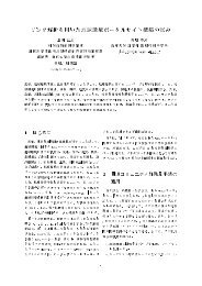
Figure 1: A diagrammatic representation of concurrent objects<br />
The major design issues of the KLIEG environment include the following:<br />
visual representations vs. textual representations<br />
design, programming, and debugging in the large on a relatively small screen<br />
a seamless integration of design, programming, and debugging processes.<br />
In the sequel, in Section 2 we discuss the benets of visual representations in objectbased<br />
parallel programming. Also in this section, we introduce the KLIEG language and<br />
propose the new programming methodology, that is, pattern-oriented visual programming.<br />
In Section 3 we briey review a support <strong>for</strong> visual design patterns provided by the KLIEG<br />
programming environment. In Section 4, we discuss scaling-up issues and introduce our<br />
approach based upon distorted multi-focus zooming techniques. We compare our work<br />
and related works in Section 5 and nally summaries the current status and the future<br />
direction of our work in Section 6.<br />
2 The <strong>Visual</strong> Language KLIEG and Pattern-Oriented<br />
<strong>Visual</strong> Programming<br />
2.1 Why Being <strong>Visual</strong><br />
As was briey mentioned in the previous chapter, diagrammatic representations of objectoriented<br />
programs or designs are better tted <strong>for</strong> human designers and programmers<br />
than the corresponding textual representations. This reason is simple and obvious: any<br />
<strong>for</strong>ms of textual representations of general graphs or networks invented so far are not as<br />
comprehensible as standard pictorial representations.<br />
In Figure 1, <strong>for</strong> instance, a typical diagrammatic representation of a collection of interrelated<br />
objects is illustrated. This gure represents a master-workers object network, in<br />
which a single master object dispatches tasks to multiple worker objects and gathers the<br />
results of the workers' computations. Either procedural or declarative, a textual representation<br />
of this sort of network is rather indirect and harder to understand. Notice that<br />
visual approaches in object-orientation are completely dierent from those approaches<br />
2
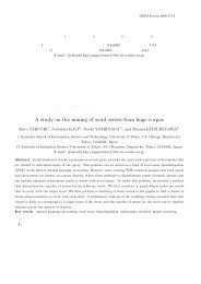
Figure 2: A producer-consumer pattern<br />
based on (structured) ow-charts: with a little computer support <strong>for</strong> syntax-directed<br />
editing and outline processing, syntax trees in a textual <strong>for</strong>m (i.e., ordinary programs)<br />
can be as comprehensible as those in a visual <strong>for</strong>m.<br />
2.2 Patterns in KLIEG<br />
<strong>Based</strong> upon the observation in the previous subsection, we design a visual (i.e., pictorial)<br />
language KLIEG <strong>for</strong> object-based parallel computing. Programs in the language<br />
KLIEG are depicted as visual data-ow diagrams and, in this respect, KLIEG is similar<br />
to CODE[PJ92] and Pictorial Janus[KMK90]. One of the signicant dierences is that<br />
KLIEG provides a support <strong>for</strong> visual patterns and pattern-oriented visual programming.<br />
2.2.1 Basic Usage<br />
A visual pattern in KLIEG is represented as an object data-ow diagram with abstract<br />
objects, which are called holes and to be instantiated later with concrete objects. In the<br />
KLIEG environment, a visual pattern can keep design and layout in<strong>for</strong>mation. The detail<br />
of this issue will be described in Section 3.<br />
Figure 2 is the rst and simple example of visual pattern, which represents the skeletal<br />
structure of producer-consumer object network. This pattern has two holes, that is, producer<br />
and consumer. In KLIEG, a recessed rectangle like producer or consumer represents<br />
a hole, which istobeinstantiated with a concrete object. In this gure, the producer hole<br />
has an output port Outs and the consumer has an input port Ins. In general, an input<br />
port is depicted recessed and an output port raised. These two ports are called output<br />
and input stream ports, meaning that they transmit and accept, respectively, streams of<br />
messages. The arrow connecting these two ports represents a communication channel or<br />
message stream.<br />
The KLIEG environmentprovides a support <strong>for</strong> denitions and use of visual patterns.<br />
For denitions of visual patterns, an editing interface similar to an draw editor is available.<br />
More advanced editing features including zooming supports will be introduced in<br />
Sections 3 and 4. For use of visual patterns, a drag-and-drop interface is provided. Holes<br />
of a pattern are instantiated with objects by dropping the icons representing the objects.<br />
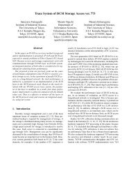
In Figure 3, the holes of producer are instantiated with two objectsnaturals and sum<br />
by dropping their icons onto the holes (Exactly speaking, each hole is instantiated with<br />
3
drag&drop<br />
Figure 3: Hole Instantiations by drag-and-dropping objects<br />
a copy of the object). In KLIEG, a raised round rectangle like naturals or sum is an<br />
iconic representation of an object, which depicts its signature or interface, i.e., the names<br />
and sorts of its ports. The intended behavior of this network is that, upon reception of<br />
the value N, naturals transmits 1 2:::N to sum, which in turn computes the value of<br />
1+2++ N and nally puts it on the port Sum.<br />
In this case, naturals has two ports N and Nats. N is an input port that accepts just a<br />
single message in its lifetime. This sort of port is called input singleton port and depicted<br />
as a recessed round rectangle. Similarly, Sum is an output port that transmits just a<br />
single message. This sort of port is called output singleton port and depicted as a raised<br />
round rectangle.<br />
As illustrated in Figure 3, the output stream port Nats of naturals and the input<br />
stream port Summands of sum are automatically connected via a message stream upon<br />
instantiation. This connection is made by matching Nats and Summands with Outs and<br />
Ins, respectively. In contrast, N and Sum cannot match any ports in the pattern. In<br />
general, the dropped object can have more ports than the hole to which it is dropped.<br />
The KLIEG environment calculates the most probable matching among ports of the<br />
object and the hole using the following in<strong>for</strong>mation of each port:<br />
whether singleton or stream<br />
whether input or output<br />
the types of messages received/transmitted on the port<br />
the geometry within a hole or an object.<br />
The rst two are obvious: a singleton port only matches another singleton port, and so<br />
on. The third in<strong>for</strong>mation is exploited by the type inference algorithm that is similar to<br />
the mode analysis algorithm[UM94] <strong>for</strong> an parallel logic programming language FGHC<br />
(Flat Guarded Horn Clauses). The last in<strong>for</strong>mation is conducted only when the other<br />
three are not sucient <strong>for</strong> resolution of ambiguities since it is heuristic in<strong>for</strong>mation and<br />
thus error-prone.<br />
In case of Figure 3, the rst two in<strong>for</strong>mation is sucient to get the correct result, i.e.,<br />
Outs of producer and Ins of consumer correspond to Nats of naturals and Summands of<br />
sum, respectively. Notice that the name of a port is ignored in this matching process.<br />
4
Figure 4: The interface and implementation of sum of<br />
Figure 5: A base pattern <strong>for</strong> master-workers<br />
2.2.2 Hierarchical Constructions<br />
Even with a pictorial representation, a large and at object network is rarely comprehensible.<br />
To overcome this diculty, the KLIEG language/environment provides a means <strong>for</strong><br />
hierarchical constructions of patterns and object networks.<br />
Firstly, an object in KLIEG can be dened hierarchically. Figure 4 illustrates a simple<br />
example: the small round rectangle sum of represents the interface of an object sum of<br />
the rest of the gure represents its body or implementation. That is, an object sum of<br />
consists of two objects naturals and sum that are embedded in the producer consumer<br />
pattern. Notice that this picture is regarded as a rewriting rule and so the KLIEG language<br />
processor reduces the interface of an object in a program into its implementation. Notice<br />
also that the KLIEG allows the programmer to describe visual conditional rewriting rules<br />
that are as expressive as clauses of a committed-choice parallel logic language Moded<br />
FGHC[UM94].<br />
Secondly, a visual pattern can be dened in a hierarchical manner. That is, by dropping<br />
a pattern onto a hole of another pattern, the hole can be instantiated with the <strong>for</strong>mer<br />
pattern. For instance, a master-workers network illustrated in Figure 1 can hierarchically<br />
be dened in KLIEG as follows:<br />
1. Dening the fundamental structure of the master-workers pattern<br />
Figure 5 depicts the basic structure of the master worker pattern, which has two<br />
holes, i.e., master and workers, andtwo arrows representing the communication<br />
channels between master and workers.<br />
2. Dening the master and workers patterns<br />
5
Figure 6: A master pattern<br />
Figure 7: A workers pattern<br />
The master and workers parts in Figure 5 should have theirown micro-architectures<br />
that are best described in terms of visual patterns. Figures 6 and 7 illustrate master<br />
and workers patterns in KLIEG, respectively. Since the master-workers pattern is a<br />
canonical example throughout this paper, we resume explanations of Figures 6 and<br />
7, later.<br />
3. Dropping patterns onto holes<br />
By dropping master and workers patterns in Figures 6 and 7 onto the corresponding<br />
holes of the master worker pattern in Figure 5, we get the master worker pattern in<br />
Figure 8.<br />
The master pattern in Figure 6 has three holes generator, dispatcher, andcombiner. Generator<br />
plays a role of generating tasks that will be delivered to workers. This part heavily<br />
depends on the problems to be solved and should often be replaced. Dispatcher receives<br />
tasks from generator and deliver each of them to an appropriate worker. Also it receives<br />
the computing results of workers and send them to combiner. By replacing dispatcher and<br />
combiner, the load balancing policy and the way tocombine the partial results, respectively,<br />
can be changed. The workers pattern is dened as a replication network, that is,<br />
workers includes a sequence of holes that are instantiated with copies of the same object.<br />
There<strong>for</strong>e, once a single worker hole is instantiated with an object, the other worker holes<br />
are automatically instantiated with its copies. The ellipsis \" in the sequence of worker<br />
holes means that the length of the sequence is not yet determined. It is determined in<br />
run-time by thenumber of messages received at the special port Wks, which is called a<br />
6
Figure 8: A master-workers pattern<br />
map port.<br />
Similar to Figure 3, a hierarchically constructed pattern can be used by dropping<br />
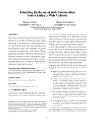
objects onto its holes. Figure 9 is an object network that is constructed of the masterworkers<br />
pattern and that computes the answers of the N-queens problem.<br />
2.3 Pattern-Oriented <strong>Visual</strong> Programming<br />
The KLIEG environment introduces a new programming methodology, that is, patternoriented<br />
visual programming, which is carried out as follows:<br />
1. Designers search <strong>for</strong> visual patterns in the pattern libraries. If any patterns appropriate<br />
<strong>for</strong> the application cannot be found, this step would be skipped.<br />
2. They construct new patterns that are suitable <strong>for</strong> describing the software architecture<br />
of the application from existing patterns or from scratch in a hierarchical<br />
manner.<br />
3. Programmers dene and/or search <strong>for</strong> objects with which holes of the patterns shall<br />
be instantiated.<br />
In other words, the software architecture of the application is rst dened and components<br />
of the architecture will be introduced later as replaceable elements in pattern-oriented<br />
visual programming. Also the architecture can be incrementally modiedby replacing<br />
component patterns (e.g., master and workers patterns in Section 2.2.2). Notice that the<br />
designers in the rst two stages are expected more experienced in design and programming<br />
than those programmers in the last stage.<br />
7
3 <strong>Visual</strong> Design Patterns<br />
Figure 9: An N-queens program<br />
Recently design patterns[GHJV95, Pre94] have been considered essential in design of exible<br />
and reusable object-oriented software. The notion of design pattern is also important<br />
in object-based parallel and distributed programming.<br />
The KLIEG environmentprovides a support <strong>for</strong> visual design patterns. In this section,<br />
we describe issues on supporting design patterns in object-based visual parallel programming<br />
environments.<br />
3.1 Design Patterns in an Instance-<strong>Based</strong> Programming Environment<br />
In our understanding, the signicance of design patterns is its supports <strong>for</strong> exible and<br />
reusable object-oriented software, that is, software that satises the following conditions:<br />
the software is constructed as a collection of objects<br />
in order to change some aspects or behaviors of the software, it is sucient to replace<br />
a small number of objects with those of the same roles.<br />
Notice that our understanding is rather instance-oriented or puts more emphasis on runtime<br />
structures of software. Some people might prefer more class-oriented views or to<br />
pay more attentions on the program structures. Often in practice, both instance-oriented<br />
and class-oriented views are used in software development processes:<br />
8
in the modeling stage, rst the application domain is modeled as a collection of<br />
inter-related objects<br />
in the design and coding stages, the program is created as a collection of class<br />
descriptions<br />
in the debugging stage, the debugger is used to capture ill-behaved objects.<br />
One of our goals is to design a seamlessly integrated visual programming environment in<br />
which all the stages above shall share the same notions and same visual abstractions.<br />
In general, concreteness, directness, and explicitness are important features of visual<br />
languages and thus instance-oriented approaches are more promising. In this paper, we<br />
show that our instance-oriented approach can be reasonable. For the purpose, we rst<br />
reconsider the notion of design patterns from the instance-oriented point of view. In this<br />
respect, essentially what design patterns provide are:<br />
coding techniques to make some objects easily replaceable so as to cope with changes<br />
of specications<br />
design in<strong>for</strong>mation including descriptions of design spaces and design decisions.<br />
The coding techniques provided by design patterns could be replaced with language mechanisms<br />
and/or environment supports, though they might be necessary <strong>for</strong> C++ programmers.<br />
The hole mechanism of KLIEG is suciently expressive and it can make objects<br />
and patterns replaceable (i.e., to make software exible). No more coding techniques are<br />
necessary.<br />
The real issue in this section is to provide a support <strong>for</strong> design in<strong>for</strong>mation by programming<br />
languages/environments. Design patterns are merely documents and there<strong>for</strong>e<br />
design in<strong>for</strong>mation is rarely available in run-time systems or programming environments.<br />
Furthermore, a signicantnumber of people consider that programming environmentsupports<br />
<strong>for</strong> design patterns are almost useless 1 .<br />
Given a specication change, the design in<strong>for</strong>mation that we consider signicant are<br />
those about:<br />
which objects shall be changed or replaced<br />
what are their alternatives<br />
how theybehave<br />
The rst piece of in<strong>for</strong>mation is obviously important. If reasonable alternatives are already<br />
available, the second in<strong>for</strong>mation is useful. Otherwise, the programmer(s) should learn<br />
the roles of the objects to be replaced and implement new alternatives. In this worst case,<br />
the last in<strong>for</strong>mation is useful.<br />
In our approach, these pieces of in<strong>for</strong>mation are respectively supported by the following<br />
manner:<br />
1 For instance, J. Vlissides listed ten misconceptions of patterns in [Vli97] and the fourth one was<br />
\Patterns need tool or methodological support to be eective."<br />
9
a visual pattern can have multiple aspects, each of which has its own layout in<strong>for</strong>mation<br />
by selecting an appropriate aspect, the objects to be replaced are displayed<br />
with emphasis.<br />
a hole in a visual pattern can keep more than one object, i.e., multiple implementations<br />
eachobjectinaholemay be regarded as default, sample, or alternative<br />
implementation<br />
the KLIEG tracer visualizes a computation using the layout in<strong>for</strong>mation of a visual<br />
pattern provided by its creator using the KLIEG editor.<br />
3.2 A Support <strong>for</strong> Multiple Aspects<br />
A hierarchically constructed pattern can become large and mayhave more than one aspect<br />
or behavior to be changed. For instance, it is desirable <strong>for</strong> the master worker pattern in<br />
Figure 8 to have the following aspects:<br />
the problem to be solved<br />
the load balancing policy<br />
the way tocombine the computed results by the workers.<br />
These three aspects are almost orthogonal, though in practice they can be inter-related.<br />
The KLIEG editor provides a multi-focus distorted zooming interface, called Mochi<br />
Sheet[TST + 97a], similar to the continuous zoom[BHDH95] in order eectively to display<br />
each aspect of a pattern. Figure 10 illustrates two aspects of the master-workers pattern.<br />
In the left diagram, holes related to the problem to be solved, i.e., generator and a worker,<br />
are magnied and other holes are shrunken. In this manner, holes and objects that should<br />
be instantiated and replaced are visually emphasized and so design in<strong>for</strong>mation concerning<br />
\which objects shall be changed" are eectively provided. In the right diagram, the<br />
objects related to \the way to combine computed results by the workers" are emphasized.<br />
The zooming interface is tightly embedded into the KLIEG editor. On one hand, the<br />
designer of a visual pattern can freely change the size and position of any visuals in the<br />
pattern and register any layout as a new aspect. On the other hand, a user of the pattern<br />
can choose any registered aspect with a dialog box. A change of the aspect is smoothly<br />
animated like morphing.<br />
3.3 A Support <strong>for</strong> Multiple Implementations<br />
In KLIEG, more than one object can be dropped onto a single hole of a visual pattern,<br />
or the hole can keep more than one object at a time. This mechanism is useful <strong>for</strong> the<br />
designer of a visual pattern to provide several kinds of implementations including:<br />
the default implementation that the user most likely to use<br />
sample implementations that tell the user the role of the hole<br />
alternative implementations that the user can choose and customize <strong>for</strong> building<br />
applications.<br />
10
Figure 10: Two aspects of the master-workers pattern<br />
The user of the pattern, on the other hand, can choose an appropriate implementation<br />
of a hole via a dialog box. If the default implementation is general enough, what a novice<br />
user normally does is just to choose it. With a sample implementation, the user can learn<br />
the basic role of the hole, possibly with a help of the KLIEG tracer that visualizes the<br />
behavior of the implementation. If a number of alternative implementations cover most<br />
areas of the design space, it is sucient tochoose the most eligible one.<br />
Notice that the KLIEG environment has not yet succeeded to eectively provide tradeo<br />
in<strong>for</strong>mation among those alternatives in a visual manner. Currently written documents<br />
are the only solution to this problem 2 .<br />
3.4 <strong>Visual</strong>izing Program Behaviors<br />
The KLIEG tracer visualizes and animates program execution. Figure 11 is a snapshot<br />
of the KLIEG tracer, which are currently executing the N-queens program dened in<br />
Figure 9. This picture automatically generated by the tracer is more or less similar to<br />
Figure 9: the relative positions and sizes of pass answers, dispatcher, andanumber of<br />
nqueen worker are almost the same. Notice that in this gure the generator has already<br />
nished its work and becomes a small rectangle on the top left of the master rectangle.<br />
The KLIEG tracer utilizes the layout in<strong>for</strong>mation of visual patterns during visualization.<br />
In case of Figure 11, <strong>for</strong> instance, this picture is generated with the layout<br />
in<strong>for</strong>mation of master worker pattern provided by its designer and without any optional<br />
in<strong>for</strong>mation. This visualization technique using layout in<strong>for</strong>mation of the visual program<br />
is similar to the one employed by Pictorial Janus[KMK90]. In addition, the KLIEG tracer<br />
2 Wehave a plan to extend Mochi Sheet to support hyper links.<br />
11
Figure 11: The KLIEG tracer<br />
has a unique feature: it is integrated with the KLIEG editor. The tracer also supports<br />
multiple aspects of a visual pattern and the user can interactively change its aspect during<br />
execution. For the purposes, the tracer also uses a multi-focus distorted zooming<br />
algorithm.<br />
4 Scaling-up Issues<br />
For a long time, visual languages have been considered only useful <strong>for</strong> toy problems or<br />
end users' programming. However, recent advancements of visual technologies can make<br />
visual languages more practical. The KLIEG environment provides zooming interfaces<br />
<strong>for</strong> the user to manipulate dataow diagrams that are too large to t in a single computer<br />
display ofatypical resolution (e.g., 1024 768). In this section, we demonstrate how the<br />
zooming interfaces are incorporated into the KLIEG environment.<br />
On one hand, a snapshot of a computation depicted by the KLIEG tracer is usually<br />
much larger than its corresponding source program. Even if a source program is small,<br />
the number of objects created during the execution can be large. There<strong>for</strong>e, the KLIEG<br />
tracer should provide a sophisticated browsing interface so that only the portions in<br />
considerations and their related contexts be displayed. Notice that not only visual but<br />
also textual tracers/debuggers developed so far rarely provide such sophisticated browsing<br />
interfaces.<br />
On the other hand, the KLIEG editor should support not only browsing but also<br />
editing. The zooming interfaces with editing are an important research area that most<br />
12
Figure 12: A zooming image of the KLIEG tracer<br />
people do not notice.<br />
4.1 The Zooming Interface of the KLIEG Tracer<br />
During execution of a KLIEG program with the tracer, the user can magnify any portions<br />
of the object dataow diagram generated by the program execution. For instance,<br />
by magnifying the nqueen gen and the leftmost nqueen worker in Figure 11, the user<br />
can get the image like Figure12. The KLIEG tracer employs the continuous zoom<br />
algorithm[BHDH95] and semantic zooming <strong>for</strong> this purpose.<br />
Although solely the continuous zoom algorithm usually works well, it sometimes fails.<br />
Atypical example is a SPMD (single program, multiple data streams) computation, in<br />
which anumber of objects of the same type work together in parallel. Their behaviors<br />
are essentially the same but they may have dierent data. If the number of the parallel<br />
objects becomes large (e.g., > 100), the continuous zoom algorithm allocates each object<br />
an equally small area like Figure 13, or otherwise it allocates suciently large spaces<br />
<strong>for</strong> a small number of xed objects. The point is that the continuous zoom algorithm<br />
is designed as domain-independent and does not assume any domain specic knowledge.<br />
It cannot well handle a large number of similar objects (or nodes) that share the same<br />
parent node in the hierarchy.<br />
Since SPMD computations often appear in practical settings, the KLIEG language and<br />
tracer provides a special support <strong>for</strong> them using domain specic in<strong>for</strong>mation. First, the<br />
KLIEG language provides the notion of replication pattern which represents a number of<br />
objects of the same type. An example usage of a replication pattern is already introduced<br />
in the workers pattern in Figure 7. Second, the KLIEG tracer provides a special browsing<br />
13
Figure 13: Normal zooming of a replication pattern<br />
Figure 14: Semantic zooming of a replication pattern<br />
facility <strong>for</strong> replication patterns. Namely,any object in a replication pattern can selectively<br />
be magnied and the details of the others can be omitted simultaneously. Omitted objects<br />
might be represented as \" and they still can be accessible bymoving the foci by mouse<br />
operations. Figure 14 illustrates an example of semantic zooming provided by the KLIEG<br />
tracer. This gure and the previous one depict the same snapshot of a computation with<br />
dierent zooming techniques.<br />
The reason why an object dataow diagram representing a snapshot of a computation<br />
can signicantly be larger than the source program is that sub-diagrams occurring in the<br />
source program can be copied many times during execution. Signicant parts of these<br />
copy processes can often be represented by replication patterns.<br />
4.2 The Zooming Interface of the KLIEG Editor<br />
A KLIEG program consists of one or more modules, each of which is a collection of<br />
object and pattern denitions. For instance, Figure 15 illustrates a program consisting of<br />
modules whose names are qsort, append, andprimes. Each module have small rectangles<br />
representing object interfaces, object implementations. In order to edit a program which<br />
is under development, the user rst magnies the portions that are soon to be edited<br />
and/or referenced. Figure 16 is a typical layout example, in which the qsort module is<br />
magnied.<br />
During an editing session, any visuals might be created or deleted. This means that<br />
the default position of each nodemightbechanged frequently during an editing session.<br />
Without some reasonable constraints, re-computation of the layout would take along<br />
time and it would be dicult to achieve interactive responses.<br />
Mochi Sheet [TST + 97a] that provides the zooming interface of the KLIEG editor<br />
assumes a simple constraints based on griding <strong>for</strong> rapid re-computation of the layout.<br />
This is the reason why modules and denitions in Figures 15 and 16 are regularly aligned.<br />
We consider that the griding constraint ofMochi Sheet is reasonable compromise between<br />
14
Figure 15: An initial image of the KLIEG editor<br />
Figure 16: Magnifying a module<br />
15
freedom of the layout and interactive responses.<br />
After each editing session, a typical user changes the layout of the program to her or<br />
his most familiar one. To support user's preferences of the default layout, Mochi Sheet<br />
provides a resize operation so that the previous layout can be quickly recovered by simple<br />
mouse operations. In addition, the history of the layouts are kept in the system and any<br />
of them can be also recovered by mouse operations.<br />
5 Related Work<br />
Until now, a lot of visual parallel programming languages have been proposed including<br />
CODE[PJ92] and Pictorial Janus[KMK90]. However, most of them do not provide any<br />
mechanism <strong>for</strong> replaceable objects or processes. There<strong>for</strong>e, it is dicult (or impossible)<br />
to explicitly dene reusable software architectures nor replaceable components in these<br />
languages.<br />
VISTA[SF94] is one of the exceptions and provides the notion of public processor.<br />
Although public processors in VISTA are replaced with other compatible processors, no<br />
design in<strong>for</strong>mation is available in the VISTA programming environment. In this respect,<br />
KLIEG provides a deeper support <strong>for</strong> pattern-oriented visual programming.<br />
For scaling up, VIPR recently introduced a sheye zooming interface[CS96]. Still,<br />
however, it supports only a single-focus zooming. In our experiences, multi-focus zooming<br />
is better suited in editing and debugging object-based visual parallel programs partly<br />
because, in editing and debugging, we oftenwould like to see the sender and the receiver<br />
objects simultaneously. Also, since KLIEG provides a support <strong>for</strong> multiple aspects of a<br />
visual pattern, a single-focus zooming interface is insucient <strong>for</strong> our purpose.<br />
6 Conclusion<br />
Currently, visual patterns in KLIEG can have the following in<strong>for</strong>mation of object-oriented<br />
parallel software:<br />
Design pattern in<strong>for</strong>mation <strong>for</strong> parallel and distributed software<br />
Layout in<strong>for</strong>mation of objects <strong>for</strong> software visualization.<br />
<strong>Visual</strong> patterns and supports <strong>for</strong> pattern-oriented visual programming in KLIEG integrate<br />
the design and coding stages of program development in a seamless manner. That is, both<br />
a program and its design in<strong>for</strong>mation are represented as the same collection of visual<br />
patterns and visual objects. There are no essential dierences between them.<br />
Layout in<strong>for</strong>mation in visual patterns are useful in particular in visual debugging. The<br />
KLIEG tracer animates a computation by generating successive images, each of which is<br />
a snapshot of the computation, using the layout in<strong>for</strong>mation of visual patterns provided<br />
by their designer(s). In this manner, almost the same pictorial images are available not<br />
only in the design and coding states but also in the debugging stage. This sort of seamless<br />
integration is important in visual programming environments.<br />
16
Our future work includes pattern-directed compilation technologies. For instance,<br />
since the master-workers pattern introduced in this paper implements a typical load balancing<br />
schema, it seems promising to attach to the pattern optional in<strong>for</strong>mation (e.g.,<br />
in<strong>for</strong>mation <strong>for</strong> analysis and code translation) <strong>for</strong> the compiler. That is, if the compiler<br />
can recognize the master-workers pattern in a program, it might be possible to generate<br />
better codes. For the purposes, we alsohave to consider visual representations of<br />
compile-time metalevel architectures.<br />
References<br />
[BHDH95] Lyn Bartram, Albert Ho, John Dill, and Frank Henigman. The Continuous<br />
Zoom: A Constrained Fisheye Technique <strong>for</strong> Viewing and Navigating Large<br />
In<strong>for</strong>mation Space. In Proceedings of UIST '95, pages 207{215, November<br />
1995.<br />
[Boo94]<br />
[CS96]<br />
[GHJV95]<br />
[KMK90]<br />
[PJ92]<br />
[Pre94]<br />
[RBP + 91]<br />
Grady Booch. <strong>Object</strong>-Oriented Analysis and Design with Applications, Second<br />
Edition. The Benjamin/Cummings Publishing, 1994.<br />
Wayne Citrin and Carlos Santiago. Incorporating sheying into a visual programming<br />
environment. In Proc. 1996 IEEE Symposium on <strong>Visual</strong> Languages,<br />
pages 20{27, 1996.<br />
Erich Gamma, Richard Helm, Ralph Johnson, and John Vlissides. Design<br />
Patterns { Elements of Reusable <strong>Object</strong>-Oriented Software. Addison-Wesley,<br />
1995.<br />
Vijay A.Saraswat Kenneth M. Kahn. Complete <strong>Visual</strong>izations of Concurrent<br />
Programs and their Executions. In Proc. 1990 IEEE Workshop on <strong>Visual</strong><br />
Languages, October 1990.<br />
P.Newton and J.C.Browne. The CODE 2.0 Graphical <strong>Parallel</strong> Programming<br />
Language. In Proc. ACM Int. Conf. on Supercomputing, July 1992.<br />
Wolfgang Pree. Design Patterns <strong>for</strong> <strong>Object</strong>-Oriented Software Development.<br />
Addison-Wesley, 1994.<br />
J. Rumbaugh, M. Blaha, W. Premerlani, F. Eddy, and W. Lorensen. <strong>Object</strong>-<br />
Oriented Modeling and Design. Prentice-Hall, 1991.<br />
[SF94] Stefan Schier and Joachim Hans Frohlich. Concepts and Architecture of<br />
Vista - a Multiparadigm Programming Environment. In Proc. 1994 IEEE<br />
Symposium on <strong>Visual</strong> Languages, 1994.<br />
[TST + 97a] M. Toyoda, B. Shizuki, S. Takahashi, , and E. Shibayama. Mochi sheet:<br />
Integration of zooming and layout editing. In Proceedings of Interaction'97,<br />
pages 79{86. In<strong>for</strong>mation Processing Society ofJapan,February 1997. (In<br />
Japanese).<br />
17
[TST + 97b] M. Toyoda, B. Shizuki, S. Takahashi, S. Matsuoka, and E. Shibayama. Supporting<br />
design patterns in a visual parallel data-ow programming environment.<br />
In IEEE Symposium on <strong>Visual</strong> Languages. IEEE, September 1997.<br />
[UM94] Kazunori Ueda and Morita Masao. Moded Flat GHC and Its Message-<br />
Oriented Implementation Technique. New Generation <strong>Computing</strong>, 13(1):3{43,<br />
1994.<br />
[Vli97] John Vlissides. Patterns: The top 10 misconceptions. <strong>Object</strong> Magazine, 1997.<br />
http://www.sigs.com/publications/docs/objm/9703/9703.vlissides.html.<br />
18