Eclipse ThermJet Burners - Power Equipment Company
Eclipse ThermJet Burners - Power Equipment Company
Eclipse ThermJet Burners - Power Equipment Company

You also want an ePaper? Increase the reach of your titles
YUMPU automatically turns print PDFs into web optimized ePapers that Google loves.
Installation Guide 205<br />
3/5/07<br />
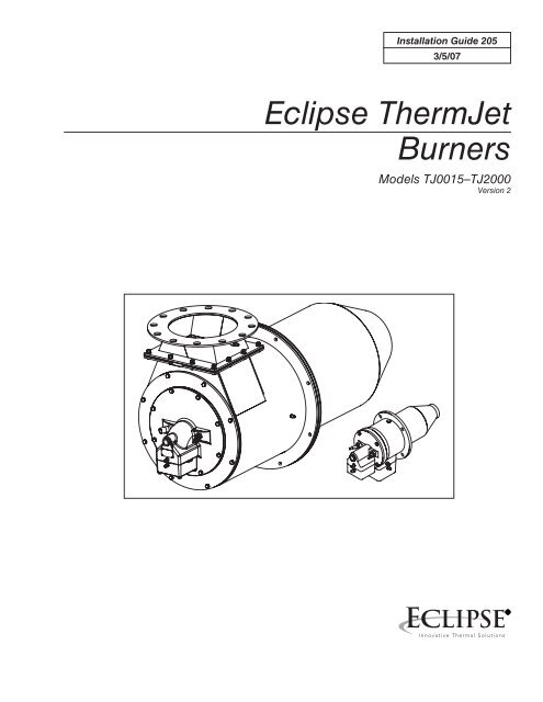
<strong>Eclipse</strong> <strong>ThermJet</strong><br />
<strong>Burners</strong><br />
Models TJ0015–TJ2000<br />
Version 2
Copyright<br />
Copyright 2007 by <strong>Eclipse</strong>, Inc. All rights reserved worldwide.<br />
This publication is protected by federal regulation and shall not<br />
be copied, distributed, transmitted, transcribed or translated<br />
into any human or computer language, in any form or by any<br />
means, to any third parties, without the express written consent<br />
of <strong>Eclipse</strong>, Inc.<br />
In accordance with the manufacturer’s policy of continual<br />
product improvement, the product presented in this brochure is<br />
subject to change without notice or obligation.<br />
Disclaimer Notice<br />
The material in this manual is believed adequate for the intended<br />
use of the product. If the product is used for purposes other<br />
than those specified herein, confirmation of validity and suitability<br />
must be obtained. <strong>Eclipse</strong> warrants that the product itself<br />
does not infringe upon any United States patents. No further<br />
warranty is expressed or implied.<br />
We have made every effort to make this manual as accurate<br />
and complete as possible. Should you find errors or omissions,<br />
please bring them to our attention so that we may correct<br />
them. In this way we hope to improve our product documentation<br />
for the benefit of our customers. Please send your corrections<br />
and comments to our Marketing Communications<br />
Manager.<br />
Liability and<br />
Warranty<br />
It must be understood that <strong>Eclipse</strong>’s liability for its product,<br />
whether due to breach of warranty, negligence, strict liability,<br />
or otherwise is limited to the furnishing of replacement parts<br />
and <strong>Eclipse</strong> will not be liable for any other injury, loss, damage<br />
or expenses, whether direct or consequential, including but not<br />
limited to loss of use, income, or damage to material arising in<br />
connection with the sale, installation, use of, inability to use, or<br />
the repair or replacement of <strong>Eclipse</strong>’s products.<br />
Any operation expressly prohibited in this Guide, any adjustment,<br />
or assembly procedures not recommended or authorized<br />
in these instructions shall void the warranty.<br />
<strong>Eclipse</strong> <strong>ThermJet</strong> v2, Installation Guide No. 205, 3/5/07
About this manual<br />
Audience<br />
This manual has been written for people who are already<br />
familiar with all aspects of a nozzle-mix burner and its add-on<br />
components, also referred to as “the burner system.”<br />
These aspects are:<br />
•<br />
•<br />
•<br />
Installation<br />
Use<br />
Maintenance<br />
The audience is expected to have had previous experience with<br />
this kind of equipment.<br />
<strong>ThermJet</strong> Documents<br />
Installation Guide No. 205<br />
• This document<br />
Data Sheet No. 205-1 through 205-13<br />
• Available for individual TJ models<br />
• Required to complete installation<br />
Design Guide No. 205<br />
• Used with Data Sheet to design burner system<br />
Price List No. 205<br />
• Used to order burners<br />
Related Documents<br />
•<br />
•<br />
EFE 825 (Combustion Engineering Guide)<br />
<strong>Eclipse</strong> bulletins and Info Guides:<br />
610, 710, 720, 730, 742, 744, 760, 930, I-354.<br />
Purpose<br />
The purpose of this manual is to make sure that you carry out<br />
the installation of a safe, effective and trouble-free combustion<br />
system.<br />
<strong>Eclipse</strong> <strong>ThermJet</strong> v2, Installation Guide No. 205, 3/5/07
Document<br />
Conventions<br />
There are several special symbols in this document. You must<br />
know their meaning and importance.<br />
The explanation of these symbols follows below. Please read it<br />
thoroughly.<br />
Danger:<br />
Indicates hazards or unsafe practices which<br />
WILL result in severe personal injury or even<br />
death.<br />
Only qualified and well trained personnel are<br />
allowed to carry out these instructions or procedures.<br />
Act with great care and follow the instructions.<br />
Warning:<br />
Indicates hazards or unsafe practices which could<br />
result in severe personal injury or damage.<br />
Act with great care and follow the instructions.<br />
Caution:<br />
Indicates hazards or unsafe practices which could result in<br />
damage to the machine or minor personal injury, act carefully.<br />
Note:<br />
Indicates an important part of the text. Read thoroughly.<br />
How to Get Help<br />
If you need help, contact your local <strong>Eclipse</strong> representative. You<br />
can also contact <strong>Eclipse</strong> at:<br />
1665 Elmwood Rd.<br />
Rockford, Illinois 61103 U.S.A.<br />
Phone: 815-877-3031<br />
Fax: 815-877-3336<br />
http://www.eclipsenet.com<br />
<strong>Eclipse</strong> <strong>ThermJet</strong> v2, Installation Guide No. 205, 3/5/07
Table of contents<br />
1<br />
2<br />
3<br />
4<br />
Introduction<br />
Product.................................................................................................7<br />
Description..........................................................................................7<br />
Figure 1.1 The <strong>ThermJet</strong> Burner......................................................7<br />
Safety<br />
Introduction.........................................................................................8<br />
Safety.....................................................................................................8<br />
Capabilities .........................................................................................9<br />
Operator Training...............................................................................9<br />
Replacement Parts.............................................................................9<br />
Installation<br />
Introduction.........................................................................................10<br />
Handling and Storage.........................................................................10<br />
Position of Components...................................................................10<br />
Approval of Components.................................................................10<br />
Checklist Before Installation............................................................12<br />
Prepare The Burner...........................................................................13<br />
Burner Installation..............................................................................15<br />
Figure 3.2: Firing Tubes and<br />
Combustion Blocks – Installation.............................................15<br />
Piping Installation................................................................................16<br />
Valve Installation.................................................................................17<br />
Checklist After Installation...............................................................18<br />
Prepare for Adjustment.....................................................................18<br />
Adjustment, Start & Stop<br />
Introduction.........................................................................................19<br />
Modulating Gas and Air Ratio System...........................................19<br />
Step 1: Reset the system...................................................................19<br />
Step 3: Set low fire air......................................................................21<br />
Step 4: Verify the air settings............................................................21<br />
Step 5: Ignite the burners.................................................................21<br />
Step 6: Set high fire gas .....................................................................22<br />
Step 7: Set low fire gas......................................................................22<br />
Step 8: Verify the gas settings...........................................................23<br />
<strong>Eclipse</strong> <strong>ThermJet</strong> v2, Installation Guide No. 205, 3/5/07
Fixed-air system ................................................................................23<br />
Step 1: Reset the system..................................................................23<br />
Step 2: Set high fire air.....................................................................23<br />
Step 3: Ignite the burners................................................................24<br />
Step 4: Set high fire gas...................................................................25<br />
Step 5: Set low fire gas....................................................................26<br />
Step 6: Verify the gas settings.........................................................26<br />
Set the bypass pilot gas (optional).................................................26<br />
Start Procedure.................................................................................27<br />
Stop Procedure..................................................................................27<br />
5<br />
Maintenance & Troubleshooting<br />
Introduction........................................................................................28<br />
Monthly Checklist.............................................................................28<br />
Yearly Checklist.................................................................................29<br />
Troubleshooting Guide....................................................................30<br />
Appendix<br />
Conversion Factors ..........................................................................33<br />
Illustrated Parts List..........................................................................34<br />
<strong>ThermJet</strong> Illustrated Parts Drawing<br />
(Models TJ0015 through TJ1000).............................................35<br />
<strong>ThermJet</strong> Illustrated Parts Drawing<br />
(Models TJ1500 and TJ2000).....................................................36<br />
<strong>ThermJet</strong> Illustrated Parts List (Repeated)..................................37<br />
<strong>Eclipse</strong> <strong>ThermJet</strong> v2, Installation Guide No. 205, 3/5/07
Introduction<br />
1<br />
Product<br />
Description<br />
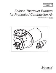
The <strong>ThermJet</strong> is a nozzle-mix burner that is designed to fire an<br />
intense stream of hot gases through a combustor using ambient<br />
combustion air.<br />
The high velocity of the gases improves temperature uniformity,<br />
product quality and system efficiency.<br />
The <strong>ThermJet</strong> burner comes in two types:<br />
• High Velocity (HV)<br />
• Medium Velocity (MV)<br />
The gas velocity can be as high as 500 ft/s for the High Velocity<br />
burner, and 250 ft/s for the Medium Velocity burner.<br />
Figure 1.1 The <strong>ThermJet</strong> Burner<br />
<strong>Eclipse</strong> <strong>ThermJet</strong> v2, Installation Guide No. 205, 3/5/07
Safety<br />
2<br />
Introduction<br />
Safety<br />
In this section you will find important notices about safe operation<br />
of a burner system. Read this entire manual before you<br />
attempt to start the system. If you do not understand any part<br />
of the information in this manual, then contact your local <strong>Eclipse</strong><br />
representative or <strong>Eclipse</strong> before you continue.<br />
Danger:<br />
The burners covered in this manual are designed<br />
to mix fuel with air and burn the resulting mixture.<br />
All fuel burning devices are capable of producing<br />
fires and explosions when improperly applied,<br />
installed, adjusted, controlled or maintained<br />
Do not bypass any safety feature. You can cause<br />
fires and explosions.<br />
Never try to light the burner if the burner shows<br />
signs of damage or malfunctioning.<br />
Warning:<br />
The burner is likely to have HOT surfaces. Always<br />
wear protective clothing when approaching<br />
the burner.<br />
Note:<br />
This manual gives information for the use of these burners<br />
for their specific design purpose. Do not deviate from any<br />
instructions or application limits in this manual without written<br />
advice from <strong>Eclipse</strong>.<br />
<strong>Eclipse</strong> <strong>ThermJet</strong> v2, Installation Guide No. 205, 3/5/07
Safety (Continued)<br />
Capabilities<br />
Operator Training<br />
Replacement Parts<br />
Warning:<br />
<strong>Eclipse</strong> products are designed to minimize the<br />
use of materials that contain crystalline silica.<br />
Examples of these chemicals are: respirable<br />
crystalline silica from bricks, cement or other<br />
masonry products and respirable refractory<br />
ceramic fibers from insulating blankets, boards,<br />
or gaskets. Despite these efforts, dust created by<br />
sanding, sawing, grinding, cutting, and other construction<br />
activities could release crystalline silica.<br />
Crystalline silica is known to cause cancer, and<br />
health risks from the exposure to these chemicals<br />
vary depending on the frequency and length<br />
of exposure to these chemicals. To reduce this<br />
risk, limit exposure to these chemicals, work in a<br />
well-ventilated area and wear approved personal<br />
protective safety equipment for these chemicals.<br />
Adjustment, maintenance and troubleshooting of the mechanical<br />
and the electrical parts of this system should be done by qualified<br />
personnel with good mechanical aptitude and experience<br />
with combustion equipment.<br />
The best safety precaution is an alert and competent operator.<br />
Thoroughly instruct new operators so they demonstrate<br />
an adequate understanding of the equipment and its operation.<br />
Regular retraining must be scheduled to maintain a high degree<br />
of proficiency.<br />
Order replacement parts from <strong>Eclipse</strong> only. Any customer-supplied<br />
valves or switches should carry UL, FM, CSA,CGA and/or<br />
CE approval where applicable.<br />
<strong>Eclipse</strong> <strong>ThermJet</strong> v2, Installation Guide No. 205, 3/5/07
Installation<br />
3<br />
Introduction<br />
Handling and<br />
Storage<br />
In this section you will find the information and instructions<br />
needed to install the burner and system components.<br />
Handling<br />
1. Make sure the area is clean.<br />
2. Protect the components from weather, damage, dirt and moisture.<br />
3. Protect the components from excessive temperatures and humidity.<br />
Storage<br />
1. Make sure the components are clean and free of damage.<br />
2. Store the components in a cool, clean, dry room.<br />
3. After making sure everything is present and in good condition,<br />
keep the components in original packages as long as possible.<br />
Position of<br />
Components<br />
Approval of<br />
Components<br />
The position and amount of components are determined by the<br />
kind of control method chosen. All the control methods can be<br />
found in Design Guide 205, Chapter 3 “System Design.” Use<br />
the schematics in that chapter to build your system.<br />
Limit controls and safety equipment<br />
All limit controls and safety equipment must comply with the<br />
current following standards:<br />
•<br />
•<br />
•<br />
•<br />
•<br />
•<br />
•<br />
NFPA Standard 86<br />
NFPA Standard 86C<br />
UL<br />
FM<br />
CGA<br />
EN 746-2<br />
All applicable local codes and/or standards<br />
10 <strong>Eclipse</strong> <strong>ThermJet</strong> v2, Installation Guide No. 205, 3/5/07
Approval of<br />
Components<br />
(Continued)<br />
Electrical wiring<br />
All the electrical wiring must comply with one of these<br />
standards:<br />
•<br />
•<br />
NFPA Standard 70<br />
ANSI-CI1981<br />
EN 746-2<br />
•<br />
The electrical wiring must also be acceptable to the local<br />
authority having jurisdiction.<br />
Gas Piping<br />
All the gas piping must comply with one of these standards:<br />
• NFPA Standard 54<br />
• ANSI Z223<br />
• EN 746-2<br />
The gas piping must also be acceptable to the local authority<br />
with jurisdiction.<br />
Where To Get the Standards<br />
The NFPA Standards are available from:<br />
National Fire Protection Agency<br />
Batterymarch Park<br />
Quincy, MA 02269<br />
The ANSI Standards are available from:<br />
American National Standard Institute<br />
1430 Broadway<br />
New York, N Y 10018<br />
The UL Standards are available from:<br />
333 Pfingsten Road<br />
Northbrook, IL 60062<br />
The FM Standards are available from:<br />
1151 Boston-Providence Turnpike<br />
P.O.Box 9102<br />
Norwood, MA 02062<br />
The CGA Standards are available from:<br />
55 Scarsdale Road<br />
Toronto, Ontario<br />
Canada M3B 2R3<br />
Information on the EN standards and where to get them is available from:<br />
Comité Européen de Normalisation<br />
Stassartstraat 36<br />
B-1050 Brussels<br />
Phone: +32-25196811<br />
Fax: +32-25196819<br />
Comité Européen de Normalisation Electronique<br />
Stassartstraat 36<br />
B-1050 Brussels<br />
Phone: +32-25196871<br />
Fax: +32-25196919<br />
<strong>Eclipse</strong> <strong>ThermJet</strong> v2, Installation Guide No. 205, 3/5/07<br />
11
Checklist Before<br />
Installation<br />
Intake<br />
To admit fresh combustion air from outdoors, provide an opening<br />
in the room of at least one square inch per 4000 Btu/hr.<br />
If there are corrosive fumes or materials in the air, then supply<br />
the burner with clean air from an uncontaminated area.<br />
Exhaust<br />
Do not allow exhaust gases to accumulate in the work area.<br />
Provide some positive means for exhausting them from the<br />
furnace and the building.<br />
Access<br />
Make sure that you install the burner in such a way that you can<br />
get easy access for inspection and maintenance.<br />
Environment<br />
Make sure that the local environment matches the original operating<br />
specifications. Check the following items:<br />
•<br />
•<br />
•<br />
•<br />
•<br />
Voltage, frequency and stability of the electrical power<br />
Type and supply pressure of the fuel<br />
Availability of enough fresh, clean combustion air<br />
Humidity, altitude and temperature of air<br />
Presence of damaging corrosive gases in the air<br />
12 <strong>Eclipse</strong> <strong>ThermJet</strong> v2, Installation Guide No. 205, 3/5/07
Prepare The Burner<br />
Several components must be installed to a burner before it can<br />
operate. Installation instructions follow:<br />
It is possible to change the relative position of the gas inlet with<br />
respect to the air inlet. This can be convenient for the routing of<br />
the piping.<br />
Rotate the rear cover (optional)<br />
To rotate the rear cover, do the following:<br />
1. Disconnect the piping at a union in the piping or the inlet<br />
flanges 1 provided on the burner.<br />
Note:<br />
Be careful not to lose or damage the orifice plate or the<br />
O-rings.<br />
1<br />
2<br />
3<br />
4<br />
2.<br />
3.<br />
Remove the four bolts 2.<br />
Remove the rear cover 3 from the burner housing 4.<br />
4<br />
4. Rotate the rear cover 3 to the position that you want.<br />
5. Put the rear cover in position against the burner housing 4.<br />
6. Install the four bolts 2.<br />
2<br />
3<br />
7. Reconnect the piping. Make sure that the O-rings show no<br />
signs of damage.<br />
<strong>Eclipse</strong> <strong>ThermJet</strong> v2, Installation Guide No. 205, 3/5/07<br />
13
Flame sensor<br />
Spark plug<br />
Installing The Flame Sensor<br />
1. Install the flame sensor into the 1/2” NPT opening in the<br />
rear cover.<br />
2. Make sure that you connect the flame sensor of a burner to<br />
the electrical circuit of that burner.<br />
Danger:<br />
If you connect the flame sensor of a burner to<br />
the electrical circuit of the wrong burner, then<br />
you can cause fires and explosions.<br />
There are two different types of flame sensors:<br />
Flame sensor;<br />
90º UV scanner<br />
UV Scanner<br />
For detailed information on how to install and connect a UV<br />
scanner, refer to:<br />
•<br />
•<br />
•<br />
Bulletin/Info Guide 854 for straight UV scanners<br />
Bulletin/Info Guide 852 for 90º UV scanners<br />
Bulletin/Info Guide 856 for self-check UV scanners.<br />
Flame Rod:<br />
Note:<br />
Only specific burner sizes with alloy or silicon carbide combustors<br />
can use a flame rod (see specific burner data sheets).<br />
Flame sensor;<br />
Flame rod<br />
For detailed information on how to install and connect a flame<br />
rod, refer to Bulletin/Info guide 832.<br />
Installing the spark plug<br />
Install the spark plug into the opening in the rear cover.<br />
Spark plug<br />
Note:<br />
Do not apply any grease to the threads of the spark plug.<br />
You can cause bad grounding of the spark plug if you apply<br />
grease to it. Bad grounding of the spark plug results in a<br />
weak spark.<br />
14 <strong>Eclipse</strong> <strong>ThermJet</strong> v2, Installation Guide No. 205, 3/5/07
Burner<br />
Installation<br />
Dimensions<br />
The burner attaches to the wall of the chamber with bolts<br />
through holes “C”. For full information on the dimensions, refer<br />
to specific data sheets.<br />
Figure 3.1 Burner attachment<br />
“C”<br />
Chamber wall<br />
Make sure that the wall of the chamber is strong enough to<br />
carry the weight of the burner. If necessary, reinforce the area<br />
where you plan to install the burner to support the weight of<br />
the burner.<br />
Avoid losses<br />
To make sure that heat does not go back to the casing of the<br />
chamber, it is important that the radial clearance around the firing<br />
tube is filled with ceramic fiber.<br />
Figure 3.2 Firing Tubes and Combustion Blocks – Installation<br />
➊<br />
➋<br />
➍<br />
➏<br />
➊<br />
➋<br />
➍<br />
➎<br />
➌<br />
Alloy<br />
1. Make sure the gasket ➊ is installed between<br />
the burner and the chamber wall ➋.<br />
2. Make sure that gasket ➊ does not leak.<br />
3. Check the size of the clearance. If the gap ➌<br />
around the firing tube is larger than 1/2”,<br />
then pack the gap with ceramic fiber ➍, as<br />
stated above.<br />
Silicon Carbide<br />
1. Make sure the gasket ➊ is installed between<br />
the burner flange and chamber wall ➋.<br />
2. Make sure that gasket ➎ is installed between<br />
SiC tube and flange ➏.<br />
3. Make sure neither gasket ➊ nor ➎ leaks.<br />
4. Check the size of the clearance. If the gap<br />
around the firing tube is larger than 1/2”,<br />
then pack the gap with ceramic fiber ➍, as<br />
stated above.<br />
<strong>Eclipse</strong> <strong>ThermJet</strong> v2, Installation Guide No. 205, 3/5/07<br />
15
Figure 3.2: Firing Tubes and Combustion Blocks – Installation (Continued)<br />
4<br />
1<br />
7<br />
8<br />
⓫<br />
Refractory Block<br />
1.<br />
2.<br />
3.<br />
Be sure the gasket 1 is installed between the burner 4 and<br />
the block holder 7.<br />
Be sure the gasket 8 is installed between the block holder<br />
7 and the chamber wall 2.<br />
Support the weight of the refractory block 9 with hard<br />
brick work ❿ Fill space around the block 9 with soft<br />
gasket material ⓫.<br />
2<br />
9 ❿<br />
Vertical Down Firing Blocks<br />
1. Down firing blocks may be suspended by customer-supplied<br />
hangers 2 attached to the burner body mounting bolts.<br />
2. Hangers should be attached to structural support 1.<br />
Piping Installation<br />
Layout<br />
Install the piping as shown in the schematics. Refer to Chapter 3<br />
of the <strong>ThermJet</strong> Design Guide No. 205.<br />
Pipe<br />
Union<br />
Bracket<br />
Support the piping<br />
Use brackets or hangers to support the gas piping. If you have<br />
questions, consult your local gas company.<br />
Straight run of pipe before a metering orifice<br />
Note:<br />
There must be a run of pipe with a straight length of at least<br />
10 pipe diameters before the burner metering orifice. If you<br />
do not do this, the pressure readings will be inaccurate.<br />
Pipe connections<br />
1. Install a pipe union in the gas line to the burner. This simplifies<br />
removal of the burner.<br />
2. The use of flexible pipe nipples in the gas line to the burner<br />
is optional. Flexible nipples can absorb stress due to heat<br />
expansion and slight misalignment.<br />
Note:<br />
Flexible pipe nipples will cause inaccurate metering orifice<br />
readings and may cause higher pressure drops than equivalent<br />
standard pipe. Consider this when you size the gas lines.<br />
Avoid large pressure drops<br />
Note:<br />
The pressure drop of the gas in the piping is a critical<br />
parameter. Make sure that the size of all the piping is large<br />
enough to prevent excessive pressure losses.<br />
16 <strong>Eclipse</strong> <strong>ThermJet</strong> v2, Installation Guide No. 205, 3/5/07
Valve Installation<br />
Valve orientation<br />
Install all the valves in such a way that the arrow (if present) on<br />
the valve body points in the direction of flow.<br />
Gas cocks<br />
Make sure that the handle of a gas cock is at a right angle to the<br />
valve body when the valve is in the closed position. This is an<br />
important position indicator. If you do not do this, somebody<br />
may think that the gas cock is in the closed position, while it is<br />
actually in the open position.<br />
Gas balancing valves<br />
A gas balancing valve is typically the same as a manual butterfly<br />
valve. For more information, refer to the section below.<br />
Manual butterfly valves<br />
1. Install manual butterfly valves in accordance with Bulletin/<br />
Info Guide 720.<br />
2. Install manual butterfly valves in the gas line to the burner<br />
(optional).<br />
Note:<br />
It is recommended that there is a run of pipe with a length<br />
of at least 10 pipe diameters between any flow altering<br />
device and the metering orifice on the burner.<br />
Automatic butterfly valve<br />
An automatic butterfly is driven by an actuator (actuator and<br />
mounting bracket not illustrated). Install the control valve in accordance<br />
with Bulletin/Info Guide 720.<br />
Ratio regulator<br />
• Connect an impulse line to the ratio regulator and to the<br />
air supply line.<br />
• Install the ratio regulator in accordance with Bulletin/Info<br />
Guide 742.<br />
CRS valve<br />
Install the CRS valve in accordance with Bulletin/Info Guide 744.<br />
<strong>Eclipse</strong> <strong>ThermJet</strong> v2, Installation Guide No. 205, 3/5/07<br />
17
Checklist After<br />
Installation<br />
Prepare for<br />
Adjustment<br />
To verify proper system installation, do the following:<br />
1. Make sure that there are no leaks in the gas lines and the air<br />
lines.<br />
2. Make sure all the components of the flame monitoring control<br />
system are properly installed. This includes verifying that<br />
all switches are installed in correct locations and all wiring,<br />
pressure and impulse lines are properly connected.<br />
3. Make sure components of spark ignition system are installed<br />
and functioning properly.<br />
4. Make sure that the blower rotates in the correct direction. If<br />
incorrect, then have a qualified electrician rewire the blower<br />
to reverse its rotation.<br />
5. Make sure all valves are installed in proper location and correctly<br />
oriented relative to the gas or air flow direction.<br />
After installation of the burner system components is complete,<br />
the following steps should be followed in order to prepare for<br />
adjustment:<br />
1.<br />
2.<br />
3.<br />
4.<br />
5.<br />
6.<br />
Set the air pressure switch so that it drops out at 4” w.c. (10<br />
mbar) below the pressure rating of the blower.<br />
Set the low gas pressure switch at 4” w.c. (10 mbar) below the<br />
gas pressure measured at the inlet to the main gas valve train.<br />
Set the high gas pressure switch so that it comes on at 4” w.c.<br />
(10 mbar) above the gas pressure measured at the inlet to the<br />
main gas valve train.<br />
Close all the burner gas cocks.<br />
Try to light a burner before the purge and other timers have<br />
finished their cycles. Make sure that the flame monitoring system<br />
indicates a flame failure.<br />
Trip out pressure switches and other limit interlocks. Make<br />
sure that the main gas valve train closes.<br />
Danger:<br />
If simulated limits or simulated flame failures<br />
do not shut down the fuel system within the<br />
required failure response time, immediately correct<br />
the problem before proceeding.<br />
18 <strong>Eclipse</strong> <strong>ThermJet</strong> v2, Installation Guide No. 205, 3/5/07
Adjustment, Start & Stop<br />
4<br />
Introduction<br />
In this chapter you will find instructions on how to adjust a<br />
system, and how to start and stop a system. The chapter starts<br />
with general instructions that are useful for adjustment.<br />
Danger<br />
Do not bypass any safety feature. You can cause<br />
fires and explosions.<br />
Obey the safety precautions in Chapter 2.<br />
Adjustment<br />
There are two adjustment procedures. To adjust a modulating<br />
gas and air ratio system, refer to “Modulating Gas and Air Ratio<br />
System” on page 18. For a fixed-air system, refer to “Fixed-air<br />
System” on page 22.<br />
Modulating Gas<br />
and Air Ratio<br />
System<br />
If you adjust an on-ratio system for the first time, you must<br />
follow these steps (Refer to Figure 3.1 and Figure 3.3 in the<br />
<strong>ThermJet</strong> Design Guide No. 205):<br />
1.<br />
2.<br />
3.<br />
4.<br />
5.<br />
6.<br />
7.<br />
8.<br />
Reset the system<br />
Set high fire air<br />
Set low fire air<br />
Verify the air settings<br />
Ignite the burners<br />
Set high fire gas<br />
Set low fire gas<br />
Verify the gas settings.<br />
Step 1: Reset the system<br />
1.<br />
2.<br />
Close these valves: the automatic gas valves and the gas cocks.<br />
Fully open the manual air butterfly valve at each burner.<br />
a. Drive the automatic zone air control valve to high fire.<br />
b. Adjust the automatic zone air control valve so that it is<br />
fully open. The automatic zone air control valve can be<br />
either a butterfly valve or a CRS valve.<br />
<strong>Eclipse</strong> <strong>ThermJet</strong> v2, Installation Guide No. 205, 3/5/07<br />
19
3.<br />
Start the blower.<br />
Caution<br />
Make sure that the blower rotates in the correct direction. If<br />
incorrect, have a qualified electrician rewire the blower to<br />
reverse its rotation.<br />
1.<br />
2.<br />
3.<br />
Set the system to high fire, but DO NOT ignite the<br />
burner(s).<br />
Use the air curves from the appropriate <strong>ThermJet</strong> Data<br />
Sheet to find the differential air pressure needed at high fire.<br />
This is now the target value for high fire.<br />
Set high fire air.<br />
Tap A<br />
Manometer<br />
tap C<br />
Note<br />
A pressure tap is open when the screw inside the tap is<br />
unscrewed approximately half a turn.<br />
To set high fire air on a single burner system:<br />
a. Make sure that pressure taps A and C are open.<br />
b. Connect the manometer to taps A and C (across the<br />
air orifice).<br />
c. Adjust the manual butterfly valve until the high-fire differential<br />
air pressure is at the target value.<br />
d. Remove the manometer.<br />
e. Close the pressure taps.<br />
To set high fire air on a multiple burner system:<br />
a. Make sure that pressure taps A and C of the first burner<br />
are open.<br />
b. Connect the manometer to taps A and C of the first<br />
burner (across the air orifice).<br />
c. Adjust the zone air manual butterfly valve to achieve the<br />
target value for the first burner.<br />
d. Measure and note the differential air pressure across the<br />
next burner in the zone.<br />
e. Repeat d for all the other burners in the zone (if any).<br />
f. If all the measured differential pressures are within 0.3”<br />
w.c. (0.75 mbar) of each other, then proceed to the next<br />
section. If the variation is greater than 0.3” w.c. (0.75<br />
mbar) it will be necessary to adjust the manual air butterfly<br />
valve at each burner to improve the balance.<br />
g. Make sure that all the pressure taps are closed.<br />
4.<br />
Repeat 3. for other zones (if any).<br />
20 <strong>Eclipse</strong> <strong>ThermJet</strong> v2, Installation Guide No. 205, 3/5/07
Step 3: Set low fire air<br />
1.<br />
2.<br />
3.<br />
4.<br />
Set the system to low fire.<br />
Connect the manometer to tap A (air inlet pressure tap).<br />
Adjust the automatic zone air control valve until the lowfire<br />
static air pressure is 0.2” w.c. This is the initial setting<br />
only. Further adjustment may be required.<br />
Repeat 2 and 3 for the other zones (if any).<br />
Step 4: Verify the air settings<br />
Step 5: Ignite the burners<br />
Make sure all the settings are still the same after you cycle the<br />
system several times between high and low fire.<br />
Warning:<br />
This procedure assumes that a flame monitoring<br />
control system is installed and is serviceable. It also<br />
assumes that normal low fire start is being used.<br />
If low fire gas is too low to be used for ignition,<br />
refer to options in “Set the bypass pilot gas (optional)”<br />
on page 25.<br />
1.<br />
2.<br />
3.<br />
4.<br />
5.<br />
6.<br />
7.<br />
8.<br />
9.<br />
10.<br />
11.<br />
Drive the zone air automatic control valve to low fire.<br />
Make sure the combustion air blower is running.<br />
Set the manual gas butterfly valve at each burner to 50% open.<br />
Set the adjusting screw on the ratio regulator six full (360°)<br />
turns down from the top (initial setting).<br />
Open zone manual gas cock.<br />
Open manual gas cock at each burner.<br />
Initiate the ignition sequence through the flame monitoring<br />
control system.<br />
a.<br />
b.<br />
Check that all the burners in the zone have ignited.<br />
If safety shut-off solenoid valves are installed at each burner,<br />
then repeat 6 and 7 for all the burners in the zone.<br />
If all the burners have ignited, drive the zone air butterfly<br />
valve to high fire. Verify flame is present at each burner. If<br />
burners do not light, add a 1/2 turn down on the proportionator,<br />
repeat steps 7 through 11.<br />
Verify that air pressure drops have remained the same.<br />
If air pressure drop is too high, close down the zone manual<br />
air butterfly valve.<br />
If air pressure drop is too low, open the zone manual air<br />
butterfly valve.<br />
<strong>Eclipse</strong> <strong>ThermJet</strong> v2, Installation Guide No. 205, 3/5/07<br />
21
Step 6: Set high fire gas<br />
tap D<br />
tap B<br />
Manometer<br />
Step 7: Set low fire gas<br />
1.<br />
2.<br />
3.<br />
4.<br />
5.<br />
6.<br />
1.<br />
2.<br />
3.<br />
4.<br />
Use the gas curve from the appropriate <strong>ThermJet</strong> Data Sheet<br />
for the gas being used to find the differential gas pressure<br />
needed at high fire. This is the target value for high fire.<br />
Connect the manometer to taps B and D (across the gas orifice).<br />
Measure the high fire differential gas pressure for the first<br />
burner.<br />
Adjust the gas butterfly valve at the burner until the gas<br />
flow is at the target value.<br />
Repeat 3 thru 4 for the other burners in the zone.<br />
Check the gas pressure at the inlet to the zone ratio regulator.<br />
This should be at least 5”w.c. (12.5 mbar) higher than<br />
the loading line pressure. It should not exceed the maximum<br />
pressure rating of the ratio regulator.<br />
Warning:<br />
Insufficient gas inlet pressure may cause the proportionator<br />
to remain fully open as the burner<br />
system turns down from high fire, causing excess<br />
fuel operation and the possible accumulation of<br />
unburned fuel in the chamber. In extreme cases,<br />
this may cause explosions or fires.<br />
Drive the system to low fire.<br />
Use the gas curve from the appropriate <strong>ThermJet</strong> Data<br />
Sheet for the gas being used to determine the differential<br />
gas pressure required for low fire. This is your target value<br />
for low fire.<br />
Measure the gas pressure at the first burner.<br />
Adjust the ratio regulator until the gas flow is on the target<br />
value. (Refer to Bulletin 742 for adjustment.)<br />
Note:<br />
It is very difficult to measure the very low pressures experienced<br />
at low fire, and it may be necessary to rely on visual<br />
inspection. This is especially true when gas turndowns in excess<br />
of 10 to 1 are being used. The main intent is to provide<br />
a clean stable flame with a good flame signal that will not<br />
cause the furnace temperature to overshoot.<br />
If the pressure required is too low to be measured, then<br />
adjust the ratio regulator until a gas flow is obtained that will<br />
provide a clean stable flame with a strong flame signal.<br />
22 <strong>Eclipse</strong> <strong>ThermJet</strong> v2, Installation Guide No. 205, 3/5/07
Step 8: Verify the gas settings<br />
Make sure that all settings are still the same after cycling the<br />
system several times between high and low fire.<br />
Note:<br />
When all the settings have been completed, mark the position<br />
of the indicator on the butterfly valves to indicate valve<br />
position.<br />
Fixed-air system<br />
When you adjust a fixed-air system for the first time, you must<br />
follow these steps (Refer to Figure 4.2 and Figure 4.4):<br />
1. Reset the system<br />
2. Set high fire air<br />
3. Ignite the burners<br />
4. Set high fire gas<br />
5. Set low fire gas<br />
6. Verify the gas settings<br />
Step 1: Reset the system<br />
Step 2: Set high fire air<br />
1.<br />
2.<br />
3.<br />
4.<br />
1.<br />
2.<br />
3.<br />
Close the automatic gas valves and the gas cocks.<br />
Fully open the manual air butterfly valve at each burner.<br />
a. Drive the automatic zone air control valve to high fire.<br />
b. Adjust the automatic zone air control valve so that it is<br />
fully open. The automatic zone air control valve can be<br />
either a butterfly valve or a CRS valve.<br />
Set the manual gas butterfly valve at each burner to 50% open.<br />
Start the blower.<br />
Note:<br />
Make sure that the blower rotates in the correct direction. If<br />
incorrect, then have a qualified electrician rewire the blower<br />
to reverse its rotation.<br />
Set the system to high fire, but DO NOT ignite the<br />
burner(s).<br />
Use the air curves in “Orifice curves” from the appropriate<br />
<strong>ThermJet</strong> Data Sheet to find the differential air pressure<br />
needed at high fire. This is now the target value for high fire.<br />
Set high fire air.<br />
Note:<br />
A pressure tap is open when the screw inside the tap is<br />
unscrewed approximately half a turn.<br />
<strong>Eclipse</strong> <strong>ThermJet</strong> v2, Installation Guide No. 205, 3/5/07<br />
23
tap A<br />
Manometer<br />
tap C<br />
Single Burner System:<br />
a. Make sure that pressure taps A and C of the burner<br />
are open.<br />
b. Connect the manometer to taps A and C (across the air<br />
orifice).<br />
c. Adjust the manual butterfly valve until the high-fire differential<br />
air pressure is at the target value.<br />
d. Remove the manometer.<br />
e. Close the pressure taps.<br />
Multiple Burner System:<br />
a. Make sure that pressure taps A and C of the first burner<br />
are open.<br />
b. Connect the manometer to taps A and C of the first<br />
burner (across the air orifice).<br />
c. Adjust the manual butterfly valve for the zone, until the<br />
high-fire differential air pressure is at the target value for<br />
the first burner.<br />
d. Measure the differential air pressure across the next<br />
burner in the zone.<br />
e. Repeat step d for all the other burners in the zone (if<br />
any).<br />
f. If all the measured differential pressures are within 0.3” w.c<br />
(0.75 mbar) of each other, then proceed to the next section.<br />
If the variation is greater than 0.3”w.c. (0.75 mbar) it will be<br />
necessary to adjust the manual air butterfly valve at each<br />
burner to improve the balance.<br />
g. Make sure that all the pressure taps are closed.<br />
4.<br />
Repeat 3 for other zones (if any).<br />
Step 3: Ignite the burners<br />
Warning:<br />
This procedure assumes that a flame monitoring<br />
control system is installed and is serviceable. It<br />
also assumes that normal low fire start is being<br />
used.<br />
If low fire gas is too low to be used for ignition,<br />
refer to options in “Set the bypass pilot gas (optional)”<br />
on page 25.<br />
1.<br />
2.<br />
3.<br />
Drive the zone gas automatic butterfly valve to low fire.<br />
Make sure the combustion air blower is running.<br />
Set the burner manual gas butterfly valve to low fire.<br />
24 <strong>Eclipse</strong> <strong>ThermJet</strong> v2, Installation Guide No. 205, 3/5/07
4.<br />
5.<br />
Set the adjusting screw on the ratio regulator six full (360°)<br />
turns down from the top (initial setting).<br />
Select the valve according to the control method:<br />
a. With high/low control:<br />
Set the gas bypass butterfly valve 25% open.<br />
b. With modulating gas control:<br />
Set the zone gas automatic butterfly value to approximately<br />
10% open. Stroke the valve to the open position<br />
to ensure 100% open. Readjust if necessary.<br />
6.<br />
7.<br />
8.<br />
9.<br />
10.<br />
11.<br />
Open the zone gas manual gas cock.<br />
Open the manual gas cock at each burner.<br />
Initiate the ignition sequence through the flame monitoring<br />
control system.<br />
Check that all the burners in the zone have ignited.<br />
If shut-off solenoid valves are installed at each burner, then<br />
repeat 6 and 7 for all the burners in the zone.<br />
If all the burners have ignited, drive the zone to high fire.<br />
Verify flame is present at each burner.<br />
Step 4: Set high fire gas<br />
tap D<br />
tap B<br />
1.<br />
2.<br />
3.<br />
4.<br />
5.<br />
6.<br />
Use the gas curves from the appropriate <strong>ThermJet</strong> Data<br />
Sheet for the gas being used to find the differential gas pressure<br />
needed at high fire. This is the target value for high fire.<br />
Connect the manometer to taps B and D<br />
(across the gas orifice).<br />
Measure the high fire differential gas pressure for the first<br />
burner.<br />
Adjust the gas butterfly valve at the burner until the gas<br />
flow is at the target value.<br />
Repeat 3 and 4 for the other burners in the zone.<br />
Check the gas pressure at the inlet to the zone ratio regulator.<br />
This should be at least 5” w.c. (12.5 mbar) higher than<br />
the loading line pressure. It should not exceed the maximum<br />
pressure rating of the ratio regulator (optional).<br />
Manometer<br />
<strong>Eclipse</strong> <strong>ThermJet</strong> v2, Installation Guide No. 205, 3/5/07<br />
25
Step 5: Set low fire gas<br />
1.<br />
2.<br />
3.<br />
Drive the system to low fire.<br />
Measure the gas pressure drop at the first burner.<br />
Select the valve according to the control method:<br />
a. With high/low control:<br />
Adjust the gas bypass butterfly valve (see <strong>ThermJet</strong> Design<br />
Guide No. 205) until the minimum fire that will still<br />
maintain a strong flame signal is obtained.<br />
b. With modulating gas control:<br />
Adjust the zone gas automatic butterfly valve (see <strong>ThermJet</strong><br />
Design Guide No. 205) until the minimum fire that<br />
will still maintain a strong flame signal is obtained.<br />
Note:<br />
It is very difficult to measure the very low pressures experienced<br />
at low fire, and it may be necessary to rely on visual<br />
inspection. This is especially true when gas turndowns in excess<br />
of 10 to 1 are being used. The main intent is to provide<br />
a clean stable flame with a good flame signal that will not<br />
cause the furnace temperature to overshoot.<br />
Make sure that all the settings are still the same after you have<br />
cycled the system several times between high and low fire.<br />
Step 6: Verify the gas settings<br />
Note:<br />
When all the settings have been completed, mark the position<br />
of the indicator on the butterfly valves to indicate valve position.<br />
1.<br />
2.<br />
Set the system to low fire.<br />
Make sure that the blower is on.<br />
Set the bypass<br />
pilot gas (optional)<br />
Warning:<br />
Before you perform this procedure, make sure<br />
the flame monitoring control system is working.<br />
3.<br />
4.<br />
5.<br />
Use the flame monitoring control system to start the ignition<br />
and the bypass pilot gas for all the burners in the zone.<br />
Adjust the manual butterfly valve in the bypass line until you<br />
obtain reliable ignition within the required trial for ignition<br />
time limit.<br />
Repeat 4 for all the other burners and zones (if any).<br />
26 <strong>Eclipse</strong> <strong>ThermJet</strong> v2, Installation Guide No. 205, 3/5/07
Start procedure<br />
Stop Procedure<br />
1.<br />
2.<br />
3.<br />
4.<br />
1.<br />
2.<br />
Start the blower.<br />
Open all the gas cocks.<br />
Start the ignition sequence.<br />
Verify that flame is present at each burner.<br />
Danger:<br />
If a burner does not light, and the system does<br />
not shut down automatically, then you must<br />
close the main gas cock. An uncontrolled flow of<br />
gas can cause fires and explosions.<br />
Do not touch the ignition plug or the ignition<br />
wire when the ignition is on. You will get a shock.<br />
Close the following valves:<br />
• The manual gas cock for each burner or zone<br />
• The manual gas cock at the main control valve<br />
• All the manual shut-off valves in the gas line upstream of<br />
the burner gas cock<br />
Let the burners cool down. Keep the blower on until the<br />
chamber temperature is less than 1000º F (500º C) and<br />
then stop the blower.<br />
Note:<br />
Keeping the blower on after the burner is off protects the<br />
burner and the other components from hot gases that flow<br />
back through the burner.<br />
<strong>Eclipse</strong> <strong>ThermJet</strong> v2, Installation Guide No. 205, 3/5/07<br />
27
Maintenance &<br />
Troubleshooting 5<br />
Introduction<br />
Maintenance<br />
This section is divided into two parts:<br />
• The first part describes the maintenance procedures.<br />
• The second parts helps identify problems that may occur, and<br />
gives advice on how to solve these problems.<br />
Preventive maintenance is the key to a reliable, safe and efficient<br />
system. The core of any preventive maintenance program is a list<br />
of periodic tasks.<br />
Following are suggestions for a monthly list and a yearly list.<br />
Note:<br />
The monthly list and the yearly list are an average interval.<br />
If your environment is dirty, then the intervals may be shorter.<br />
Monthly Checklist<br />
1.<br />
2.<br />
3.<br />
4.<br />
5.<br />
6.<br />
7.<br />
Test (leak test) safety shut-off valves for tightness of closure.<br />
Test air pressure switch settings by checking switch movements<br />
against pressure settings and comparing with actual<br />
impulse pressure.<br />
Visually check ignition cable and connectors.<br />
Inspect impulse piping for leaks.<br />
Remove, clean and inspect all the burners.<br />
Make sure that the following components are not damaged<br />
or distorted:<br />
• the burner nozzle<br />
• the spark plugs<br />
• the flame sensors<br />
• the flame tube or combustion block<br />
If applicable, remove and clean all the orifice plates.<br />
28 <strong>Eclipse</strong> <strong>ThermJet</strong> v2, Installation Guide No. 205, 3/5/07
Yearly Checklist<br />
1.<br />
2.<br />
3.<br />
4.<br />
5.<br />
6.<br />
7.<br />
8.<br />
9.<br />
10.<br />
Inspect flame-sensing devices for good condition and cleanliness.<br />
Check for proper inlet air/gas ratios.<br />
Test all the alarm systems for proper signals.<br />
Check ignition spark plugs and check proper gap.<br />
Check valve motors and control valves for free, smooth action<br />
and adjustment.<br />
Check for proper operation of the ventilating equipment.<br />
Test the interlock sequence of all safety equipment; manually<br />
make each interlock fail, noting that related equipment<br />
closes or stops as specified by the manufacturer.<br />
Test flame monitoring control system by manually shutting<br />
off gas to burner.<br />
Test main fuel hand-valves for operation.<br />
Clean or replace the combustion air blower filter.<br />
<strong>Eclipse</strong> <strong>ThermJet</strong> v2, Installation Guide No. 205, 3/5/07<br />
29
Troubleshooting Guide<br />
PROBLEM POSSIBLE CAUSE SOLUTION<br />
Cannot initiate start sequence<br />
• Air pressure switch has not<br />
made contact<br />
Check air-pressure switch<br />
adjustment<br />
Check air filter<br />
Check blower rotation<br />
Check outlet pressure from<br />
blower<br />
• High gas pressure switch has<br />
tripped<br />
• Low gas pressure switch has<br />
tripped<br />
• Malfunction of flame monitoring<br />
control system such as<br />
shorted out flame sensor or<br />
electrical noise in the sensor line.<br />
• Purge cycle not completed<br />
• Main power is off<br />
• No power to control unit<br />
Check incoming gas pressure<br />
Adjust gas pressure if<br />
necessary<br />
Check pressure switch setting<br />
and operation<br />
Check incoming gas pressure<br />
Adjust gas pressure if<br />
necessary<br />
Check pressure switch<br />
setting and operation<br />
Have a qualified electrician<br />
investigate and rectify.<br />
Check flame monitoring control<br />
system or purge timer.<br />
Make sure power is on to control<br />
system<br />
Call qualified electrician to<br />
investigate.<br />
30 <strong>Eclipse</strong> <strong>ThermJet</strong> v2, Installation Guide No. 205, 3/5/07
Troubleshooting Guide (Continued)<br />
PROBLEM POSSIBLE CAUSE SOLUTION<br />
Start-up sequence runs but<br />
burner does not light<br />
No ignition:<br />
• There is no power to the<br />
ignition transformer<br />
No ignition:<br />
• Open circuit between the<br />
ignition transformer and the<br />
spark plug<br />
Restore power to the ignition<br />
transformer<br />
Repair or replace the wiring to<br />
the spark plug<br />
No ignition:<br />
• The spark plug needs cleaing<br />
No ignition:<br />
• The spark plug is not correctly<br />
grounded to the<br />
burner<br />
Too much gas:<br />
• Improper gas valve train<br />
sequence.<br />
Too much gas:<br />
• Manual gas butterfly valves<br />
have been opened too far<br />
Too much gas:<br />
• Gas pressure out of the main<br />
gas pressure regulator is too<br />
high<br />
Not enough gas:<br />
• The gas pressure out of the<br />
main gas pressure regulator<br />
is too low<br />
Not enough gas:<br />
• Start gas solenoid valve does<br />
not open<br />
Not enough gas:<br />
• Gas valve not open<br />
Not enough gas:<br />
• Air in the gas line<br />
Clean the spark plug<br />
Clean the threads of the spark<br />
plug and the burner<br />
Do not apply grease to the<br />
thread of the spark plug<br />
Verify solenoid valve is downstream<br />
of proportionator<br />
Check pressures and settings<br />
against start-up report and<br />
adjust as necessary<br />
Check start-up setting<br />
If necessary, remove regulator<br />
and investigate<br />
Check start-up setting<br />
Check regulator & adjust if<br />
necessary<br />
Check solenoid valve coil for<br />
proper operation. Replace if<br />
necessary<br />
Check wiring to the automatic<br />
gas shut-off valve<br />
Check output from the flame<br />
safeguard<br />
Open gas cock<br />
Purge gas line<br />
<strong>Eclipse</strong> <strong>ThermJet</strong> v2, Installation Guide No. 205, 3/5/07<br />
31
Troubleshooting Guide (Continued)<br />
PROBLEM POSSIBLE CAUSE SOLUTION<br />
The low fire flame is weak or<br />
unstable<br />
• Low fire adjusted too low<br />
• Not enough gas<br />
Increase low fire gas setting<br />
Check start-up settings and<br />
adjust to increase low gas flow<br />
The burner goes off when it<br />
cycles to high fire<br />
• Not enough air<br />
• Insufficient air<br />
(flame too rich)<br />
Check sart-up settings.<br />
Investigate any change, i.e.<br />
blocked filter, loose connections<br />
Check start-up settings<br />
Check air filter, clean or<br />
replace if required<br />
The burner is erratic and<br />
does not respond to<br />
adjustment<br />
The burner is unstable or<br />
produces soot or smoke<br />
Cannot achieve full capacity<br />
• Flame signal weak<br />
• Internal damage to the<br />
burner. Some parts<br />
inside the burner my be<br />
loose or dirty<br />
• The air/gas ratio is out of<br />
adjustment<br />
• Air filter is blocked<br />
• Gas pressure is too low into<br />
the main gas pressure regulator<br />
Check condition of flame<br />
monitoring device<br />
Contact your <strong>Eclipse</strong><br />
representative or the <strong>Eclipse</strong><br />
factory<br />
Measure all the gas pressures<br />
and air pressures.<br />
Compare to initial start-up<br />
settings, and adjust them where<br />
necessary<br />
Clean or replace the air filter<br />
Adjust gas pressure<br />
• Increased furnace/chamber<br />
pressures<br />
• Poor piping practices<br />
Re-check setup pressures<br />
Contact factory<br />
32 <strong>Eclipse</strong> <strong>ThermJet</strong> v2, Installation Guide No. 205, 3/5/07
Appendix<br />
Conversion<br />
Factors<br />
Metric to English.<br />
FROM TO MULTIPLY BY<br />
cubic meter (m 3 ) cubic foot (ft 3 ) 35.31<br />
cubic meter/hour (m 3 /h) cubic foot/hour (cfh) 35.31<br />
degrees Celsius (°C) degrees Fahrenheit (°F) (°C x 1.8) + 32<br />
kilogram (kg) pound (lb) 2.205<br />
kilowatt (kW) Btu/hr 3414<br />
meter (m) foot (ft) 3.28<br />
millibar (mbar) inches water column (“wc) 0.401<br />
millibar (mbar) pounds/sq in (psi) 14.5 x 10 -3<br />
millimeter (mm) inch (in) 3.94 x 10 -2<br />
Metric to Metric.<br />
FROM TO MULTIPLY BY<br />
kiloPascals (kPa) millibar (mbar) 10<br />
meter (m) millimeter (mm) 1000<br />
millibar (mbar) kiloPascals (kPa) 0.1<br />
millimeter (mm) meter (m) 0.001<br />
English to Metric.<br />
FROM TO MULTIPLY BY<br />
Btu/hr kilowatt (kW) 0.293 x 10 -3<br />
cubic foot (ft 3 ) cubic meter (m 3 ) 2.832 x 10 -2<br />
cubic foot/hour (cfh) cubic meter/hour (m 3 /h) 2.832 x 10 -2<br />
degrees Fahrenheit (°F) degrees Celsius (°C) (°F – 32) ÷ 1.8<br />
foot (ft) meter (m) 0.3048<br />
inches (in) millimeter (mm) 25.4<br />
inches water column (“wc) millibar (mbar) 2.49<br />
pound (lb) kilogram (kg) 0.454<br />
pounds/sq in (psi) millibar (mbar) 68.95<br />
<strong>Eclipse</strong> <strong>ThermJet</strong> v2, Installation Guide No. 205, 3/5/07<br />
33
<strong>ThermJet</strong> Illustrated Parts List<br />
Pos. No. Qty. Description TJ0015 TJ0025 TJ0040 TJ0050 TJ0075 TJ0100 TJ0150 TJ0200 TJ0300 TJ0500 TJ0750 TJ1000 TJ1500 TJ2000<br />
1 1 Gasket, Mounting 17054 17054 17054 20422 20422 14932 14932 14932 10027 20151 10002831 10002831 10007206 10007206<br />
2 2 Screw 16022 16022 16022 16022 16022 16022 16022 16022 N/A N/A N/A N/A N/A N/A<br />
3 1 Body 7031-1 7031-1 7118-1 7046-1 7046-1 3994 3994 3994 7036-1 7111-1 7124-3 7124-3 10006927 10006927<br />
4 1 Nozzle, Cast Iron 7033-1 7033-2 7033-3 7133-1 7133-2 3997-1 3997-1 3997-1 7038-1 7116-1 10002813-1 10002813-1 10006112 10006112<br />
1 Nozzle, Stainless Steel 7125-1 7135-1 7125-2 7126-1 7137-1 7127-1 7127-1 7127-1 7128-1 7129-1 10007413-1 10007413-1 10007512 10007512<br />
1 Nozzle, Cast Iron, For Block 10026919 10026920 10026921 10026923 10026924 10026925 10026925 10026925 N/A N/A N/A N/A N/A N/A<br />
1 Nozzle, Stainless Steel, For Block 10026926 10026927 10026928 10026929 10026930 10026931 10026931 10026931 N/A N/A N/A N/A N/A N/A<br />
5 2 Set Screw 19969 19969 19969 15885 15885 15885 15885 15885 15885 15885 21598 21598 21598 21598<br />
2 Stainless Set Screw 10024662 10024662 10024662 10024356 10024356 10024356 10024356 10024356 10024356 10024356 10024663 10024663 10024663 10024663<br />
6 1 Rear Cover 7032-1 7032-1 7032-1 3998-1 3998-1 3995 3995 3995-1 7037-1 7037-2 10002812 10002812 10002812 10002812<br />
7 4 Screw, #2 Drive 18933 18933 18933 18933 18933 18933 18933 18933 18933 18933 18933 18933 18933 18933<br />
8 1 Nameplate 20729 20729 20729 20729 20729 20729 20729 20729 20729 20729 20729 20729 20729 20729<br />
9 13 Lock Washer, M8 15222 15222 15222 15222 15222 15222 15222 15222 15222 (12) 15222 (16) 15222 (20) 15222 (20) 15222 (32) 15222 (32)<br />
10 4 Screw, M8 15886 15886 15886 16021 16021 15886 15886 15886 15886 15886 (8) 15892 (8) 15892 (8) 15892 (16) 15892 (16)<br />
11 1 Spark Plug 10014597 10014597 10014597 10019728 10019728 10019728 10019728 10019728 23045 23045 23045 23045 23045 23045<br />
12 1 Peepsight 10509 10509 10509 10509 10509 10509 10509 10509 13225 13225 10509 10509 10509 10509<br />
13 4 Pressure Tap 13445 13445 13445 13445 13445 13445 13445 13445 13445 13445 13445 13445 13445 13445<br />
14 1 Flamerod 10002242-1 10002242-1 10002242-1 10002242-1 10002242-1 10002242-2 10002242-2 10002242-2 N/A N/A N/A N/A N/A N/A<br />
1 High Grade Flamerod 10019729-1 10019729-1 10019729-1 10019729-1 10019729-1 10019729-2 10019729-2 10019729-2 N/A N/A N/A N/A N/A N/A<br />
15 2 O-ring 14777 14777 14777 17037 17037 14778 14778 14778 14778 14778 14781 14781 14781 14781<br />
16 1 Orifice Plate, NG 14191-13 14191-8 14191-6 14934-17 14934-10 14188-4 14188-9 14188-1 14188-3 14188-5 14802-14 14802-15 14802-4 14802-7<br />
1 Orifice Plate, PR 14191-14 14191-13 14191-8 14934-13 14934-3 14188-7 14188-4 14188-4 14188-19 14188-3 14802-17 14802-19 14802-20 14802-13<br />
1 Orifice Plate, BU 14191-14 14191-13 14191-8 14934-12 14934-2 14188-7 14188-8 14188-4 14188-19 14188-3 14802-16 14802-18 14802-19 14802-20<br />
17 1 Inlet Block, Gas, NPT 3974-4 3974-4 3974-2 7001-1 7001-1 3973-3 3973-3 3973-3 3973-2 3973-2 3996-3 3996-3 3996-3 3996-3<br />
1 Inlet Block, Gas, Rc 3974-3 3974-3 3974-1 7001-3 7001-3 3973-1 3973-1 3973-1 9373-10 3973-10 3996-4 3996-4 3996-4 3996-4<br />
18 4 Screw, M8 15887 15887 15887 15893 15893 15893 15893 15893 15893 15893 15888 15888 15888 15888<br />
19 4 Screw, M8 15893 15893 15893 20890 20890 15888 15888 15888 15892 15892 15892 (8) 15892 (8) 20579 (12) 20579 (12)<br />
8 Thread Insert N/A N/A N/A N/A N/A N/A N/A N/A N/A 20304 (6) 20304 20304 N/A N/A<br />
20 1 Inlet Block, Air, NPT 7001-2 7001-2 3973-2 7108-2 7108-2 3996-1 3996-1 3996-1 100041 N/A N/A N/A N/A N/A<br />
1 Inlet Block, Air, Rc 7001-4 7001-4 3973-10 7108-3 7108-3 3996-2 3996-2 3996-2 100041-1 N/A N/A N/A N/A N/A<br />
1 Inlet, Welded, Air N/A N/A N/A N/A N/A N/A N/A N/A 100040 100044 101111 101111 N/A N/A<br />
1 Inlet, Flanged, Air N/A N/A N/A N/A N/A N/A N/A N/A N/A N/A N/A N/A 10005018 10005018<br />
21 1 Orifice Plate, Air 14934-6 14934-7 14188-5 20362-5 20362-6 14802-1 14802-3 14802-8 10039-1 20152-1 10002627-3 10002627-2 10005107-1 10005107-4<br />
22 1 Block & Holder Assy, HV 187265-1 187265-2 100234-1 187329-68 187328-68 187302-68 187299-68 187317-68 187315-68 100015-68 10004465-68 10004466-68 10007035-68 10007036-68<br />
1 Block & Holder Assy, MV 187265-2 187265-3 100234-2 187328-68 187330-68 187300-68 187298-68 187316-68 187314-68 100016-68 10004466-68 10004467-68 10007632-68 10007632-68<br />
1 Down Fired Block & Holder, HV N/A N/A N/A 10025728 10025726 10025724 10025722 10025720 10025718 10025716 10025715 10025712 10025711 10025708<br />
1 Down Fired Block & Holder, MV N/A N/A N/A 10025726 10025727 10025725 10025723 10025721 10025719 10025717 10025712 10025713 10025710 10025710<br />
23 1 Combuster, Alloy, HV 108715-1 108715-2 108715-3 21747-2 21747-1 17182 15214 15260 108721 100042 10003218-1 10003218-2 10005394-1 10005394-2<br />
1 Combuster, Alloy, MV 108715-2 108715-3 108715-4 21747-1 21747-3 17183 15213 15259 108721-1 100043 10003218-2 10003218-3 10007168 10007168<br />
24 1 Gasket, Silicon Carbide 19971 19971 19971 10005080 10005080 10005 10005 10005 N/A N/A N/A N/A N/A N/A<br />
25 1 Retaining Ring, Silicon Carbide 19970 19970 19970 20464 20464 10003 10003 10003 N/A N/A N/A N/A N/A N/A<br />
26 1 Combustor, SiC, HV 17046-1 17046-2 17046-3 21793-2 21793-1 17180 15217 15262 N/A N/A N/A N/A N/A N/A<br />
1 Combustor, SiC, MV 17046-2 17046-3 17046-4 21793-1 21793-3 17181 15216 15261 N/A N/A N/A N/A N/A N/A<br />
27 1 UV Scanner Adapter 18720 18720 18720 18720 18720 18720 18720 18720 18720 18720 18720 18720 18720 18720<br />
28 4 Screw, FH 10001 10001 10001 10001 10001 10001 10001 10001 10001 10001 10001 10001 21587 (2) 21587 (2)<br />
29 2 Gasket, Air Inlet N/A N/A N/A N/A N/A N/A N/A N/A N/A N/A N/A N/A 10006989 10006989<br />
30 1 Gasket, Alloy Tube, Body N/A N/A N/A N/A N/A N/A N/A N/A N/A N/A N/A N/A 10006940 10006940<br />
31 1 Gasket, Body, Adapter Plate N/A N/A N/A N/A N/A N/A N/A N/A N/A N/A N/A N/A 10007000 10007000<br />
32 1 Gasket, Rear Cover N/A N/A N/A N/A N/A N/A N/A N/A N/A N/A N/A N/A 10007002 10007002<br />
33 1 Plug, 1/8" N/A N/A 15398 15398 15398 15398 15398 15398 15398 15398 15398 15398 15398 15398<br />
34 12 Washer, Flat N/A N/A N/A N/A N/A N/A N/A N/A N/A N/A N/A N/A 15643 15643<br />
35 12 Nut, M8 N/A N/A N/A N/A N/A N/A N/A N/A N/A N/A N/A N/A 90804 90804<br />
36 1 Adapter, Plate, Rear Cover N/A N/A N/A N/A N/A N/A N/A N/A N/A 20150 N/A N/A 10004488 10004488
<strong>ThermJet</strong> Illustrated Parts Drawing Models TJ0015 through TJ1000<br />
6<br />
7<br />
8<br />
9<br />
10<br />
27<br />
14<br />
12<br />
13<br />
11<br />
15<br />
16<br />
15<br />
17<br />
13<br />
9<br />
18<br />
4<br />
5<br />
21<br />
20<br />
9<br />
19<br />
1<br />
2<br />
3<br />
13<br />
2<br />
13<br />
26<br />
23<br />
22<br />
24<br />
28<br />
25<br />
50%<br />
<strong>Eclipse</strong> <strong>ThermJet</strong> v2, Installation Guide No. 205, 3/5/07<br />
35
<strong>ThermJet</strong> Illustrated Parts Drawing Models TJ1500 and TJ2000<br />
10<br />
9<br />
10<br />
9<br />
27<br />
6<br />
12<br />
11<br />
16<br />
8<br />
13<br />
18<br />
13<br />
32<br />
15<br />
17<br />
36<br />
31<br />
35<br />
20<br />
29<br />
19<br />
34<br />
13<br />
3<br />
21<br />
30<br />
33<br />
28<br />
28<br />
5<br />
4<br />
5<br />
1<br />
23<br />
22<br />
23<br />
36 <strong>Eclipse</strong> <strong>ThermJet</strong> v2, Installation Guide No. 205, 3/5/07
<strong>ThermJet</strong> Illustrated Parts List (Repeated)<br />
Pos. No. Qty. Description TJ0015 TJ0025 TJ0040 TJ0050 TJ0075 TJ0100 TJ0150 TJ0200 TJ0300 TJ0500 TJ0750 TJ1000 TJ1500 TJ2000<br />
1 1 Gasket, Mounting 17054 17054 17054 20422 20422 14932 14932 14932 10027 20151 10002831 10002831 10007206 10007206<br />
2 2 Screw 16022 16022 16022 16022 16022 16022 16022 16022 N/A N/A N/A N/A N/A N/A<br />
3 1 Body 7031-1 7031-1 7118-1 7046-1 7046-1 3994 3994 3994 7036-1 7111-1 7124-3 7124-3 10006927 10006927<br />
4 1 Nozzle, Cast Iron 7033-1 7033-2 7033-3 7133-1 7133-2 3997-1 3997-1 3997-1 7038-1 7116-1 10002813-1 10002813-1 10006112 10006112<br />
1 Nozzle, Stainless Steel 7125-1 7135-1 7125-2 7126-1 7137-1 7127-1 7127-1 7127-1 7128-1 7129-1 10007413-1 10007413-1 10007512 10007512<br />
1 Nozzle, Cast Iron, For Block 10026919 10026920 10026921 10026923 10026924 10026925 10026925 10026925 N/A N/A N/A N/A N/A N/A<br />
1 Nozzle, Stainless Steel, For Block 10026926 10026927 10026928 10026929 10026930 10026931 10026931 10026931 N/A N/A N/A N/A N/A N/A<br />
5 2 Set Screw 19969 19969 19969 15885 15885 15885 15885 15885 15885 15885 21598 21598 21598 21598<br />
2 Stainless Set Screw 10024662 10024662 10024662 10024356 10024356 10024356 10024356 10024356 10024356 10024356 10024663 10024663 10024663 10024663<br />
6 1 Rear Cover 7032-1 7032-1 7032-1 3998-1 3998-1 3995 3995 3995-1 7037-1 7037-2 10002812 10002812 10002812 10002812<br />
7 4 Screw, #2 Drive 18933 18933 18933 18933 18933 18933 18933 18933 18933 18933 18933 18933 18933 18933<br />
8 1 Nameplate 20729 20729 20729 20729 20729 20729 20729 20729 20729 20729 20729 20729 20729 20729<br />
9 13 Lock Washer, M8 15222 15222 15222 15222 15222 15222 15222 15222 15222 (12) 15222 (16) 15222 (20) 15222 (20) 15222 (32) 15222 (32)<br />
10 4 Screw, M8 15886 15886 15886 16021 16021 15886 15886 15886 15886 15886 (8) 15892 (8) 15892 (8) 15892 (16) 15892 (16)<br />
11 1 Spark Plug 10014597 10014597 10014597 10019728 10019728 10019728 10019728 10019728 23045 23045 23045 23045 23045 23045<br />
12 1 Peepsight 10509 10509 10509 10509 10509 10509 10509 10509 13225 13225 10509 10509 10509 10509<br />
13 4 Pressure Tap 13445 13445 13445 13445 13445 13445 13445 13445 13445 13445 13445 13445 13445 13445<br />
14 1 Flamerod 10002242-1 10002242-1 10002242-1 10002242-1 10002242-1 10002242-2 10002242-2 10002242-2 N/A N/A N/A N/A N/A N/A<br />
1 High Grade Flamerod 10019729-1 10019729-1 10019729-1 10019729-1 10019729-1 10019729-2 10019729-2 10019729-2 N/A N/A N/A N/A N/A N/A<br />
15 2 O-ring 14777 14777 14777 17037 17037 14778 14778 14778 14778 14778 14781 14781 14781 14781<br />
16 1 Orifice Plate, NG 14191-13 14191-8 14191-6 14934-17 14934-10 14188-4 14188-9 14188-1 14188-3 14188-5 14802-14 14802-15 14802-4 14802-7<br />
1 Orifice Plate, PR 14191-14 14191-13 14191-8 14934-13 14934-3 14188-7 14188-4 14188-4 14188-19 14188-3 14802-17 14802-19 14802-20 14802-13<br />
1 Orifice Plate, BU 14191-14 14191-13 14191-8 14934-12 14934-2 14188-7 14188-8 14188-4 14188-19 14188-3 14802-16 14802-18 14802-19 14802-20<br />
17 1 Inlet Block, Gas, NPT 3974-4 3974-4 3974-2 7001-1 7001-1 3973-3 3973-3 3973-3 3973-2 3973-2 3996-3 3996-3 3996-3 3996-3<br />
1 Inlet Block, Gas, Rc 3974-3 3974-3 3974-1 7001-3 7001-3 3973-1 3973-1 3973-1 9373-10 3973-10 3996-4 3996-4 3996-4 3996-4<br />
18 4 Screw, M8 15887 15887 15887 15893 15893 15893 15893 15893 15893 15893 15888 15888 15888 15888<br />
19 4 Screw, M8 15893 15893 15893 20890 20890 15888 15888 15888 15892 15892 15892 (8) 15892 (8) 20579 (12) 20579 (12)<br />
8 Thread Insert N/A N/A N/A N/A N/A N/A N/A N/A N/A 20304 (6) 20304 20304 N/A N/A<br />
20 1 Inlet Block, Air, NPT 7001-2 7001-2 3973-2 7108-2 7108-2 3996-1 3996-1 3996-1 100041 N/A N/A N/A N/A N/A<br />
1 Inlet Block, Air, Rc 7001-4 7001-4 3973-10 7108-3 7108-3 3996-2 3996-2 3996-2 100041-1 N/A N/A N/A N/A N/A<br />
1 Inlet, Welded, Air N/A N/A N/A N/A N/A N/A N/A N/A 100040 100044 101111 101111 N/A N/A<br />
1 Inlet, Flanged, Air N/A N/A N/A N/A N/A N/A N/A N/A N/A N/A N/A N/A 10005018 10005018<br />
21 1 Orifice Plate, Air 14934-6 14934-7 14188-5 20362-5 20362-6 14802-1 14802-3 14802-8 10039-1 20152-1 10002627-3 10002627-2 10005107-1 10005107-4<br />
22 1 Block & Holder Assy, HV 187265-1 187265-2 100234-1 187329-68 187328-68 187302-68 187299-68 187317-68 187315-68 100015-68 10004465-68 10004466-68 10007035-68 10007036-68<br />
1 Block & Holder Assy, MV 187265-2 187265-3 100234-2 187328-68 187330-68 187300-68 187298-68 187316-68 187314-68 100016-68 10004466-68 10004467-68 10007632-68 10007632-68<br />
1 Down Fired Block & Holder, HV N/A N/A N/A 10025728 10025726 10025724 10025722 10025720 10025718 10025716 10025715 10025712 10025711 10025708<br />
1 Down Fired Block & Holder, MV N/A N/A N/A 10025726 10025727 10025725 10025723 10025721 10025719 10025717 10025712 10025713 10025710 10025710<br />
23 1 Combuster, Alloy, HV 108715-1 108715-2 108715-3 21747-2 21747-1 17182 15214 15260 108721 100042 10003218-1 10003218-2 10005394-1 10005394-2<br />
1 Combuster, Alloy, MV 108715-2 108715-3 108715-4 21747-1 21747-3 17183 15213 15259 108721-1 100043 10003218-2 10003218-3 10007168 10007168<br />
24 1 Gasket, Silicon Carbide 19971 19971 19971 10005080 10005080 10005 10005 10005 N/A N/A N/A N/A N/A N/A<br />
25 1 Retaining Ring, Silicon Carbide 19970 19970 19970 20464 20464 10003 10003 10003 N/A N/A N/A N/A N/A N/A<br />
26 1 Combustor, SiC, HV 17046-1 17046-2 17046-3 21793-2 21793-1 17180 15217 15262 N/A N/A N/A N/A N/A N/A<br />
1 Combustor, SiC, MV 17046-2 17046-3 17046-4 21793-1 21793-3 17181 15216 15261 N/A N/A N/A N/A N/A N/A<br />
27 1 UV Scanner Adapter 18720 18720 18720 18720 18720 18720 18720 18720 18720 18720 18720 18720 18720 18720<br />
28 4 Screw, FH 10001 10001 10001 10001 10001 10001 10001 10001 10001 10001 10001 10001 21587 (2) 21587 (2)<br />
29 2 Gasket, Air Inlet N/A N/A N/A N/A N/A N/A N/A N/A N/A N/A N/A N/A 10006989 10006989<br />
30 1 Gasket, Alloy Tube, Body N/A N/A N/A N/A N/A N/A N/A N/A N/A N/A N/A N/A 10006940 10006940<br />
31 1 Gasket, Body, Adapter Plate N/A N/A N/A N/A N/A N/A N/A N/A N/A N/A N/A N/A 10007000 10007000<br />
32 1 Gasket, Rear Cover N/A N/A N/A N/A N/A N/A N/A N/A N/A N/A N/A N/A 10007002 10007002<br />
33 1 Plug, 1/8" N/A N/A 15398 15398 15398 15398 15398 15398 15398 15398 15398 15398 15398 15398<br />
34 12 Washer, Flat N/A N/A N/A N/A N/A N/A N/A N/A N/A N/A N/A N/A 15643 15643<br />
35 12 Nut, M8 N/A N/A N/A N/A N/A N/A N/A N/A N/A N/A N/A N/A 90804 90804<br />
36 1 Adapter, Plate, Rear Cover N/A N/A N/A N/A N/A N/A N/A N/A N/A 20150 N/A N/A 10004488 10004488
Offered By:<br />
<strong>Power</strong> <strong>Equipment</strong> <strong>Company</strong><br />
2011 Williamsburg Road<br />
Richmond, VA 23231<br />
Phone: 804-236-3800 Fax: 804-236-3882<br />
www.peconet.com