development of a dielectric sensor model for soil moisture ...
development of a dielectric sensor model for soil moisture ...
development of a dielectric sensor model for soil moisture ...

Create successful ePaper yourself
Turn your PDF publications into a flip-book with our unique Google optimized e-Paper software.
OPEN-SOURCE MODELICA-BASED MODELING AND SIMULATION<br />
FOR MEASURING SOIL MOISTURE CONTENT<br />
Alan Kardek Rêgo Segundo 1* , José Helvecio Martins 2 , Paulo Marcos de Barros<br />
Monteiro 3<br />
1 Assistant Pr<strong>of</strong>essor, Department <strong>of</strong> Control and Automation, Federal University <strong>of</strong> Ouro<br />
Preto, 611 Três Lagoas Street, ZIP 35400-000, Ouro Preto, MG, Brazil.<br />
2 Pr<strong>of</strong>essor, Department <strong>of</strong> Agricultural Engineering, Federal University <strong>of</strong> Viçosa, P.H. Rolfs<br />
Avenue, University Campus, ZIP 36570-000, Viçosa, MG Brazil.<br />
3 Associate Pr<strong>of</strong>essor, Department <strong>of</strong> Control and Automation, Federal University <strong>of</strong> Ouro<br />
Preto, 122 Paraná Street, ZIP 35400-000, Ouro Preto, MG, Brazil.<br />
*Corresponding author. E-mail: alankardek@em.ufop.br<br />
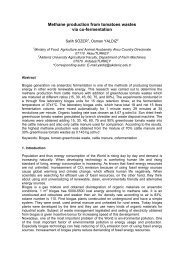
Abstract<br />
The <strong>dielectric</strong> <strong>soil</strong> property can be used as a parameter to measure the <strong>soil</strong> <strong>moisture</strong> content,<br />
because the <strong>dielectric</strong> constant <strong>of</strong> water is much larger than the <strong>dielectric</strong> constant <strong>of</strong> the<br />
other <strong>soil</strong> components. Soil <strong>moisture</strong> <strong>sensor</strong> can be used to automate the traditional irrigation<br />
systems based on real-time <strong>moisture</strong> content measurement. This paper reports on the<br />
<strong>development</strong> <strong>of</strong> a <strong>dielectric</strong> sensing <strong>model</strong> based on the capacitive method. This <strong>model</strong> will<br />
support a future hardware <strong>development</strong> and will be used <strong>for</strong> results comparison.<br />
Key words: Capacitive <strong>sensor</strong>; Automation; Soil <strong>moisture</strong>; Irrigation; OpenModelica.<br />
1. Introduction<br />
Dielectric properties <strong>of</strong> materials are finding increasing applications in agriculture<br />
(Nelson and Trabelsi, 2008). These applications have included the sensing <strong>of</strong> <strong>moisture</strong><br />
content in grain, legume, fruit and meat; radio-frequency and microwave <strong>dielectric</strong> heating <strong>for</strong><br />
pest control, product conditioning and seed treatment; and the sensing <strong>of</strong> <strong>soil</strong> <strong>moisture</strong><br />
content.<br />
The irrigation management based on the monitoring <strong>of</strong> the <strong>soil</strong> <strong>moisture</strong> content<br />
allows <strong>for</strong> the minimization <strong>of</strong> the amount <strong>of</strong> water applied, making its use more efficient.<br />
The relative <strong>dielectric</strong> constant <strong>of</strong> water is about 80 at 20°C. On the other hand, the<br />
<strong>dielectric</strong> constant <strong>of</strong> the others <strong>soil</strong> components are not larger than 10 (Silva, 2005).<br />
There<strong>for</strong>e, the <strong>soil</strong> <strong>moisture</strong> content can be predicted from the <strong>dielectric</strong> constant <strong>of</strong> the <strong>soil</strong>.<br />
The capacitive method can be used to measure the <strong>dielectric</strong> constant <strong>of</strong> <strong>soil</strong>, where<br />
the <strong>soil</strong> is the <strong>dielectric</strong> material localized between the plates <strong>of</strong> the <strong>sensor</strong>.<br />
In an ideal capacitor the <strong>dielectric</strong> material located between its plates is an insulator.<br />
However, there is no perfect insulator. Although it has high resistance to the flow <strong>of</strong> charge,<br />
its value is finite.<br />
So, in a real capacitor, there is a very small current that flows through your <strong>dielectric</strong><br />
material. Thus, its equivalent circuit can be <strong>model</strong>ed as an ideal capacitor in parallel with a<br />
resistor (Salmazo et al., 2006).<br />
The aim <strong>of</strong> this paper is to develop and study a capacitive sensing <strong>model</strong> which can<br />
be used to measure the <strong>dielectric</strong> constant <strong>of</strong> <strong>soil</strong> to determine its water content. Two<br />
situations were considered and compared: (i) the <strong>model</strong> includes the electrical conductivity <strong>of</strong><br />
<strong>soil</strong>; (ii) the <strong>model</strong> doesn’t include the electrical conductivity <strong>soil</strong>.
2. Materials and methods<br />
To predict the relative <strong>dielectric</strong> constant and the electrical conductivity, it is needed<br />
to measure the current flow through the <strong>sensor</strong>, the phase angle between the current and<br />
voltage, and the voltage at the <strong>sensor</strong> output. There<strong>for</strong>e, to measure the current in the circuit,<br />
it was needed to insert a known resistor, R<br />
2<br />
, in series with the <strong>sensor</strong> (Figure 1).<br />
Figure 1 – Circuit designed to predict the complex permittivity.<br />
The admittance, G, and the susceptance, B, <strong>of</strong> the <strong>sensor</strong> can be determined<br />
mathematically, from the voltages (V 1 and V 2 ) and the difference phase between them,<br />
allowing predicting the relative <strong>dielectric</strong> constant. The vector’s diagram <strong>for</strong> the circuit<br />
designed to predict the complex permittivity (Figure 1) is presented in Figure 2.<br />
Figure 2 – Vector’s diagram <strong>for</strong> the circuit designed to predict the complex permittivity.<br />
The capacitive part <strong>of</strong> the <strong>sensor</strong> causes a phase difference between the source<br />
voltage and the total current flow (Figure 3). The phase <strong>of</strong> the voltage at the resistor R<br />
2<br />
is<br />
the same as the current flow.<br />
Figure 3 – Phase difference between the source voltage (in black) and the voltage at the<br />
resistor R<br />
2<br />
(in red).
The impedance <strong>of</strong> the resistive part <strong>of</strong> the <strong>sensor</strong> is much smaller than the impedance<br />
<strong>of</strong> the capacitive part <strong>for</strong> low frequencies. This decreases the sensibility not only <strong>of</strong> the phase<br />
difference change between voltage and current but also <strong>of</strong> the changes in voltage at the<br />
<strong>sensor</strong>’s output. Furthermore, hardware <strong>for</strong> high frequency is <strong>of</strong>ten more expensive and its<br />
project is more complex. Thus, an alternative solution is adding an insulator to the plates <strong>of</strong><br />
the <strong>sensor</strong>.<br />
It was considered, just <strong>for</strong> simulation, that the resistance <strong>of</strong> the insulator is equal to<br />
500 k . But it will depend on the material and its thickness.<br />
OpenModelica was chosen to simulate this circuit because it is a free Object-Oriented<br />
language. Besides, it is a fast-growing area <strong>of</strong> <strong>model</strong>ing and simulation that provides a<br />
structured, computer-supported way <strong>of</strong> doing mathematical and equation-based <strong>model</strong>ing.<br />
Nowadays, Modelica is the most promising <strong>model</strong>ing and simulation language in that it<br />
effectively unifies and generalizes previous object oriented <strong>model</strong>ing languages and provides<br />
a sound basis <strong>for</strong> the basic concepts (Fritzson, 2006).<br />
In the present work there were assembled four <strong>model</strong> types: (i) Soil Model; (ii) A<br />
Resistive Model <strong>for</strong> the resistive part <strong>of</strong> the <strong>sensor</strong>; (iii) A Capacitive Model <strong>for</strong> the capacitive<br />
part <strong>of</strong> the <strong>sensor</strong>; and (iv) A Circuit Model.<br />
For the Soil Model, it was used the relationships not only between <strong>soil</strong> <strong>moisture</strong><br />
content and <strong>soil</strong> conductivity but also between <strong>soil</strong> <strong>moisture</strong> content and relative <strong>dielectric</strong><br />
constant <strong>of</strong> the <strong>soil</strong> found by Santos (2008) <strong>for</strong> a specific type <strong>of</strong> <strong>soil</strong>, as described by<br />
Equations 1 and 2.<br />
26.36 0.101<br />
(1)<br />
( ) 5.01 2<br />
21.32 5.717 (2)<br />
r<br />
where:<br />
-<br />
1<br />
Soil’s conductivity, Sm .<br />
3 3<br />
- Soil’s water content, m m .<br />
- Relative material <strong>dielectric</strong> constant.<br />
r<br />
It was considered that the <strong>sensor</strong> is a parallel plates’ capacitor with <strong>soil</strong> as the<br />
<strong>dielectric</strong> material between its plates. The distance between its plates was considered equal<br />
2<br />
to 0.002 m , and its area equal to 0.010 m .<br />
Only <strong>for</strong> simulation purpose, the <strong>soil</strong> <strong>moisture</strong> content was supposed to vary with time<br />
3 3<br />
3 3<br />
according to the Equation 3, from 0.06 m m to 0.40 m m .<br />
0.34t 0.06 (3)<br />
For the Resistive Model, it was considered that the resistive part <strong>of</strong> the <strong>sensor</strong> varies<br />
according to the conductivity <strong>of</strong> the <strong>soil</strong>.<br />
For the Capacitive Model, it was considered that the capacitive part <strong>of</strong> the <strong>sensor</strong><br />
varies according to the relative <strong>dielectric</strong> constant <strong>of</strong> the <strong>soil</strong>.<br />
The Circuit Model is the same as that in the Figure 1. Furthermore, <strong>for</strong> this <strong>model</strong>, it<br />
was implemented algorithms to determine the root mean square (RMS) values <strong>of</strong> the<br />
voltages, and determine the phase angle between them. Thus, the relative <strong>dielectric</strong> constant<br />
<strong>of</strong> the <strong>soil</strong> was predicted from these values.<br />
The RMS value <strong>of</strong> the sinusoidal signal is defined by Equation 4.<br />
Vp<br />
Vrms<br />
(4)<br />
2<br />
where:<br />
V - Root mean square <strong>of</strong> the sinusoidal voltage signal, V .<br />
rms<br />
V - Peak value <strong>of</strong> the sinusoidal signal, V .<br />
p
The peak value was calculated by the first derivative <strong>of</strong> the signal. When it is around<br />
zero, the signal is around the peak value. Thus, this maximum value was divided by the<br />
square root <strong>of</strong> two. When the algorithm records the peak value, it is also recorded the value<br />
<strong>of</strong> time. Thus, the phase <strong>of</strong> the signal is calculated from the difference <strong>of</strong> two consecutive<br />
peak times. Other <strong>model</strong>s were used from Modelica’s Library, such as Source, Resistor and<br />
Ground Model.<br />
The frequency and the amplitude <strong>of</strong> the voltage source used in simulations were<br />
1 kHz and 10 V , respectively.<br />
A comparison was made between the <strong>dielectric</strong> constant predicted by this <strong>model</strong> and<br />
the <strong>dielectric</strong> constant estimated by a <strong>model</strong> that does not consider the electrical conductivity<br />
<strong>of</strong> the <strong>soil</strong>. This means that the resistor in parallel with the capacitor in the <strong>sensor</strong> <strong>model</strong> was<br />
not considered in this case.<br />
3. Results and discussion<br />
The results are presented in the following figures and discussed further.<br />
In the Figure 4 it is represented the changes in the root mean square voltage at the<br />
<strong>sensor</strong> output over time. It can be observed that when the <strong>soil</strong> water increases the voltage at<br />
the <strong>sensor</strong> output decreases, because the impedance <strong>of</strong> the <strong>sensor</strong> also decreases.<br />
Figure 4 – Changes in root mean square voltage at the <strong>sensor</strong> output.<br />
In the Figure 5 it is shown the phase angle variation <strong>of</strong> the voltage at the resistor<br />
(which has the same phase as the total current) and <strong>of</strong> the voltage at the <strong>sensor</strong>.<br />
Figure 5 – Phase <strong>of</strong> the voltage at the resistor R<br />
2<br />
(in red) and the phase <strong>of</strong> the voltage at the<br />
<strong>sensor</strong> (in black).<br />
The predicted variation <strong>of</strong> the relative <strong>dielectric</strong> constant <strong>of</strong> the <strong>soil</strong> is represented in<br />
the Figure 6. It should be observed that the relationship between the predicted <strong>dielectric</strong><br />
constant <strong>of</strong> the <strong>soil</strong> and time is not linear (Equation 2), although it apparently seems to be.
Figure 6 - Predicted variation <strong>of</strong> the relative <strong>dielectric</strong> constant <strong>of</strong> the <strong>soil</strong>.<br />
The correlation between the relative <strong>dielectric</strong> constant <strong>of</strong> <strong>soil</strong> <strong>model</strong> and the<br />
predicted relative <strong>dielectric</strong> constant <strong>of</strong> the <strong>soil</strong> is shown in the Figure 7. It was obtained an<br />
almost perfect correlation between them, with an uncertainty equals 0.356 , considering<br />
95% <strong>of</strong> probability <strong>of</strong> occurrence <strong>of</strong> random error, that is, two standard deviations <strong>for</strong> more or<br />
<strong>for</strong> less in relation to the estimated value <strong>of</strong> the <strong>dielectric</strong> constant <strong>of</strong> the <strong>soil</strong>.<br />
Figure 7 – Correlation between measured and predicted <strong>dielectric</strong> constants.<br />
The correlation between the relative <strong>dielectric</strong> constant <strong>of</strong> <strong>soil</strong> <strong>model</strong> and the<br />
predicted relative <strong>dielectric</strong> constant <strong>of</strong> the <strong>soil</strong>, neglecting the electrical conductivity effect <strong>of</strong><br />
the <strong>soil</strong>, is shown in the Figure 8. It was obtained a very good correlation between them, with<br />
an uncertainty equals 0.537 , also considering 95% <strong>of</strong> probability<br />
Figure 8 – Correlation between measured and predicted <strong>dielectric</strong> constants neglecting the<br />
electrical conductivity effect <strong>of</strong> the <strong>soil</strong>.
The circuit <strong>for</strong> measuring the <strong>dielectric</strong> constant <strong>of</strong> <strong>soil</strong> is simpler and cheaper than<br />
the circuit which measures the electrical conductivity and <strong>dielectric</strong> constant <strong>of</strong> <strong>soil</strong>. In<br />
addition, the electrical conductivity is an important parameter <strong>for</strong> the crop, because it has<br />
high correlation with <strong>soil</strong> salinity.<br />
4. Conclusions<br />
The following conclusions were drawn based on the results <strong>of</strong> this work:<br />
The <strong>model</strong>s allow a better understanding about capacitive <strong>sensor</strong>s.<br />
The OpenModelica has proven to be a powerful tool to simulate physical <strong>model</strong>s.<br />
The <strong>dielectric</strong> constant <strong>of</strong> the <strong>soil</strong> can be predicted from the proposed circuit.<br />
Neglecting the electrical conductivity <strong>of</strong> the <strong>soil</strong> increases the uncertainties in measurements.<br />
References<br />
BENNING, R.; BIRRELL, S.; GEIGER, D. 2004. Development <strong>of</strong> a Multi-Frequency Dielectric<br />
Sensing System <strong>for</strong> Real-Time Forage Moisture Measurement. ASAE/CSAE Meeting Paper<br />
No. 041100. St. Joseph, Mich.: ASAE.<br />
FRITZSON. 2006. Tutorial: Introduction to Object-Oriented Modeling and Simulation with<br />
OpenModelica. Available from: . Access on 15 May 2010.<br />
NELSON, S. O.; TRABELSI, S. 2008. Dielectric Spectroscopy Measurements on Fruit, Meat,<br />
and Grain. ASABE, v. 51, p. 1829-1834.<br />
RÊGO SEGUNDO, A. K. 2010. Desenvolvimento de <strong>sensor</strong> de teor de água do solo e de<br />
sistema de controle e automação em malha fechada para uso em irrigação. 65f. Dissertation<br />
(MS on Agricultural Engineering). Departamento de Engenharia Agrícola, Universidade<br />
Federal de Viçosa, Viçosa, MG, Brasil.<br />
SILVA, I. O. 2005. Desenvolvimento de um <strong>sensor</strong> capacitivo para o monitoramento de<br />
umidade do solo. 86 f. Dissertation (MS on Irrigation and Drainage), Departamento de<br />
Engenharia Agrícola, Universidade Federal do Ceará, Fortaleza, CE, Brasil.<br />
SALMAZO, L. O.; ALVES, W.; NOBRE, M. A. L. 2006. Materiais Dielétricos – Correlação:<br />
Propriedades e Defeitos. Apostila. Universidade Federal Paulista, Departamento de Física,<br />
Química e Biologia, Presidente Prudente. Available from: .<br />
Access on 22 January 2010.<br />
SANTOS, M. R. 2008. Uso da reflectometria no domínio do tempo para avaliar a distribuição<br />
de nitrato e fós<strong>for</strong>o em colunas de solos fertirrigados. 59 f. Dissertation (MS on Agricultural<br />
Engineering). Departamento de Engenharia Agrícola, Universidade Federal de Viçosa,<br />
Viçosa, MG, Brasil.<br />
Acknowledgements<br />
The authors would like to thank the Foundation <strong>for</strong> Support to Research <strong>of</strong> the State<br />
<strong>of</strong> Minas Gerais - FAPEMIG, Brazil; the National Council <strong>of</strong> Scientific and Technological<br />
Development – CNPq, Brazil; Coordination <strong>of</strong> Improvement <strong>of</strong> Higher Education Personnel –<br />
CAPES, Brazil; the Federal University Federal <strong>of</strong> Ouro Preto, Brasil; and the Gorceix<br />
Fundation, Brazil, <strong>for</strong> their financial support, and the Federal University <strong>of</strong> Viçosa, Brazil, <strong>for</strong><br />
the great opportunity.