1 2 - Classic Ford
1 2 - Classic Ford
1 2 - Classic Ford

Create successful ePaper yourself
Turn your PDF publications into a flip-book with our unique Google optimized e-Paper software.
CFTech<br />
Part<br />
two of<br />
two<br />
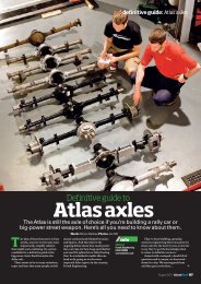
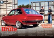
how to: spaceframe the front<br />
1 2<br />
We’ve shown you how to construct the main hoops<br />
that support the strut tops. From there we need to<br />
continue with the fabrication of the strut towers<br />
then mount the body panels to complete the job.<br />
How you make your strut towers is really down to<br />
you but here’s the template that Gary has used to<br />
produce a strong yet lightweight item. Look at an<br />
original item to get an idea of size and shape.<br />
3 4<br />
How to<br />
Spaceframe<br />
the front end<br />
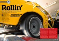
If your classic <strong>Ford</strong>’s rotten to the core ahead<br />
of the bulkhead, why not spaceframe it Here’s<br />
the concluding part of our series.<br />
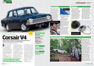
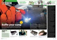
Gary uses a local engineers to stamp out his strut<br />
towers in 2 mm steel. If you’re doing this at home<br />
you’ll need to trace the outline onto the 2 mm plate<br />
then drill and cut out with a jigsaw or similar.<br />
75 6<br />
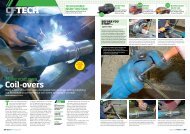
The 2 mm plate will not be strong enough on its<br />
own so stiffening ribs are added to the edges. Gary<br />
uses some 12 mm steel tube which is bent to<br />
shape using a couple of pulleys clamped in a vice.<br />
Words and Photos Jon Betts<br />
Last issue we took you through<br />
the process of fabricating the<br />
main suspension support hoops<br />
and installing the strut tops with the<br />
aid of your homemade jig. In the<br />
second part we will be completing the<br />
process by building the strut support<br />
towers and hanging the body panels<br />
back onto the car.<br />
Due to the cost of good quality<br />
replacement steel wings and steel<br />
bubble arches, the owner of this car has<br />
opted for fibreglass wings with integral<br />
bubble arches. Once again Gary at<br />
Retro Motorsport has come up with a<br />
unique way of mounting these along<br />
with the steel front panel and fibreglass<br />
bonnet. Regardless of what material<br />
your panels are made of, you can either<br />
take Gary’s route or you can always<br />
come up with your own.<br />
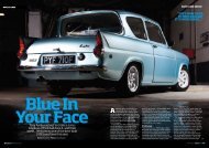
By retaining the original location of<br />
the strut tops and using the standard<br />
Escort crossmember and anti-roll bar<br />
set-up, all the original geometry will be<br />
retained. This means your car will still<br />
handle how it should do once it is<br />
finished and back on the road.<br />
Racing Pedigree<br />
Due to Gary’s race car building<br />
experience he has made a number of<br />
adjustments to this particular set-up,<br />
such as the fully adjustable strut tops.<br />
He is also well aware of the need to<br />
keep the weight down to a minimum,<br />
even on a road car. So wherever<br />
possible, items are given more than<br />
one purpose, for example the front<br />
panel fixing points. These also double<br />
up as the towing eye attachment.<br />
The same goes for the wing fixing<br />
points on the scuttle as these double as<br />
the mounting points for the bonnet<br />
pins. This attention to detail is what<br />
makes Gary’s creations so special,<br />
Info<br />
Cost:<br />
Typical spaceframe<br />
conversion costs from<br />
£1400 including<br />
bulkhead and camber<br />
adjustable top plates<br />
Tools Required :<br />
Grinder, MIG welder,<br />
spot welder, drill,<br />
hole cutter, hole<br />
flaring tool, hacksaw,<br />
tin snips, pipe<br />
bender, plumb line,<br />
tape measure.<br />
Time taken:<br />
Couple of days to<br />
a week<br />
Contact:<br />
Retro Motorsport<br />
01279 452799<br />
therefore by following his lead you can<br />
turn your project into something<br />
special as well.<br />
Know Your Limits<br />
One thing to remember when taking<br />
on something as integral as structural<br />
work. There is obviously a considerable<br />
amount of fabrication and welding<br />
required on a job like this and it is not<br />
for the faint hearted or those whose<br />
skills fall short of their enthusiasm.<br />
Remember your life and that of many<br />
other innocent bystanders may rely on<br />
it, so know your own limitations and if<br />
necessary seek the help of a<br />
professional such as Gary before<br />
commencing any work yourself.<br />
Special thanks to Gary for again<br />
allowing us into his workshop and<br />
sharing some of his closely guarded<br />
secrets, and Ben Szanto who is the<br />
lucky owner of this Mk1 Escort.<br />
Before you<br />
start...<br />
Safety FIRST<br />
Always remember safety first when it<br />
comes to using power tools and welders,<br />
so that means goggles and gloves where<br />
necessary, and a decent welding mask —<br />
and don’t use a cheap hand-held one.<br />
With power tools, remember to always<br />
use the correct guards and clamp the<br />
work piece securely.<br />
contact<br />
Retro Motorsport<br />
01279 452799<br />
retromotorsport@excite.com<br />
www.retromotorsport.co.uk<br />
The tube is used down the back of the tower as you<br />
can see here. It doesn’t go all the way to the bottom<br />
as the chassis leg gets in the way — test fit it on the<br />
car before cutting to size.<br />
7<br />
Clamp the pieces together and tack weld in<br />
position. The tower itself is clamped to the<br />
workbench and then the small strip is manoeuvred<br />
into position and then tacked every few inches.<br />
On the other side of the tower Gary uses a 10 mm<br />
strip of 2 mm steel. This is marked and then cut out<br />
before being bent to shape to follow the contours<br />
of the tower.<br />
8<br />
The same is done to the tube and then everything<br />
is fully seam welded together. This needs to be<br />
repeated on all four strut tower pieces before they<br />
can be fitted to the car.<br />
130 June 2010<br />
June 2010 131
how to: spaceframe the front<br />
9<br />
10 11<br />
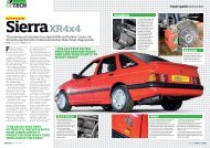
Here you can see a standard strut tower compared<br />
to the shape and design of Gary’s strut tower. They<br />
are both very similar but I know which one I would<br />
rather have on my car!<br />
12<br />
Once all four are completed you can then begin<br />
fitting them to the car. Tack the top in position onto<br />
the tube and strut top. You will need to flatten the<br />
tub slightly so it all fits together properly.<br />
13<br />
Next tack the bottom in position using the marks<br />
you made earlier from the original strut towers. The<br />
towers should sit at right angles to the chassis rail.<br />
Only tack at this time until all four are in place.<br />
14<br />
Gary has his own positioning for his strut towers<br />
which differs slightly from the original position but<br />
it’s best if you stick with the factory figures to retain<br />
the standard geometry.<br />
15<br />
Once all four are in position and fully welded you<br />
can then box the front of the towers off to tie<br />
everything together. Gary used some slotted 2 mm<br />
plate and also added a custom made strut brace.<br />
16<br />
This particular car is getting fibreglass wings with<br />
the bubble arches already added so these were<br />
lined up with the swage lines on the door and then<br />
fixed to the A post with a couple of rivnuts.<br />
17<br />
It will take some time to get it all looking right and<br />
you’ll also need the help of an assistant to hold the<br />
panels as you line them up. Take your time because<br />
if you get this wrong the car just won’t look right.<br />
The front panel is positioned with some flat bar<br />
bolted where the front bumper irons fit and then<br />
clamped to the wings. A little bit of trimming and<br />
bending is required here to get everything right.<br />
Using an M8 bolt and some thick washer spaced<br />
out with some 10 mm outside diameter tube, Gary<br />
mocks up the first of the supports for the front end.<br />
18 19 20<br />
A similar length of tube is bolted to the wing lip and<br />
then another length of 10 mm tube is fitted<br />
between the two. You will need to profile the ends<br />
and then tack into place.<br />
A further mounting tube is then attached to the<br />
lower part of the main hoop and forms a<br />
triangulation between the three fixing points. Once<br />
fitted all three can be fully welded into position.<br />
This process will need to be repeated on the other<br />
side and then a similar piece of bar is bent to the<br />
same shape as the edge of the front panel and<br />
fitted between the two fixings on the wings.<br />
June 2010 133
CFTech<br />
21<br />
22 23<br />
Here you can see how all the tubes converge at the<br />
same piece of tube which is then bolted to the<br />
edge of the wing. This makes the whole assembly<br />
extremely strong.<br />
24<br />
A strip of metal (1.2 mm) cut slightly larger than<br />
required is then bent to the contour of the slam<br />
panel. Lay it in position and then draw around it.<br />
Also make sure that the bonnet clears everything.<br />
25<br />
Before cutting the piece to shape, Gary adds some<br />
detail by filling it with lots of holes and then<br />
swaging them with a hole flare tool. This not only<br />
lightens the panel but also adds strength.<br />
26<br />
Once all the holes are done, the panel is clamped<br />
back on the car so that you can mark round it again.<br />
It can then be removed for final trimming with<br />
some tin snips and then re-clamped to the car.<br />
Gary uses a spot welder to attach the front edge of<br />
the front panel to the new slam panel. If you don’t<br />
have access to a spot welder, drill a series of holes<br />
in the new slam panel and plug weld it in place.<br />
Along the back edge its out with the Mig welder<br />
again. No need to weld all the way along, just mark<br />
off every inch and then weld an inch and skip an<br />
inch all the way along the panel.<br />
27 28 29<br />
With the front secure, next fix the wings at the top<br />
edge. Gary designed a small bracket to be welded<br />
to the top of the scuttle area, fixing the wing in<br />
place and acting as the mount for the bonnet pin.<br />
Having made a suitable cardboard template, this is<br />
then transferred to some 1.2 mm steel and then cut<br />
and bent to shape. A hole is drilled for the bonnet<br />
pin and for a captive nut to secure the wing in place.<br />
The completed bracket is welded to the car and<br />
replicated on the other side. This almost completes<br />
the fixing of the front panel work with just the lower<br />
edge of the front panel to fix in position.<br />
30 31 32<br />
Next<br />
Month<br />
fitting a<br />
weld-in cage<br />
This is done with a towing eye (most modern cars<br />
have this type so you’ll find one at your scrapyard)<br />
and a length of tube with a thick washer welded<br />
onto one end as well as the towing eye itself.<br />
The front panel is then drilled to accept the metal<br />
tube using a suitable hole saw inline with the<br />
anti-roll bar bracket. Once the hole is drilled, the<br />
tube is cut to length and welded to the front panel.<br />
Drill a hole in the anti-roll bar bracket and weld a nut<br />
that fits the towing eye’s thread at the back. Insert<br />
the eye into the tube and tighten up to secure the<br />
front panel. Then strip it all down ready for paint!<br />
134 June 2010