OPTIFLEX 1300 C
OPTIFLEX 1300 C
OPTIFLEX 1300 C

Create successful ePaper yourself
Turn your PDF publications into a flip-book with our unique Google optimized e-Paper software.
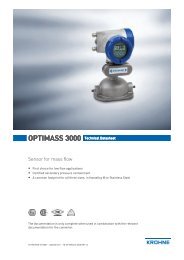
<strong>OPTIFLEX</strong> <strong>1300</strong> C Technical Datasheet<br />
Guided Radar (TDR) Level Meter<br />
• Universal device that can measure level of liquids, pastes, granulates, powders,<br />
and liquid interface<br />
• Easy to install: onsite calibration is not needed<br />
• Operates up to 300 bar / 4350 psi<br />
© KROHNE 09/2010 - 4000112206 - TD <strong>OPTIFLEX</strong> <strong>1300</strong> R11 en
CONTENTS<br />
<strong>OPTIFLEX</strong> <strong>1300</strong> C<br />
1 Product features 4<br />
1.1 The superior TDR solution ............................................................................................... 4<br />
1.2 Applications ...................................................................................................................... 6<br />
1.3 Measuring principle.......................................................................................................... 8<br />
2 Technical data 11<br />
2.1 Technical data................................................................................................................. 11<br />
2.2 Application table for probe selection ............................................................................. 17<br />
2.3 Pressure/temperature table for probe selection .......................................................... 18<br />
2.4 Measurement limits ....................................................................................................... 19<br />
2.5 Dimensions and weights ................................................................................................ 22<br />
3 Installation 36<br />
3.1 Intended use ................................................................................................................... 36<br />
3.2 Pre-installation requirements ....................................................................................... 36<br />
3.3 How to prepare the tank before you install the device.................................................. 36<br />
3.3.1 General information for nozzles........................................................................................... 36<br />
3.3.2 Installation requirements for concrete roofs....................................................................... 38<br />
3.4 Installation recommendations for liquids...................................................................... 39<br />
3.4.1 General requirements .......................................................................................................... 39<br />
3.4.2 Standpipes............................................................................................................................. 40<br />
3.5 Installation recommendations for solids....................................................................... 44<br />
3.5.1 Nozzles on conical silos........................................................................................................ 44<br />
3.5.2 Traction loads on the probe.................................................................................................. 46<br />
3.6 How to install the device on the tank ............................................................................. 47<br />
3.6.1 How to install a device with a flange connection ................................................................. 47<br />
3.6.2 How to install a device with a threaded connection............................................................. 47<br />
3.6.3 Installation recommendations for non-metallic tanks and pits .......................................... 48<br />
3.6.4 How to assemble the remote housing.................................................................................. 49<br />
4 Electrical connections 50<br />
4.1 Safety instructions.......................................................................................................... 50<br />
4.2 Electrical installation: outputs 1 and 2 .......................................................................... 50<br />
4.2.1 Non-Ex................................................................................................................................... 51<br />
4.2.2 Ex i ......................................................................................................................................... 51<br />
4.2.3 Ex d........................................................................................................................................ 51<br />
4.2.4 PROFIBUS PA........................................................................................................................ 51<br />
4.2.5 FOUNDATION Fieldbus ......................................................................................................... 51<br />
4.3 Protection category ........................................................................................................52<br />
4.4 Networks ........................................................................................................................ 53<br />
4.4.1 General information.............................................................................................................. 53<br />
4.4.2 Point-to-point networks ....................................................................................................... 53<br />
4.4.3 Multi-drop networks ............................................................................................................. 54<br />
4.4.4 Fieldbus networks................................................................................................................. 55<br />
2 www.krohne.com 09/2010 - 4000112206 - TD <strong>OPTIFLEX</strong> <strong>1300</strong> R11 en
<strong>OPTIFLEX</strong> <strong>1300</strong> C<br />
CONTENTS<br />
5 Order form 57<br />
5.1 Device data ..................................................................................................................... 57<br />
5.2 Rating data...................................................................................................................... 58<br />
5.3 Contact data.................................................................................................................... 58<br />
6 Notes 59<br />
09/2010 - 4000112206 - TD <strong>OPTIFLEX</strong> <strong>1300</strong> R11 en<br />
www.krohne.com<br />
3
1 PRODUCT FEATURES<br />
<strong>OPTIFLEX</strong> <strong>1300</strong> C<br />
1.1 The superior TDR solution<br />
This device is a Guided Radar (TDR) Level Meter for measuring distance, level, interface, level<br />
and interface, volume and mass. It has higher signal dynamics and a sharper pulse than<br />
conventional TDR devices and therefore better reproducibility and accuracy. A variant with a<br />
remote converter can be mounted up to 14.5 m / 47.6 ft from the probe. The device can operate<br />
at very low and very high process temperatures as long as the process connection temperature<br />
limits are observed.<br />
1 Touch screen with 4-button operation<br />
2 2-wire level meter<br />
3 Converter is rotatable and removable under process conditions<br />
4 5 different types of probes suitable for a wide range of media<br />
5 Optional ESD protection (30 kV) or Metaglas® dual process sealing system for dangerous products<br />
6 Same converter for Ex and non-Ex<br />
7 Large graphical display<br />
4<br />
www.krohne.com<br />
09/2010 - 4000112206 - TD <strong>OPTIFLEX</strong> <strong>1300</strong> R11 en
<strong>OPTIFLEX</strong> <strong>1300</strong> C<br />
PRODUCT FEATURES 1<br />
Highlights<br />
• Displays level and interface<br />
• PACTware and DTMs included as standard<br />
• Optional FOUNDATION Fieldbus and PROFIBUS PA outputs<br />
• Optional second current output - used for displaying interface measurements, for example<br />
• High-pressure and high-temperature versions<br />
• Optimal process safety (with Metaglas® dual process sealing system for dangerous products)<br />
• Display in 9 languages: even in Chinese, Japanese and Russian<br />
• Available in stainless steel and Hastelloy® C-22. Other materials are available on request:<br />
monel, tantalum, titanium, duplex, ...<br />
• Angled single cable and rod probes are available on request for installation in tanks which<br />
contain obstructions<br />
Industries<br />
• Chemicals & Petrochemicals<br />
• Oil & Gas<br />
• Minerals & Mining<br />
• Wastewater<br />
• Pulp & Paper<br />
• Food & Beverages<br />
• Pharmaceutical<br />
• Energy<br />
Applications<br />
• Blending tanks<br />
• Distillation tanks<br />
• Process tanks<br />
• Separator<br />
• Solid silos (inventory)<br />
• Storage tanks<br />
09/2010 - 4000112206 - TD <strong>OPTIFLEX</strong> <strong>1300</strong> R11 en<br />
www.krohne.com<br />
5
1 PRODUCT FEATURES<br />
<strong>OPTIFLEX</strong> <strong>1300</strong> C<br />
1.2 Applications<br />
1. Level measurement of liquids<br />
The level meter can measure the level of a wide<br />
range of liquid products on a large variety of<br />
installations within the stated pressure and<br />
temperature range, including LPG and LNG. It does<br />
not require calibration or commissioning when<br />
installed. A Metaglas® option is also available for<br />
dangerous products and ensures that no leakage is<br />
possible.<br />
A number of probe end attachments are available.<br />
For example, the user can fix the end of cable probes<br />
to heating coils: the heat prevents deposits building<br />
up on the probe.<br />
2. Interface measurement of liquids<br />
The level meter can measure interface with or<br />
without an air gap. It can also measure level and<br />
interface simultaneously. It has an optional second<br />
analogue output.<br />
The coaxial probe of the level meter has a top dead<br />
zone of only 10 mm / 0.4¨: this makes it ideal for<br />
tracking full tank or ballast interface.<br />
6<br />
www.krohne.com<br />
09/2010 - 4000112206 - TD <strong>OPTIFLEX</strong> <strong>1300</strong> R11 en
<strong>OPTIFLEX</strong> <strong>1300</strong> C<br />
PRODUCT FEATURES 1<br />
3. Level measurement of solids<br />
The level meter has a strengthened Ø8 mm / 0.3¨<br />
single cable probe for measuring powders and<br />
granulates in silos up to 35 m / 115 ft high.<br />
The Ø4 mm / 0.15¨ single cable probe is used for<br />
small silos. An ESD protection (30 kV) option is also<br />
available.<br />
If a product has a very low dielectric constant<br />
(ε r
1 PRODUCT FEATURES<br />
<strong>OPTIFLEX</strong> <strong>1300</strong> C<br />
5. Measurement of liquids in a still well<br />
You can also install the level meter in a still well if<br />
there are vortices, agitators or other obstructions in<br />
the tank. It is also suitable for tanks with floating<br />
roofs. The level meter's setup wizard allows you to<br />
quickly configure your device to suit specific types of<br />
installations and get the best possible performance<br />
from it.<br />
6. Remote display on high or inaccessible tanks<br />
If it is difficult or impossible to read the level meter's<br />
integrated display at the top of the tank, we<br />
recommend the remote display variant. It is<br />
provided with a cable up to 14.5 m / 47.6 ft long and a<br />
bracket for mounting in an accessible position.<br />
If there is vibration in the installation, we also<br />
recommend that you attach the remote converter to<br />
a wall or another safe object that is not attached to<br />
the installation.<br />
1.3 Measuring principle<br />
This Guided Radar (TDR) level meter has been developed from a proven technology called Time<br />
Domain Reflectometry (TDR).<br />
The device transmits low-intensity electromagnetic pulses of approximately half a nanosecond<br />
width along a rigid or flexible conductor. These pulses move at the speed of light. When the<br />
pulses reach the surface of the product to be measured, the pulses are reflected with an<br />
intensity that depends on the dielectric constant, ε r , of the product (for example, water has a high<br />
dielectric constant and reflects the pulse back to the meter converter at 80% of its original<br />
intensity).<br />
The device measures the time from when the pulse is transmitted to when it is received: half of<br />
this time is equivalent to the distance from the reference point of the device (the flange facing) to<br />
the surface of the product. The time value is converted into an output current of 4...20 mA and/or<br />
a digital signal.<br />
8<br />
www.krohne.com<br />
09/2010 - 4000112206 - TD <strong>OPTIFLEX</strong> <strong>1300</strong> R11 en
<strong>OPTIFLEX</strong> <strong>1300</strong> C<br />
PRODUCT FEATURES 1<br />
Dust, foam, vapor, agitated surfaces, boiling surfaces, changes in pressure, changes in<br />
temperature and changes in density do not have an effect on device performance.<br />
The illustration that follows shows a snapshot of what a user would see on an oscilloscope, if the<br />
level of one product is measured.<br />
Level measurement principle (direct measurement)<br />
Figure 1-1: Level measurement principle<br />
1 Time 0: The electromagnetic (EM) pulse is transmitted by the converter<br />
2 Time 1: The pulse goes down the probe at the speed of light in air, V1<br />
3 Time 2: The pulse is reflected<br />
4 Time 3: The pulse goes up the probe at speed, V1<br />
5 Time 4: The converter receives the pulse and records the signal<br />
6 The EM pulse moves at speed, V1<br />
7 Transmitted EM pulse<br />
8 Half of this time is equivalent to the distance from the reference point of the device (the flange facing) to the surface<br />
of the product<br />
9 Received EM pulse<br />
The illustration that follows shows a snapshot of what a user would see on an oscilloscope, if the<br />
level and/or interface of products are measured.<br />
Interface measurement: The dielectric constant of the top liquid must be less than the dielectric<br />
constant of the bottom liquid. If not, or if there is too small a difference, the device may not<br />
measure correctly.<br />
09/2010 - 4000112206 - TD <strong>OPTIFLEX</strong> <strong>1300</strong> R11 en<br />
www.krohne.com<br />
9
1 PRODUCT FEATURES<br />
<strong>OPTIFLEX</strong> <strong>1300</strong> C<br />
Level and interface measurement principle (direct measurement)<br />
Figure 1-2: Level and interface measurement principle (2 liquids in the tank)<br />
1 Time 0: The electromagnetic (EM) pulse is transmitted by the converter<br />
2 Time 1: The pulse goes down the probe at the speed of light in air, V1<br />
3 Time 2: Part of the pulse is reflected at the surface of the top liquid, the remaining pulse goes down the probe<br />
4 Time 3: Part of the pulse goes up the probe at speed, V1. The remaining pulse goes down the probe at the speed of<br />
light in the top product, V2<br />
5 Time 4: The converter receives part of the pulse pulse and records the signal. The remaining pulse is reflected at the<br />
interface of the 2 liquids<br />
6 Time 5: The remaining pulse is goes up the probe at speed, V2<br />
7 Time 6: The remaining pulse goes up the probe at speed, V1<br />
8 Time 7: The converter receives the remaining pulse and records the signal<br />
9 The EM pulse moves at speed, V1<br />
10 The EM pulse moves at speed, V2<br />
11 Transmitted EM pulse<br />
12 Received EM pulse (distance to the top liquid)<br />
13 Received EM pulse (distance to the interface of 2 liquids)<br />
If products have a very low dielectric constant (ε r
<strong>OPTIFLEX</strong> <strong>1300</strong> C<br />
TECHNICAL DATA 2<br />
2.1 Technical data<br />
• The following data is provided for general applications. If you require data that is more<br />
relevant to your specific application, please contact us or your local representative.<br />
• Additional information (certificates, special tools, software,...) and complete product<br />
documentation can be downloaded free of charge from the website (Download Center).<br />
Measuring system<br />
Measuring principle<br />
Application range<br />
Primary measured value<br />
Secondary measured value<br />
Design<br />
Construction<br />
Options<br />
Accessories<br />
Max. measuring range<br />
Dead zone<br />
Display and User interface<br />
Display<br />
Interface languages<br />
2-wire loop-powered level transmitter; Time Domain Reflectometry (TDR)<br />
Level measurement of liquids, pastes, slurries, powders and granulates<br />
Time between the emitted and received signal<br />
Distance, level, volume, mass and/or interface<br />
The measurement system consists of a measuring sensor (probe) and a signal<br />
converter which is available in a compact or remote version<br />
Integrated LCD display with sun cover (-20…+60°C /-4…+140°F);<br />
if the ambient temperature is not in these limits, the display switches off<br />
2nd current output<br />
ESD protection (max. 30 kV)<br />
Metaglas ® (dual process sealing system for dangerous products (ammonia,<br />
chlorine, ...)) 1<br />
Remote housing connected to the probe via a flexible conduit<br />
Standard lengths: 2 m / 6.6 ft, 4.5 m / 14.8 ft, 9.5 m / 31.2 ft and 14.5 m / 47.6 ft<br />
Probe end types (not for rod and coaxial probes)<br />
Standard: Counterweights (refer to counterweight dimensions in "Technical data:<br />
Dimensions and weights".)<br />
Options: Turnbuckle, chuck, threaded end, crimped end, open end<br />
Weather protection<br />
Double rod Ø8 mm / 0.3¨: 4 m / 13 ft<br />
Single rod Ø8 mm / 0.3¨: 4 m / 13 ft<br />
Single rod Ø8 mm / 0.3¨ (segmented): 6 m / 20 ft<br />
Coaxial Ø22 mm / 0.9¨: 6 m / 20 ft<br />
Coaxial Ø22 mm / 0.9¨ (segmented): 6 m / 20 ft<br />
Double cable Ø4 mm / 0.15¨: 8 m / 26 ft<br />
Single cable Ø2 mm / 0.08¨: 35 m / 115 ft (for liquids only)<br />
Single cable Ø4 mm / 0.15¨: 35 m / 115 ft (For liquids only. An angled probe is<br />
available on request for installations with very low ceilings or objects in the tank<br />
that prevent installation on top of the tank.)<br />
Single cable Ø8 mm / 0.3¨: 35 m / 115 ft<br />
(For solids only. Tolerance, probe length: -1%/+0%.)<br />
This depends on the type of probe. For more data, refer to Measurement limits on<br />
page 19.<br />
LCD display<br />
9 lines, 160×160 pixels in 8-step grayscale with 4-button keypad<br />
English, German, French, Italian, Spanish, Portuguese, Japanese, Chinese<br />
(Mandarin) and Russian<br />
09/2010 - 4000112206 - TD <strong>OPTIFLEX</strong> <strong>1300</strong> R11 en<br />
www.krohne.com<br />
11
2 TECHNICAL DATA<br />
<strong>OPTIFLEX</strong> <strong>1300</strong> C<br />
Accuracy<br />
Resolution 1mm/ 0.04¨<br />
Repeatability<br />
Accuracy (in direct mode)<br />
Accuracy (in TBF mode)<br />
±1 mm/ ±0.04¨<br />
Liquids:<br />
±3 mm/ ±0.12¨, when distance < 10 m / 33 ft;<br />
±0.03% of measured distance, when distance > 10 m / 33 ft<br />
Powders:<br />
±20 mm / ±0.8¨<br />
Interface:<br />
±10 mm / ±0.4¨ (εr constant)<br />
±20 mm / ±0.8¨ (ε r constant)<br />
Minimum layer (interface) 50 mm / 2¨<br />
Reference conditions acc. to EN 60770<br />
Temperature +20°C ±5°C / +68°F ±10°F<br />
Pressure<br />
1013 mbara ±20 mbar / 14.69 psia ±0.29 psi<br />
Relative air humidity 60% ±15%<br />
Operating conditions<br />
Temperature<br />
Ambient temperature<br />
Storage temperature<br />
Process connection temperature<br />
Thermal shock resistance<br />
Pressure<br />
-40…+80°C /-40…+175°F<br />
(Ex: see supplementary operating instructions or approval certificates)<br />
-40…+85°C /-40…+185°F<br />
Standard<br />
-40…+200°C/-40…+390°F (according to the temperature limits of the gasket<br />
material. Refer to "Material" in this table.)<br />
(Ex: see supplementary operating instructions or approval certificates) 2<br />
High-Temperature (HT) and High-Temperature / High-Pressure (HT/HP) versions<br />
with FKM/FPM and Kalrez ® 6375 gaskets<br />
+300°C / +570°F (single cable Ø2 mm / 0.08¨ probe only)<br />
(Ex: see supplementary operating instructions or approval certificates) 2<br />
HT and HT/HP versions with EPDM gaskets<br />
+250°C / +480°F (single cable Ø2 mm / 0.08¨ probe only)<br />
(Ex: see supplementary operating instructions or approval certificates) 2<br />
100°C/min<br />
Operating pressure Single cable Ø8 mm / 0.3¨ probe<br />
-1…40 barg / -14.5…580 psig<br />
subject to process connection temperature and probe type used 2<br />
High-Pressure (HP) version<br />
max. 300 barg / 4350 psig (single cable Ø2 mm / 0.08¨ probe only)<br />
subject to process connection temperature and probe type used 2<br />
All other probe types<br />
-1…100 barg / -14.5…1450 psig<br />
subject to process connection temperature and probe type used 2<br />
12<br />
www.krohne.com<br />
09/2010 - 4000112206 - TD <strong>OPTIFLEX</strong> <strong>1300</strong> R11 en
<strong>OPTIFLEX</strong> <strong>1300</strong> C<br />
TECHNICAL DATA 2<br />
Other conditions<br />
Dielectric constant (ε r )<br />
Level in direct mode:<br />
≥1.4 for coaxial probe; ≥1.6 for single and double probes<br />
Interface in direct mode:<br />
ε r (interface) >> ε r (level)²<br />
Level in TBF mode:<br />
≥1.1<br />
Vibration resistance<br />
IEC 60068-2-6 and EN 50178 (10...57 Hz: 0.075 mm / 57...150 Hz:1g)<br />
Protection category IP 66/67 equivalent to NEMA 6-6X<br />
Installation conditions<br />
Process connection size<br />
Process connection position<br />
Dimensions and weights<br />
Refer to "Installation: How to prepare the tank before you install the device" and<br />
"Technical data: Measurement limits"<br />
Make sure that there are not any obstructions directly below the process<br />
connection for the device.<br />
Refer to "Technical data: Dimensions and weights"<br />
Material<br />
Housing<br />
Standard: Aluminium<br />
Option: Stainless steel (1.4404 / 316L)<br />
Single rod (single-piece) Standard: Stainless steel (1.4404 / 316L)<br />
Option: Hastelloy ® C-22 (2.4602) 3<br />
On request: Stainless steel (1.4404 / 316L) in a PVC, PVDF or PP protective sheath<br />
On request: Monel; Tantalum; Titanium; Duplex<br />
Single rod (segmented) Standard: Stainless steel (1.4404 / 316L)<br />
Double rod Standard: Stainless steel (1.4404 / 316L)<br />
Option: Hastelloy ® C-22 (2.4602)<br />
On request: Monel; Tantalum; Titanium; Duplex<br />
Coaxial (single-piece) Standard: Stainless steel (1.4404 / 316L)<br />
Option: Hastelloy ® C-22 (2.4602)<br />
Coaxial (segmented) Standard: Stainless steel (1.4404 / 316L)<br />
Single cable Standard: Stainless steel (1.4401 / 316)<br />
Option: Hastelloy ® C-22 (2.4602)<br />
- only for the Ø2 mm / 0.08¨ or Ø4 mm / 0.15¨ single cable probes<br />
On request: FEP-coated stainless steel (-20...+150°C / -4...+300°F)<br />
- only for the Ø4 mm / 0.15¨ single cable probe<br />
Double cable Stainless steel (1.4401 / 316)<br />
Process fitting Standard: Stainless steel (1.4404 / 316 L)<br />
Option: Hastelloy ® C-22 (2.4602)<br />
On request: Monel; Tantalum; Titanium; Duplex<br />
Gaskets<br />
FKM/FPM (-40…+200°C/-40…+390°F); Kalrez ® 6375 (-20…+200°C/-4…+390°F);<br />
EPDM (-50...+150°C / -58...+300°F) - all probes except single cable Ø8 mm / 0.3¨ 4<br />
Weather protection (Option) Stainless steel (1.4301 / 304)<br />
Protective sheath<br />
(On request for single rod only)<br />
Conduit for remote housing<br />
(Option)<br />
PP (-40…+90°C /-40…+194°F); PVC (-15…+80°C / +5…+176°F);<br />
PVDF (-40…+150°C /-40…+300°F)<br />
Zinc-coated steel in a PVC sheath (-40...+105°C / -40...+220°F)<br />
09/2010 - 4000112206 - TD <strong>OPTIFLEX</strong> <strong>1300</strong> R11 en<br />
www.krohne.com<br />
13
2 TECHNICAL DATA<br />
<strong>OPTIFLEX</strong> <strong>1300</strong> C<br />
Process connections<br />
Thread<br />
Single cable Ø2 mm / 0.08¨<br />
Single cable Ø8 mm / 0.3¨<br />
All other probes<br />
G ½; ½ NPT; ½ NPTF (for the HT/HP version)<br />
G1½; 1½ NPT<br />
G ¾…1½; ¾…1½ NPT<br />
Flange versions for single cable Ø8 mm / 0.3¨, , double rod and double cable probes<br />
EN<br />
ASME<br />
JIS<br />
DN40…150 in PN16, PN40, PN63 or PN100; others on request<br />
1½¨…8¨ in 150 lb, 1½¨...6¨ in 300 lb, 1½¨...4¨ in 600 lb or 900 lb; 1½¨...2¨ in 1500 lb;<br />
others on request<br />
40…100A in 10K; others on request<br />
Flange versions for single cable Ø2 mm / 0.08¨ probe<br />
EN<br />
ASME<br />
JIS<br />
Flange versions for all other probes<br />
EN<br />
ASME<br />
JIS<br />
Other options for single and double rod probes<br />
SMS<br />
Tri-clamp<br />
Others<br />
Electrical connections<br />
DN25…150 in PN16, PN40, PN63 or PN100; others on request<br />
1¨…8¨ in 150 lb, 1½¨...6¨ in 300 lb, 1¨...4¨ in 600 lb or 900 lb, 1¨...2¨ in 1500 lb, 1¨ in<br />
2500 lb; others on request<br />
40…100A in 10K; others on request<br />
DN25…150 in PN16, PN40, PN63 or PN100; others on request<br />
1¨…8¨ in 150 lb, 1½¨...6¨ in 300 lb, 1¨...4¨ in 600 lb or 900 lb, 1¨...2¨ in 1500 lb; others<br />
on request<br />
40…100A in 10K; others on request<br />
Available on request<br />
Available on request<br />
Others on request<br />
Power supply Terminals output 1 - Non-Ex / Ex i:<br />
14…30 VDC; min./max. value for an output of 22 mA at the terminal<br />
Terminals output 1 - Ex d:<br />
20…36 VDC; min./max. value for an output of 22 mA at the terminal<br />
Terminals output 2 - Non-Ex / Ex i / Ex d:<br />
10…30 VDC; min/max. value for an output of 22 mA at the terminal (additional<br />
power supply needed - output only)<br />
Cable entry<br />
M20×1.5; ½ NPT<br />
G ½ (not for FM- and CSA-approved devices. Not for stainless steel housings.)<br />
M25×1.5 (for stainless steel housings only)<br />
Cable gland<br />
Standard: none<br />
Options: M20×1.5 (for non-Ex and Ex-approved devices with M20×1.5 and M25×1.5<br />
cable entries); others are available on request<br />
Cable entry capacity (terminal) 0.5…1.5 mm²<br />
Input and output<br />
Current output<br />
Output signal (Output 1) 4…20 mA HART ® or 3.8…20.5 mA acc. to NAMUR NE 43 5<br />
Output signal (Output 2 -<br />
optional)<br />
4…20 mA (no HART ® signal) or 3.8…20.5 mA acc. to NAMUR NE 43 (optional)<br />
14<br />
www.krohne.com<br />
09/2010 - 4000112206 - TD <strong>OPTIFLEX</strong> <strong>1300</strong> R11 en
<strong>OPTIFLEX</strong> <strong>1300</strong> C<br />
TECHNICAL DATA 2<br />
Resolution ±3 µA<br />
Temperature drift<br />
Typically 50 ppm/K<br />
Error signal High: 22 mA; Low: 3.6 mA acc. to NAMUR NE 43<br />
PROFIBUS PA<br />
Type<br />
Function blocks<br />
Protocol / Communication<br />
standard<br />
Physical layer types<br />
Other features<br />
Device power supply (24 V input)<br />
Current consumption on<br />
PROFIBUS network<br />
Output data<br />
4-wire (+ local HART) level transmitter; Time Domain Reflectometry (TDR)<br />
11 (level, distance, interface level, interface distance, layer, interface conversion,<br />
ullage conversion, layer conversion, level conversion, level mass and distance<br />
mass)<br />
PROFIBUS PA protocol that agrees with IEC 61158-2, galvanically isolated<br />
Standard power signaling, bus powered, non I.S.<br />
Bus interface with integrated reverse polarity protection<br />
18...30 VDC<br />
20 mA<br />
Level, distance, interface level, interface distance, layer, interface conversion,<br />
ullage conversion, layer conversion, level conversion, level mass and distance mass<br />
None<br />
Typically 0 mA (FDE =Fault Disconnection Electronic)<br />
Input data<br />
Error current FDE<br />
Address range 0...125. Default address: 126.<br />
FOUNDATION Fieldbus<br />
Type<br />
4-wire (+ local HART) level transmitter; Time Domain Reflectometry (TDR)<br />
Function blocks<br />
1 × Resource Block (RB), 4 × Analog Input Blocks (AI), 1 × Transducer Block (TB)<br />
Analog Input Block: 50 ms<br />
Protocol / Communication Foundation Fieldbus protocol that agrees with IEC 61158-2, galvanically isolated<br />
standard<br />
ITK version 5.1<br />
Physical layer types<br />
Standard power signaling, bus powered, non I.S.<br />
Other features<br />
Bus interface with integrated reverse polarity protection<br />
Device power supply (24 V input) 18...30 VDC<br />
Bus power supply<br />
9...32 VDC (non-Ex); 9...17.5 VDC (intrinsically-safe)<br />
Basic current<br />
20 mA<br />
Maximum error current<br />
20 mA<br />
Start current after 10 ms 20 mA<br />
Polar sensitivity<br />
Yes<br />
Minimum cycle time<br />
100 ms<br />
Output data<br />
Level, distance, level conversion, interface level, interface distance, layer, interface<br />
conversion, ullage conversion, layer conversion, level conversion, level mass or<br />
distance mass<br />
Input data<br />
None<br />
Error current FDE<br />
Typically 0 mA (FDE =Fault Disconnection Electronic)<br />
Link Master function<br />
Not supported<br />
09/2010 - 4000112206 - TD <strong>OPTIFLEX</strong> <strong>1300</strong> R11 en<br />
www.krohne.com<br />
15
2 TECHNICAL DATA<br />
<strong>OPTIFLEX</strong> <strong>1300</strong> C<br />
Approvals and certification<br />
CE<br />
Explosion protection<br />
ATEX (approval for fieldbus<br />
outputs pending)<br />
IECEx (approval for fieldbus<br />
outputs options pending)<br />
FM - Dual Seal-approved<br />
(approval for fieldbus output<br />
options pending)<br />
CSA - Dual Seal-approved<br />
(approval for Drop antenna,<br />
hygienic antenna and fieldbus<br />
output options pending)<br />
NEPSI<br />
CEPEL / INMETRO<br />
Other standards and approvals<br />
EMC<br />
NAMUR<br />
This device fufills the statutory requirements of the EC directives. The<br />
manufacturer certifies successful testing of the product by applying the CE mark.<br />
ATEX II 1 G, 1/2 G, 2 G Ex ia IIC T6...T2;<br />
ATEX II 1 D, 1/2 D, 2 D Ex iaD 20 or Ex iaD 20/21 IP6X T70°C...T95°C;<br />
ATEX II 1/2 G, 2 G Ex d[ia] IIC T6...T2 ;<br />
ATEX II 1/2 D, 2 D Ex tD[iaD] A21/20 IP6X T70°C...T95°C;<br />
ATEX II 3 G Ex nA IIC T6…T2<br />
Ex ia IIC T6…T3 Ga; Ex iaD 20 IP6X T70°C…T95°C;<br />
Ex d[ia] IIC T6…T3 Ga/Gb; Ex tD[iaD] A21/20 IP6X T70°C…T95°C<br />
NEC 500<br />
XP-IS, Cl. I, Div. 1, Gr. ABCD T6...T2;<br />
DIP, Cl. II/III, Div. 1, Gr. EFG T6...T2;<br />
IS, Cl. I/II/III, Div. 1, Gr. ABCDEFG T6...T2;<br />
NI, Cl. I, Div. 2, Gr. ABCD T6...T2<br />
NEC 505<br />
Cl. I, Zone 0, AEx d[ia] IIC T6...T2;<br />
Cl. I, Zone 0, AEx ia IIC T6...T2;<br />
Cl. I, Zone 2, AEx nA[ia] IIC T6...T2<br />
Hazardous (Classified) Locations, indoor/outdoor Type 4X and 6P, IP66, Dual Seal<br />
CEC Section 18 (Zone ratings)<br />
Cl. I, Zone 1, Ex d, IIC (Probe: Zone 0) T6...T2;<br />
Cl. I, Zone 0, Ex ia, IIC T6...T2;<br />
Cl. I, Zone 2, Ex nA, IIC T6...T2<br />
CEC Section 18 and Annex J (Division ratings)<br />
XP-IS, Cl. I, Div. 2, Gr. ABCD; Cl. II, Div. 2, Gr. FG; Cl. III, Div. 2 T6...T2;<br />
IS, Cl. I, Div. 1, Gr. ABCD; Cl. II, Gr. FG; Cl. III T6...T2<br />
Ex dia IIC T2~T6; Ex ia IIC T2~T6<br />
BR-Ex ia IIC T2…T6; BR-Ex d[ia] IIC T2…T6<br />
Electromagnetic Compatibility Directive 2004/108/EC in conjunction with<br />
EN 61326-1 (2006) and EN 61326-2-3 (2006). The device agrees with this standard if:<br />
- the device has a coaxial probe or<br />
- the device has a single / double probe that is installed in a metallic tank.<br />
NAMUR NE 21 Electromagnetic Compatibility (EMC) of Industrial Process and<br />
Laboratory Control Equipment<br />
NAMUR NE 43 Standardization of the Signal Level for the Failure Information of<br />
Digital Transmitters<br />
WHG (pending) In conformity with the German Federal Water Act, §9<br />
Construction code On request: NACE MR0175 / ISO 15156<br />
1 Metaglas® is a registered trademark of Herberts Industrieglas, GMBH & Co., KG<br />
2 Refer to the Pressure/Temperature table for probe selection<br />
3 Hastelloy® is a registered trademark of Haynes International, Inc.<br />
4 Kalrez® is a registered trademark of DuPont Performance Elastomers L.L.C.<br />
5 HART® is a registered trademark of the HART Communication Foundation<br />
16<br />
www.krohne.com<br />
09/2010 - 4000112206 - TD <strong>OPTIFLEX</strong> <strong>1300</strong> R11 en
<strong>OPTIFLEX</strong> <strong>1300</strong> C<br />
TECHNICAL DATA 2<br />
2.2 Application table for probe selection<br />
Double rod<br />
Single rod<br />
Single rod (segmented)<br />
Coaxial<br />
Coaxial (segmented)<br />
Double cable<br />
Single cable Ø8 mm / 0.3¨<br />
Single cable Ø4 mm / 0.15¨<br />
Single cable Ø2 mm / 0.08¨<br />
Maximum probe length, L<br />
4m/ 13ft<br />
6m/ 20ft<br />
8m/ 26ft<br />
35 m / 115 ft<br />
Liquids<br />
Liquid application<br />
LPG, LNG 1 1<br />
Highly viscous liquids<br />
Highly crystallising liquids<br />
Highly corrosive liquids<br />
Foam<br />
Agitated liquids 2 2 2 2 2<br />
High-pressure applications 3 3 3 3 3 3 3 4<br />
High-temperature applications 5<br />
Spray in tank 1 1 1 1<br />
Storage tanks<br />
Installation in bypass chamber<br />
Small diameter nozzles<br />
Long nozzles<br />
Stilling wells<br />
Interface measurement 6 6<br />
Solids<br />
Powders 7<br />
Granules,
2 TECHNICAL DATA<br />
<strong>OPTIFLEX</strong> <strong>1300</strong> C<br />
2.3 Pressure/temperature table for probe selection<br />
Make sure that the transmitters are used within their operating limits.<br />
<strong>1300</strong><br />
280<br />
4<br />
5<br />
100<br />
60<br />
3<br />
40<br />
6<br />
0<br />
-40 0 50 100 150 200 250 300 2<br />
Figure 2-1: Pressure/temperature table for probe selection<br />
1 Process pressure, P s [barg]<br />
2 Process connection temperature, T [°C]<br />
3 All probes<br />
4 High-Pressure (HP) version of the Ø2 mm single cable probe<br />
5 High-Temperature/High-Pressure (HT/HP) version of the Ø2 mm single cable probe<br />
6 High-Temperature (HT) version of the Ø2 mm single cable probe<br />
1 4350<br />
4060<br />
4<br />
5<br />
1450<br />
870<br />
3<br />
580<br />
6<br />
0<br />
-40 0 120 210 300 390 480 5702<br />
Figure 2-2: Pressure/temperature table for probe selection<br />
1 Process pressure, P s [psig]<br />
2 Process connection temperature, T [°F]<br />
3 All probes<br />
4 High-Pressure (HP) version of the Ø0.08¨ single cable probe<br />
5 High-Temperature/High-Pressure (HT/HP) version of the Ø0.08¨ single cable probe<br />
6 High-Temperature (HT) version of the Ø0.08¨ single cable probe<br />
The minimum and maximum process connection temperature and the minimum and maximum<br />
process pressure also depends on the gasket material selected. Refer to "Technical data" on<br />
page 11.<br />
18<br />
www.krohne.com<br />
09/2010 - 4000112206 - TD <strong>OPTIFLEX</strong> <strong>1300</strong> R11 en
<strong>OPTIFLEX</strong> <strong>1300</strong> C<br />
TECHNICAL DATA 2<br />
2.4 Measurement limits<br />
Double cable and double rod probes<br />
Figure 2-3: Measurement limits of the double cable probes (on the left side) and double rod probes (on the right side)<br />
1 A1, Top dead zone: Distance from the flange to the top limit of the measuring range. Refer to the notes and table that<br />
follow.<br />
2 A2, Bottom dead zone: Length at the end of the probe, where measurement is not linear.<br />
3 D, non measurement zone: Zone where measurement cannot be taken.<br />
4 Product 1<br />
5 Gas (Air)<br />
6 L, Probe length: Length specified by the customer in the order. This is also the maximum measuring length for some<br />
probe types in direct mode and all devices that operate in TBF mode.<br />
7 Tank Height<br />
h is the height of the nozzle. d is the diameter of the tank nozzle.<br />
• If h < d, then the top dead zone (A1) is equal to the top dead zone for the probe only. Refer to<br />
the table that follows.<br />
• If h ≥ d, then the top dead zone (A1) is equal to the tank nozzle height plus the top dead zone<br />
for the probe.<br />
Measurement limits in mm and inches<br />
Probes<br />
Top dead zone, A1<br />
ε r = 80<br />
Bottom dead<br />
zone, A2<br />
ε r = 80<br />
Top dead zone, A1<br />
ε r = 2.3<br />
Bottom dead<br />
zone, A2<br />
ε r = 2.3<br />
[mm] [inches] [mm] [inches] [mm] [inches] [mm] [inches]<br />
Double rod<br />
Double cable<br />
125 4.9 10 0.4 165 6.5 50 1.95<br />
80 is ε r of water; 2.3 is ε r of oil<br />
09/2010 - 4000112206 - TD <strong>OPTIFLEX</strong> <strong>1300</strong> R11 en<br />
www.krohne.com<br />
19
2 TECHNICAL DATA<br />
<strong>OPTIFLEX</strong> <strong>1300</strong> C<br />
Single cable and single rod probes<br />
Figure 2-4: Measurement limits of the single cable probes (on the left side) and single rod probes (on the right side)<br />
1 A1, Top dead zone: Distance from the flange to the top limit of the measuring range. Refer to the notes and table that<br />
follow.<br />
2 A2, Bottom dead zone: Length at the end of the probe, where measurement is not linear.<br />
3 D, non measurement zone: Zone where measurement cannot be taken.<br />
4 Product 1<br />
5 Gas (Air)<br />
6 L, Probe length: Length specified by the customer in the order. This is also the maximum measuring length for some<br />
probe types in direct mode and all devices that operate in TBF mode.<br />
7 Tank Height<br />
h is the height of the nozzle. d is the diameter of the tank nozzle.<br />
• If h < d, then the top dead zone (A1) is equal to the top dead zone for the probe only. Refer to<br />
the table that follows.<br />
• If h ≥ d, then the top dead zone (A1) is equal to the tank nozzle height plus the top dead zone<br />
for the probe.<br />
Measurement limits in mm and inches<br />
Probes<br />
Top dead zone, A1<br />
ε r = 80<br />
Bottom dead<br />
zone, A2<br />
ε r = 80<br />
Top dead zone, A1<br />
ε r = 2.3<br />
Bottom dead<br />
zone, A2<br />
ε r = 2.3<br />
[mm] [inches] [mm] [inches] [mm] [inches] [mm] [inches]<br />
Single rod<br />
Single cable<br />
200 7.9 10 0.4 250 9.9 50 1.95<br />
20<br />
www.krohne.com<br />
09/2010 - 4000112206 - TD <strong>OPTIFLEX</strong> <strong>1300</strong> R11 en
<strong>OPTIFLEX</strong> <strong>1300</strong> C<br />
TECHNICAL DATA 2<br />
Coaxial probe<br />
Figure 2-5: Measurement limits of the coaxial probe<br />
1 A1, Top dead zone: Distance from the flange to the top limit of the measuring range. Refer to the notes and table that<br />
follow.<br />
2 A2, Bottom dead zone: Length at the end of the probe, where measurement is not linear.<br />
3 D, non measurement zone: Zone where measurement cannot be taken.<br />
4 Product 1<br />
5 Gas (Air)<br />
6 L, Probe length: Length specified by the customer in the order. This is also the maximum measuring length for some<br />
probe types in direct mode and all devices that operate in TBF mode.<br />
7 Tank Height<br />
h is the height of the nozzle. d is the diameter of the tank nozzle.<br />
The dimensions of the tank nozzle have no effect on the top dead zone of the coaxial probe.<br />
Measurement limits in mm and inches<br />
Probes<br />
Top dead zone, A1<br />
ε r = 80<br />
Bottom dead<br />
zone, A2<br />
ε r = 80<br />
Top dead zone, A1<br />
ε r = 2.3<br />
Bottom dead<br />
zone, A2<br />
ε r = 2.3<br />
[mm] [inches] [mm] [inches] [mm] [inches] [mm] [inches]<br />
Coaxial 10 0.4 10 0.4 10 0.4 50 1.95<br />
09/2010 - 4000112206 - TD <strong>OPTIFLEX</strong> <strong>1300</strong> R11 en<br />
www.krohne.com<br />
21
2 TECHNICAL DATA<br />
<strong>OPTIFLEX</strong> <strong>1300</strong> C<br />
2.5 Dimensions and weights<br />
Standard converter<br />
Figure 2-6: Standard converter<br />
1 Converter (front view)<br />
2 Flange version for all probes except the Ø2 mm / 0.08¨ single cable probe (right side)<br />
3 Flange version for Ø2 mm / 0.08¨ single cable probe - High-Pressure (HP) version (right side)<br />
4 Flange version for Ø2 mm / 0.08¨ single cable probe - High-Temperature (HT) and High-Temperature/High-Pressure<br />
(HT/HP) versions (right side)<br />
5 Thread version for all probes except the Ø2 mm / 0.08¨ single cable probe (right side)<br />
6 Thread version for Ø2 mm / 0.08¨ single cable probe - High-Pressure (HP) version (right side)<br />
7 Thread version for Ø2 mm / 0.08¨ single cable probe - High-Temperature (HT) and High-Temperature/High-Pressure<br />
(HT/HP) versions (right side)<br />
• Cable glands are delivered on demand with non-Ex, Ex i- and Ex d-approved devices.<br />
• Non-Ex and Ex i fittings are plastic and Ex d fittings are metallic. Non-Ex fittings are black<br />
and Ex i fittings are blue.<br />
• The diameter of the outer sheath of the cable must be 6…12 mm or 0.2…0.5¨.<br />
• Cable glands for FM- or CSA-approved devices must be supplied by the customer.<br />
22<br />
www.krohne.com<br />
09/2010 - 4000112206 - TD <strong>OPTIFLEX</strong> <strong>1300</strong> R11 en
<strong>OPTIFLEX</strong> <strong>1300</strong> C<br />
TECHNICAL DATA 2<br />
Dimensions and weights in mm and kg<br />
Converter 180 122 158.5 182<br />
1<br />
Flange, single cable Ø2 -<br />
version HTor HT/HP<br />
Flange, single cable Ø2 -<br />
version HP<br />
Dimensions and weights in inches and lb<br />
Dimensions [mm]<br />
a b c d e f g h i<br />
180 122 158.5 182<br />
1<br />
180 122 158.5 182<br />
1<br />
Flange, all other probes 180 122 158.5 182<br />
1<br />
Thread, single cable Ø2 -<br />
version HT or HT/HP<br />
Thread, single cable Ø2 -<br />
version HP<br />
180 180 158.5 182<br />
1<br />
180 180 158.5 182<br />
1<br />
Thread, all other probes 180 122 158.5 182<br />
1<br />
Weights<br />
[kg]<br />
170 197 - - - 3.3<br />
170 197 59 357<br />
2<br />
170 197 160 256<br />
2<br />
170 197 123 320<br />
2<br />
170 197 144 341<br />
2<br />
170 197 43 240<br />
2<br />
170 197 95 292<br />
2<br />
1 This dimension is subject to the size of the cable gland used<br />
2 With 30 kV ESD protection option: add 99 mm to this dimension. With Metaglas® option: add 43 mm to this dimension.<br />
Converter 7.1 4.8 6.2 7.2<br />
1<br />
Flange, single cable Ø0.08 -<br />
version HTor HT/HP<br />
Flange, single cable Ø0.08 -<br />
version HP<br />
Dimensions [inches]<br />
a b c d e f g h i<br />
7.1 4.8 6.2 7.2<br />
1<br />
7.1 4.8 6.2 7.2<br />
1<br />
Flange, all other probes 7.1 4.8 6.2 7.2<br />
1<br />
Thread, single cable Ø0.08 -<br />
version HT or HT/HP<br />
Thread, single cable Ø0.08 -<br />
version HP<br />
7.1 4.8 6.2 7.2<br />
1<br />
7.1 4.8 6.2 7.2<br />
1<br />
Thread, all other probes 7.1 4.8 6.2 7.2<br />
1<br />
450<br />
2<br />
349<br />
2<br />
357<br />
2<br />
378<br />
2<br />
277<br />
2<br />
329<br />
2<br />
6...15<br />
5...14<br />
4…12<br />
4.5<br />
Weights<br />
[lb]<br />
6.7 7.8 - - - 7.3<br />
6.7 7.8 2.3 14<br />
2<br />
6.7 7.8 6.3 10.1<br />
2<br />
6.7 7.8 4.8 12.6<br />
2<br />
6.7 7.8 5.7 13.4<br />
2<br />
6.7 7.8 1.7 9.4<br />
2<br />
6.7 7.8 3.7 11.5<br />
2<br />
1 This dimension is subject to the size of the cable gland used<br />
2 With 30 kV ESD protection option: add 3.9¨ to this dimension. With Metaglas® option: add 1.7¨ to this dimension.<br />
17.7<br />
2<br />
13.7<br />
2<br />
14.1<br />
2<br />
14.9<br />
2<br />
10.9<br />
2<br />
12.9<br />
2<br />
4<br />
3<br />
13.2...33.1<br />
11...30.9<br />
8.8...26.5<br />
9.9<br />
8.8<br />
6.6<br />
09/2010 - 4000112206 - TD <strong>OPTIFLEX</strong> <strong>1300</strong> R11 en<br />
www.krohne.com<br />
23
2 TECHNICAL DATA<br />
<strong>OPTIFLEX</strong> <strong>1300</strong> C<br />
Remote converter<br />
Figure 2-7: Remote housing option<br />
1 Front view<br />
2 Left side<br />
3 Rear view<br />
Note:<br />
• Refer to "ESD protection and Metaglas® (dual process sealing system for dangerous<br />
products) options" for the height to add to dimension "n".<br />
24<br />
www.krohne.com<br />
09/2010 - 4000112206 - TD <strong>OPTIFLEX</strong> <strong>1300</strong> R11 en
<strong>OPTIFLEX</strong> <strong>1300</strong> C<br />
TECHNICAL DATA 2<br />
Dimensions and weights in mm and kg<br />
Dimensions [mm]<br />
a b c d e f g h i k l m n o p<br />
Weights<br />
[kg]<br />
Remote<br />
version<br />
180 109 165 193 98.5 58 21 183 117 150 150.4 100 86 58 60 6.6...<br />
12.8 1<br />
1 Wall bracket (1.4 kg) + converter support (1.5 kg) + remote probe converter (2.7 kg) + flexible conduit (2 m: 1 kg; 4.5 m: 2.25 kg; 9.5 m:<br />
4.75 kg; 14.5 m: 7.25 kg)<br />
Dimensions and weights in inches and lb<br />
Dimensions [inches]<br />
a b c d e f g h i k l m n o p<br />
Weights<br />
[lb]<br />
Remote<br />
version<br />
7.09 4.29 6.50 7.60 3.88 2.28 0.83 7.20 4.60 5.91 5.92 3.94 3.39 2.28 2.36 14.6...<br />
28.3 1<br />
1 Wall bracket (3.1 lb) + converter support (3.3 lb) + remote probe converter (6.0 lb) + flexible conduit (6.6 ft: 2.2 lb; 14.8 ft: 5.0 lb; 31.2 ft:<br />
10.5 lb; 47.6 ft: 16.0 lb)<br />
Remote version limits<br />
• For interface and solid (powder, granulate) applications, the maximum extension length is<br />
4.5 m / 14.8 ft.<br />
• For liquid level applications, the maximum measuring range is reduced according to the<br />
length of the coaxial cable between the flange and the converter (extension length).<br />
Applications<br />
Extension length Max. measuring range (or sensor length, L)<br />
[m] [ft] [m] [ft]<br />
2 6.6 30 98<br />
4.5 14.8 25 82<br />
9.5 31.2 15 29<br />
14.5 47.6 5 16.4<br />
• Tanks which are subjected to a lot of vibration<br />
• Limited space on the top of the tank or limited access (due to the size of the compact<br />
converter)<br />
• Remote display at the bottom of the tank<br />
09/2010 - 4000112206 - TD <strong>OPTIFLEX</strong> <strong>1300</strong> R11 en<br />
www.krohne.com<br />
25
2 TECHNICAL DATA<br />
<strong>OPTIFLEX</strong> <strong>1300</strong> C<br />
Weather protection option<br />
Figure 2-8: Weather protection option<br />
1 Weather protection (rear view)<br />
2 Weather protection (left side)<br />
Dimensions and weights in mm and kg<br />
Dimensions [mm]<br />
Weights [kg]<br />
a b c d<br />
Weather<br />
protection<br />
1 Radius<br />
208 231.5 268 1 66 2.9<br />
Dimensions and weights in inches and lb<br />
Dimensions [inches]<br />
Weights [lb]<br />
a b c d<br />
Weather<br />
protection<br />
1 Radius<br />
8.2 9.1 10.6 1 2.6 6.4<br />
26<br />
www.krohne.com<br />
09/2010 - 4000112206 - TD <strong>OPTIFLEX</strong> <strong>1300</strong> R11 en
<strong>OPTIFLEX</strong> <strong>1300</strong> C<br />
TECHNICAL DATA 2<br />
ESD protection and Metaglas® options<br />
Figure 2-9: ESD protection and secondary Metaglas® seal options<br />
1 Optional ESD protection (30 kV) for solid applications<br />
2 Optional Metaglas® (dual process sealing system for dangerous products)<br />
The ESD protection and the Metaglas® options cannot be fitted to the same device.<br />
Special options: Dimensions and weights in mm and kg<br />
Options Dimensions [mm] Weights [kg]<br />
Special options: Dimensions and weights in inches and lb<br />
a<br />
ESD protection 30 kV 99 Ø58 0.85<br />
Metaglas® 43 Ø58 0.83<br />
Options Dimensions [inches] Weights [lb]<br />
a<br />
ESD protection 30 kV 3.9 Ø2.3 1.87<br />
Metaglas® 1.7 Ø2.3 1.82<br />
b<br />
b<br />
09/2010 - 4000112206 - TD <strong>OPTIFLEX</strong> <strong>1300</strong> R11 en<br />
www.krohne.com<br />
27
2 TECHNICAL DATA<br />
<strong>OPTIFLEX</strong> <strong>1300</strong> C<br />
Single probes<br />
L L L L L L L L<br />
m m m m m m<br />
Figure 2-10: Single probe options<br />
1 Single rod Ø8 mm / Ø0.3¨ (thread and flange versions). A segmented probe option shown on the right side. An optional<br />
protective sheath is available on request for the flange version.<br />
2 Single cable Ø2 mm / Ø0.08¨ (the only thread version for the High-Pressure (HP) option and the only thread version<br />
for the High-Temperature (HT) and High-Temperature/High-Pressure (HT/HP) options)<br />
3 Single cable Ø4 mm / Ø0.15¨ (thread and flange versions - an optional FEP coating is available on request)<br />
4 Single cable Ø8 mm / Ø0.3¨ (thread and flange versions)<br />
A wide range of counterweights and anchoring solutions are available. For dimensional data,<br />
refer to the pages that follow. For installation data, refer to the handbook.<br />
28<br />
www.krohne.com<br />
09/2010 - 4000112206 - TD <strong>OPTIFLEX</strong> <strong>1300</strong> R11 en
<strong>OPTIFLEX</strong> <strong>1300</strong> C<br />
TECHNICAL DATA 2<br />
Single probes: Dimensions in mm<br />
Probes<br />
Dimensions [mm]<br />
Single probes: Dimensions in inches<br />
L min. L max. m t<br />
Single rod Ø8 mm 1 600 2 4000 - -<br />
Single rod Ø8 mm (segmented) 1 600 2 6000 - -<br />
Single cable Ø2 mm 3 600 2 35000 100 Ø14<br />
Single cable Ø4 mm 4 600 2 35000 100 Ø20<br />
Single cable Ø8 mm 4 600 2 35000 0 5 Ø38<br />
1 A device with this probe option must be assembled on site. For the assembly procedure, refer to the handbook or the printed procedure<br />
supplied with the components.<br />
2 A shorter probe length is available on request<br />
3 1 counterweight option (Ø14×100 mm). No anchoring solution is available.<br />
4 Refer to the end of this section for data about all the probe end options<br />
5 This value is for the Ø12 mm counterweight. If you ordered the Ø38 mm counterweight: 245 mm<br />
Probes<br />
Dimensions [inches]<br />
L min. L max. m t<br />
Single rod Ø0.3¨ 1 24 2 158 - -<br />
Single rod Ø0.3¨ (segmented) 1 24 2 236 - -<br />
Single cable Ø0.08¨ 3 24 2 1378 3.9 Ø0.6<br />
Single cable Ø0.15¨ 4 24 2 1378 3.9 Ø0.8<br />
Single cable Ø0.3¨ 4 24 2 1378 0 5 Ø1.5<br />
1 A device with this probe option must be assembled on site. For the assembly procedure, refer to the handbook or the printed procedure<br />
supplied with the components.<br />
2 A shorter probe length is available on request<br />
3 1 counterweight option (Ø0.6×3.9¨). No anchoring solution is available.<br />
4 Refer to the end of this section for data about all the probe end options<br />
5 This value is for the Ø0.5¨ counterweight. If you ordered the Ø1.5¨ counterweight: 9.6¨<br />
09/2010 - 4000112206 - TD <strong>OPTIFLEX</strong> <strong>1300</strong> R11 en<br />
www.krohne.com<br />
29
2 TECHNICAL DATA<br />
<strong>OPTIFLEX</strong> <strong>1300</strong> C<br />
Double probes<br />
q<br />
q<br />
Figure 2-11: Double probe options<br />
1 Double rod Ø8 mm / Ø0.3¨ (thread and flange versions)<br />
2 Double cable Ø4 mm / Ø0.15¨ (thread and flange versions)<br />
3 Coaxial Ø22 mm / Ø0.9¨ (thread and flange versions)<br />
A wide range of counterweights and anchoring solutions are available. For dimensional data,<br />
refer to the pages that follow. For installation data, refer to the handbook.<br />
30<br />
www.krohne.com<br />
09/2010 - 4000112206 - TD <strong>OPTIFLEX</strong> <strong>1300</strong> R11 en
<strong>OPTIFLEX</strong> <strong>1300</strong> C<br />
TECHNICAL DATA 2<br />
Double probes: Dimensions in mm<br />
Probes<br />
Dimensions [mm]<br />
Double probes: Dimensions in inches<br />
L min. L max. q t<br />
Double rod Ø8 mm 1000 1 4000 - 25<br />
Double cable Ø4 mm 2 1000 1 8000 60 Ø38<br />
Coaxial Ø22 mm 500 1 6000 - -<br />
Coaxial Ø22 mm (segmented) 3 500 1 6000 - Ø28<br />
1 A shorter probe length is available on request<br />
2 Refer to the end of this section for data about all the probe end options<br />
3 A device with this probe option must be assembled on site. For the assembly procedure, refer to the handbook or the printed procedure<br />
supplied with the components.<br />
Probes<br />
Dimensions [inches]<br />
L min. L max. q t<br />
Double rod Ø0.3¨ 40 1 158 - 1.0<br />
Double cable Ø0.15¨ 2 40 1 315 2.4 Ø1.5<br />
Coaxial Ø0.9¨ 20 1 236 - -<br />
Coaxial Ø0.9¨ (segmented) 3 20 1 236 - Ø1.1<br />
1 A shorter probe length is available on request<br />
2 Refer to the end of this section for data about all the probe end options<br />
3 A device with this probe option must be assembled on site. For the assembly procedure, refer to the handbook or the printed procedure<br />
supplied with the components.<br />
09/2010 - 4000112206 - TD <strong>OPTIFLEX</strong> <strong>1300</strong> R11 en<br />
www.krohne.com<br />
31
2 TECHNICAL DATA<br />
<strong>OPTIFLEX</strong> <strong>1300</strong> C<br />
Probe end options for cable probes: single cable Ø4 mm/0.15¨<br />
1 2 3 4 5 6<br />
t<br />
n<br />
t<br />
n<br />
t<br />
n<br />
v<br />
n<br />
n<br />
t<br />
Dimensions in mm<br />
Figure 2-12: Probe end options for cable probes: single cable Ø4 mm/0.15¨<br />
1 Standard counterweight<br />
2 Threaded end<br />
3 Crimped end<br />
4 Open end<br />
5 Turnbuckle<br />
6 Chuck<br />
Probe end type<br />
Dimensions [mm]<br />
n t v<br />
Counterweight 100 Ø20 -<br />
Threaded end 70 M8 -<br />
Crimped end 55 Ø8 -<br />
Open end - - -<br />
Turnbuckle 172 1 11 Ø6<br />
Chuck 300 - -<br />
1 Minimum length<br />
Dimensions in inches<br />
Probe end type<br />
Dimensions [inches]<br />
n t v<br />
Counterweight 3.9 Ø0.8 -<br />
Threaded end 2.8 M8 -<br />
Crimped end 2.2 Ø0.3 -<br />
Open end - - -<br />
Turnbuckle 6.8 1 0.4 Ø0.2<br />
Chuck 11.8 - -<br />
1 Minimum length<br />
32<br />
www.krohne.com<br />
09/2010 - 4000112206 - TD <strong>OPTIFLEX</strong> <strong>1300</strong> R11 en
<strong>OPTIFLEX</strong> <strong>1300</strong> C<br />
TECHNICAL DATA 2<br />
Probe end options for cable probes: single cable Ø8 mm/0.3¨<br />
p<br />
1 2 3 4 5 6 7<br />
p<br />
p<br />
p<br />
w<br />
p<br />
t t p<br />
v<br />
t<br />
t<br />
Dimensions in mm<br />
Figure 2-13: Probe end options for cable probes: single cable Ø8 mm/0.3¨<br />
1 Standard counterweight 1<br />
2 Standard counterweight 2<br />
3 Turnbuckle<br />
4 Chuck<br />
5 Threaded end<br />
6 Crimped end<br />
7 Open end<br />
t<br />
Probe end type<br />
Dimensions [mm]<br />
p t v w<br />
Counterweight 1 100 Ø12 - -<br />
Counterweight 2 245 Ø38 - -<br />
Turnbuckle 293 1 14 Ø12 -<br />
Chuck 300 - - -<br />
Threaded end 132 M12 - 30<br />
Crimped end 100 Ø12 - -<br />
Open end - - - -<br />
1 Minimum length<br />
Dimensions in inches<br />
Probe end type<br />
Dimensions [inches]<br />
p t v w<br />
Counterweight 1 3.9 Ø0.5 - -<br />
Counterweight 2 9.6 Ø1.5 - -<br />
Turnbuckle 11.5 1 0.6 Ø0.5 -<br />
Chuck 11.8 - - -<br />
Threaded end 5.2 M12 - 1.2<br />
Crimped end 3.9 Ø0.5 - -<br />
Open end - - - -<br />
1 Minimum length<br />
09/2010 - 4000112206 - TD <strong>OPTIFLEX</strong> <strong>1300</strong> R11 en<br />
www.krohne.com<br />
33
2 TECHNICAL DATA<br />
<strong>OPTIFLEX</strong> <strong>1300</strong> C<br />
Probe end options for cable probes: double cable Ø4 mm/0.15¨<br />
1 2 3<br />
q<br />
s<br />
t<br />
q<br />
t<br />
r<br />
s<br />
q<br />
v<br />
r<br />
t<br />
w<br />
w<br />
Dimensions in mm<br />
Figure 2-14: Probe end options for cable probes: double cable Ø4 mm/0.15¨<br />
1 Standard counterweight<br />
2 Threaded end<br />
3 Turnbuckle<br />
Probe end type<br />
Dimensions [mm]<br />
q r s t v w<br />
Counterweight 60 Ø38 - -<br />
Threaded end 60 157 70 Ø38 - M8<br />
Turnbuckle 60 289 ±46 172 1 Ø38 Ø6 11<br />
1 Minimum length<br />
Dimensions in inches<br />
Probe end type<br />
Dimensions [inches]<br />
q r s t v w<br />
Counterweight 2.4 Ø1.5 - -<br />
Threaded end 2.4 6.2 2.8 Ø1.5 - M8<br />
Turnbuckle 2.4 11.4 ±1.8 6.8 1 Ø1.5 Ø0.2 0.4<br />
1 Minimum length<br />
34<br />
www.krohne.com<br />
09/2010 - 4000112206 - TD <strong>OPTIFLEX</strong> <strong>1300</strong> R11 en
<strong>OPTIFLEX</strong> <strong>1300</strong> C<br />
TECHNICAL DATA 2<br />
Probe weights<br />
Probes Min. process connection size Weights<br />
Thread Flange [kg/m] [lb/ft]<br />
Single cable Ø2 mm / 0.08¨ G ½A; ½ NPTF DN25 in PN16, PN40, PN63 or<br />
PN100; 1¨ in 150 lb, 600 lb, 900 lb,<br />
1500 lb or 2500 lb; 1½¨ in 300 lb<br />
Single cable Ø4 mm / 0.15¨ G ¾A; ¾ NPT DN25 in PN16, PN40, PN63 or<br />
PN100; 1¨ in 150 lb, 600 lb, 900 lb or<br />
1500 lb; 1½¨ in 300 lb<br />
Single cable Ø8 mm / 0.3¨ G1½A; 1½ NPT DN40 in PN16, PN40, PN63 or<br />
PN100; 1½¨ in 150 lb, 300 lb, 600 lb,<br />
900 lb or 1500 lb<br />
Double cable Ø4 mm / 0.15¨ G1½A; 1½ NPT DN50 in PN16, PN40, PN63 or<br />
PN100; 2¨ in 150 lb, 300 lb, 600 lb,<br />
900 lb or 1500 lb<br />
Single rod Ø8 mm / 0.3¨ G ¾A; ¾ NPT DN25 in PN16, PN40, PN63 or<br />
PN100; 1¨ in 150 lb, 600 lb, 900 lb or<br />
1500 lb; 1½¨ in 300 lb<br />
Double rod Ø8 mm / 0.3¨ G1½A; 1½ NPT DN50 in PN16, PN40, PN63 or<br />
PN100; 2¨ in 150 lb, 300 lb, 600 lb,<br />
900 lb or 1500 lb<br />
Coaxial Ø22 mm / 0.9¨ G ¾A; ¾ NPT DN25 in PN16, PN40, PN63 or<br />
PN100; 1¨ in 150 lb, 600 lb, 900 lb or<br />
1500 lb; 1½¨ in 300 lb<br />
0.016 0.01<br />
0.12 0.08<br />
0.41 0.28<br />
0.24 0.16<br />
0.41 0.28<br />
0.82 0.56<br />
0.79 0.53<br />
09/2010 - 4000112206 - TD <strong>OPTIFLEX</strong> <strong>1300</strong> R11 en<br />
www.krohne.com<br />
35
3 INSTALLATION<br />
<strong>OPTIFLEX</strong> <strong>1300</strong> C<br />
3.1 Intended use<br />
This TDR level transmitter measures distance, level, mass and volume of liquids, pastes,<br />
slurries, granulates and powders. It can also measure level and interface of liquids at the same<br />
time.<br />
It can be installed on tanks, silos and open pits.<br />
3.2 Pre-installation requirements<br />
Obey the precautions that follow to make sure that the device is correctly installed.<br />
• Make sure that there is sufficent space on all sides.<br />
• Protect the signal converter from direct sunlight. If necessary, install the weather protection<br />
accessory.<br />
• Do not subject the signal converter to heavy vibrations. The devices are tested for vibration<br />
and agree with EN 50178 and IEC 60068-2-6.<br />
3.3 How to prepare the tank before you install the device<br />
To avoid measuring errors and device malfunction, obey these precautions.<br />
3.3.1 General information for nozzles<br />
Follow these recommendations to make sure that the device measures correctly.<br />
Figure 3-1: Recommended nozzle dimensions<br />
1 Recommended conditions: h ≤ d, where h is the height of the tank nozzle and d is the diameter of the tank nozzle.<br />
2 The end of the nozzle must not have an extension into the tank. Do not install the device on a high nozzle.<br />
If the device is installed on a high nozzle, make sure that the probe does not touch the side of the<br />
nozzle (attach the probe end, ...).<br />
It is possible to measure in these conditions with a minimum top dead zone. Use the snapshot<br />
function to filter the parasite signals from long nozzles. For more data, refer to the Handbook.<br />
36<br />
www.krohne.com<br />
09/2010 - 4000112206 - TD <strong>OPTIFLEX</strong> <strong>1300</strong> R11 en
<strong>OPTIFLEX</strong> <strong>1300</strong> C<br />
INSTALLATION 3<br />
1 2<br />
Figure 3-2: Sockets for threaded process connections<br />
1 Recommended installation<br />
2 The end of the socket must not have an extension into the tank<br />
Do not put the process connection near to the product inlet. If the product that enters the tank<br />
touches the probe, the device will measure incorrectly.<br />
1 2<br />
3 3<br />
Figure 3-3: Do not put the device near to a product inlet<br />
1 The device is in the correct position.<br />
2 The device is too near to the product inlet.<br />
3 If it is not possible to put the device in the recommended position, install a deflector pipe.<br />
09/2010 - 4000112206 - TD <strong>OPTIFLEX</strong> <strong>1300</strong> R11 en<br />
www.krohne.com<br />
37
3 INSTALLATION<br />
<strong>OPTIFLEX</strong> <strong>1300</strong> C<br />
Figure 3-4: How to prevent build up of product around the process connection<br />
1 If product particles are likely to collect in holes, a nozzle is not recommended.<br />
2 Attach the flange directly to the tank.<br />
3 Use a thread connection to attach the device to the tank.<br />
3.3.2 Installation requirements for concrete roofs<br />
Figure 3-5: Installation on a concrete roof<br />
1 The diameter, d, of the hole must be greater than the thickness, t, of the concrete.<br />
2 If the thickness, t, of the concrete is greater than the diameter, d, of the hole, install the device in a recess.<br />
38<br />
www.krohne.com<br />
09/2010 - 4000112206 - TD <strong>OPTIFLEX</strong> <strong>1300</strong> R11 en
<strong>OPTIFLEX</strong> <strong>1300</strong> C<br />
INSTALLATION 3<br />
3.4 Installation recommendations for liquids<br />
3.4.1 General requirements<br />
Figure 3-6: Installation recommendations for liquids<br />
1 h ≤ d, where h is the height of the tank nozzle and d is its diameter.<br />
2 Make sure that the probe does not touch the nozzle. Attach the probe if the liquid is turbulent.<br />
3 The electromagnetic (EM) field generated by the device. It has a radius of R min . Make sure that the EM field is clear of<br />
objects and product flow. Refer to the table that follows.<br />
4 If there are too many objects in the tank, install a bypass chamber or stilling well.<br />
5 Keep the probe straight. If the probe is too long, shorten the probe length. Make sure that the device is configured with<br />
the new probe length. For more data on the procedure, refer to the handbook.<br />
6 Empty space necessary for double probes. Refer to the table that follows.<br />
7 Empty space necessary for single probes. Refer to the table that follows.<br />
If your device has a coaxial probe, you can ignore these installation recommendations.<br />
Install coaxial probes in clean liquids that are not too viscous.<br />
If the device has to measure the level of dangerous products (ammonia etc.), we recommend<br />
that you use a device with the Metaglas ® option.<br />
09/2010 - 4000112206 - TD <strong>OPTIFLEX</strong> <strong>1300</strong> R11 en<br />
www.krohne.com<br />
39
3 INSTALLATION<br />
<strong>OPTIFLEX</strong> <strong>1300</strong> C<br />
Clearance between the probe and other objects in the tank<br />
Probe type<br />
Empty space (radius, R min ), around the probe<br />
[mm]<br />
[inches]<br />
3.4.2 Standpipes<br />
Coaxial 0 0<br />
Double rod 6<br />
Double cable Ø4 mm / 0.15¨ 6<br />
Single rod 7<br />
Single cable Ø4 mm / 0.15¨ 7<br />
Single cable Ø2 mm / 0.08¨ 7<br />
Use a standpipe if:<br />
• There is highly conductive foam in the tank.<br />
• The liquid is very turbulent or agitated.<br />
• There are too many other objects in the tank.<br />
100 4<br />
300 12<br />
• The device is measuring a liquid (petro-chemicals) in a tank with a floating roof.<br />
Figure 3-7: Basic installation recommendations for standpipes (stilling wells and bypass chambers)<br />
1 Stilling well<br />
2 Bypass chamber<br />
3 Air circulation hole<br />
4 Level of the liquid<br />
40<br />
www.krohne.com<br />
09/2010 - 4000112206 - TD <strong>OPTIFLEX</strong> <strong>1300</strong> R11 en
<strong>OPTIFLEX</strong> <strong>1300</strong> C<br />
INSTALLATION 3<br />
Installation requirements<br />
• The standpipe must be electrically conductive.<br />
• The inside diameter of the standpipe must not be more than 5 mm / 0.2¨ over the diameter of<br />
the antenna (for a high-dielectric constant liquid).<br />
• The standpipe must be straight. There must be no sudden changes in internal diameter<br />
greater than 1 mm / 0.04¨.<br />
• The standpipe must be vertical.<br />
• Recommended surface roughness:
3 INSTALLATION<br />
<strong>OPTIFLEX</strong> <strong>1300</strong> C<br />
Installation in tanks containing one liquid and foam<br />
• Drill a pressure equalization hole in the stilling well above the maximum level.<br />
• Deburr the hole.<br />
• If the probe has a counterweight, make sure that there is enough space between the<br />
counterweight and the wall of the stilling well.<br />
Installation in tanks containing more than one liquid<br />
• Drill a pressure equalization hole in the stilling well above the maximum level of the top liquid.<br />
• Drill more holes along the length of the stilling well. Distance between holes ≥ 25 mm / 1¨<br />
(depends on the minimum layer to be measured)<br />
i These holes help the liquids to move freely.<br />
• Deburr the holes.<br />
• If the probe has a counterweight, make sure that there is enough space between the<br />
counterweight and the wall of the stilling well.<br />
Floating roofs<br />
If the device is for a tank with a floating roof, install it in a stilling well.<br />
Figure 3-9: Floating roofs<br />
1 Sediment<br />
2 Support fixtures<br />
3 Stilling well<br />
4 Floating roof<br />
5 Product<br />
6 Tank<br />
42<br />
www.krohne.com<br />
09/2010 - 4000112206 - TD <strong>OPTIFLEX</strong> <strong>1300</strong> R11 en
<strong>OPTIFLEX</strong> <strong>1300</strong> C<br />
INSTALLATION 3<br />
Bypass chamber - general notes<br />
2<br />
Figure 3-10: Installation recommendations for bypass chambers<br />
1 Bypass chamber for tanks that contain one liquid<br />
2 Bypass chamber for tanks that contain more than one liquid<br />
3 Distance between holes ≤ minimum level of each liquid in the tank<br />
4 Additional process connection<br />
Installation on tanks containing one liquid and foam<br />
• The bypass chamber must have a process connection that is above the maximum level of<br />
liquid.<br />
• The bypass chamber must have a process connection that is below the lowest measured level<br />
of liquid.<br />
Installation on tanks containing more than one liquid<br />
• The bypass chamber must have a process connection that is above the maximum level of<br />
liquid.<br />
• The bypass chamber must have a process connection that is below the lowest measured level<br />
of liquid.<br />
• There must be more process connections along the length of the bypass chamber. These<br />
must have a minimum diameter of 25 mm / 1¨ with a minimum distance of 100 mm / 4¨<br />
between the holes.<br />
• If the probe has a counterweight, make sure that there is enough space between the<br />
counterweight and the wall of the stilling well.<br />
• If the interface liquid does not have a layer of air above it, fit a vent at the top of the bypass<br />
chamber. Refer to the illustration that follows:<br />
09/2010 - 4000112206 - TD <strong>OPTIFLEX</strong> <strong>1300</strong> R11 en<br />
www.krohne.com<br />
43
3 INSTALLATION<br />
<strong>OPTIFLEX</strong> <strong>1300</strong> C<br />
Figure 3-11: Installation recommendations for bypass chambers with no air gap<br />
1 Bypass chamber with no air gap<br />
2 Air vent<br />
3.5 Installation recommendations for solids<br />
3.5.1 Nozzles on conical silos<br />
We recommend that you prepare the installation when the silo is empty.<br />
Risk of electrostatic discharge (ESD): The device is resistant to electrostatic discharges of up to<br />
15 kV (30 kV with the ESD protection option - recommended for solid applications), but it is the<br />
responsibility of the fitter and the user to prevent ESD.<br />
Install the nozzle in the correct position to measure correctly and prevent too much bending and<br />
traction.<br />
44<br />
www.krohne.com<br />
09/2010 - 4000112206 - TD <strong>OPTIFLEX</strong> <strong>1300</strong> R11 en
<strong>OPTIFLEX</strong> <strong>1300</strong> C<br />
INSTALLATION 3<br />
Figure 3-12: Installation recommendations for solids<br />
1 We recommend installation without a nozzle. If not, h ≤50 mm / 2¨.<br />
2 Radius of the tank, r<br />
3 The end of the probe must be more than 300 mm / 12¨ above the tank bottom.<br />
4 Empty space (radius, R min ) around the probe.<br />
5 The electromagnetic (EM) field generated by the device. It is also the measurement zone of the probe. Make sure that<br />
the EM field is clear of objects and product flow.<br />
6 Ground the tank, the product and the probe (if attached).<br />
7 If possible, put the process fitting ≥300 mm / 12¨ from the tank wall<br />
Clearance between the probe and other objects in the tank<br />
Probe type<br />
Empty space (radius, R min ) around the probe<br />
[mm]<br />
[inches]<br />
Single cable Ø4 mm / 0.15¨ 4 300 12<br />
Single cable Ø8 mm / 0.3¨ 4 300 12<br />
If the probe is longer than 10 m / 33 ft, we recommend that you do not attach the end of the<br />
probe.<br />
09/2010 - 4000112206 - TD <strong>OPTIFLEX</strong> <strong>1300</strong> R11 en<br />
www.krohne.com<br />
45
3 INSTALLATION<br />
<strong>OPTIFLEX</strong> <strong>1300</strong> C<br />
3.5.2 Traction loads on the probe<br />
Traction load depends on:<br />
• The height and shape of the tank.<br />
• The particle size and density.<br />
• The rate at which the tank is emptied.<br />
Risk of damage to the cable probe. High loads can break the cable.<br />
If the load on the Ø8 mm / 0.3¨ single cable probe is more than 3500 kg / 7700 lb, contact your<br />
supplier.<br />
Make sure that the tank roof is resistant to deformation at high loads.<br />
Estimated traction load on the probe in kg<br />
Material Probe length, 10 m Probe length, 20 m Probe length, 30 m<br />
[kg]<br />
Cement 1000 2000 3000<br />
Fly ash 500 1000 1500<br />
Wheat 300 500 1200<br />
Estimated traction load on the probe in lb<br />
Material Probe length, 33 ft Probe length, 65 ft Probe length, 98 ft<br />
[lb]<br />
Cement 2200 4410 6520<br />
Fly ash 1100 2200 3300<br />
Wheat 660 1100 2650<br />
46<br />
www.krohne.com<br />
09/2010 - 4000112206 - TD <strong>OPTIFLEX</strong> <strong>1300</strong> R11 en
<strong>OPTIFLEX</strong> <strong>1300</strong> C<br />
INSTALLATION 3<br />
3.6 How to install the device on the tank<br />
3.6.1 How to install a device with a flange connection<br />
Equipment needed:<br />
• Device<br />
• Gasket (not supplied)<br />
• Wrench (not supplied)<br />
Figure 3-13: Flange connection<br />
3.6.2 How to install a device with a threaded connection<br />
Equipment needed:<br />
• Device<br />
• Gasket (not supplied with G (ISO 228) threaded connections)<br />
• 50 mm / 2¨ wrench (not supplied)<br />
Figure 3-14: Threaded connection<br />
09/2010 - 4000112206 - TD <strong>OPTIFLEX</strong> <strong>1300</strong> R11 en<br />
www.krohne.com<br />
47
3 INSTALLATION<br />
<strong>OPTIFLEX</strong> <strong>1300</strong> C<br />
3.6.3 Installation recommendations for non-metallic tanks and pits<br />
If you have a device with a single rod or a single cable probe and a thread connection,<br />
obey these instructions:<br />
• Put a metal sheet between the device and the process connection.<br />
i It must have a diameter greater than 200 mm / 8¨.<br />
• Make sure that the metal sheet is in contact with the thread stop on the device.<br />
We recommend that you use DN≥200 / ≥8¨ for flange connections.<br />
If you have a device with a double rod, double cable or coaxial probe, you can ignore these<br />
instructions.<br />
Figure 3-15: Installation in a non-metallic tank or pit with a thread connection<br />
1 Non-metallic (plastic...) tank or pit<br />
2 Metal sheet, Ø ≥200 mm / 8¨<br />
When the device is installed, make sure that the tank roof has no deformation.<br />
48<br />
www.krohne.com<br />
09/2010 - 4000112206 - TD <strong>OPTIFLEX</strong> <strong>1300</strong> R11 en
<strong>OPTIFLEX</strong> <strong>1300</strong> C<br />
INSTALLATION 3<br />
3.6.4 How to assemble the remote housing<br />
You can attach the wall bracket of the remote housing to a wall or pipe (DN50...100 / 2¨...4¨).<br />
These are the dimensions:<br />
Figure 3-16: Dimensions of the wall bracket<br />
Dimensions in mm<br />
Dimensions [mm]<br />
a b c d e f g h i j<br />
Wall<br />
bracket<br />
120 60 20 11 90 150 6 67.4 126.4 150.4<br />
Dimensions in inches<br />
Dimensions [inches]<br />
a b c d e f g h i j<br />
Wall<br />
bracket<br />
4.7 2.4 0.8 0.4 3.5 5.9 0.2 2.65 4.98 5.92<br />
For the assembly procedure, refer to the handbook.<br />
09/2010 - 4000112206 - TD <strong>OPTIFLEX</strong> <strong>1300</strong> R11 en<br />
www.krohne.com<br />
49
4 ELECTRICAL CONNECTIONS<br />
<strong>OPTIFLEX</strong> <strong>1300</strong> C<br />
4.1 Safety instructions<br />
All work on the electrical connections may only be carried out with the power disconnected. Take<br />
note of the voltage data on the nameplate!<br />
Observe the national regulations for electrical installations!<br />
For devices used in hazardous areas, additional safety notes apply; please refer to the Ex<br />
documentation.<br />
Observe without fail the local occupational health and safety regulations. Any work done on the<br />
electrical components of the measuring device may only be carried out by properly trained<br />
specialists.<br />
Look at the device nameplate to ensure that the device is delivered according to your order.<br />
Check for the correct supply voltage printed on the nameplate.<br />
4.2 Electrical installation: outputs 1 and 2<br />
Figure 4-1: Electrical installation<br />
1 Terminal compartment cover<br />
2 Output 1: current output -<br />
3 Output 1: current output +<br />
4 Grounding terminal in the housing<br />
5 Output 2: current output -<br />
6 Output 2: current output +<br />
7 Grounding terminal between the process connection and the converter<br />
Output 1 energizes the device and is used for HART ® communication. If the device has the<br />
second current output option, use a separate power supply to energize output 2.<br />
If the polarity is not correct, this will not cause damage to the device. But the device will not<br />
operate and the output will be 0 mA.<br />
50<br />
www.krohne.com<br />
09/2010 - 4000112206 - TD <strong>OPTIFLEX</strong> <strong>1300</strong> R11 en
<strong>OPTIFLEX</strong> <strong>1300</strong> C<br />
ELECTRICAL CONNECTIONS 4<br />
4.2.1 Non-Ex<br />
4.2.2 Ex i<br />
4.2.3 Ex d<br />
Figure 4-2: Electrical connections for non-Ex devices<br />
1 Power supply<br />
2 Resistor for HART ® communication<br />
3 Output 1: 14...30 VDC for an output of 22 mA at the terminal<br />
4 Output 2: 10...30 VDC for an output of 22 mA at the terminal<br />
4.2.4 PROFIBUS PA<br />
For electrical data for Ex i applications, refer to the Ex supplements. You can find this<br />
documentation on the CD-ROM delivered with the device or it can be downloaded free of charge<br />
from the website (Downloadcenter).<br />
For electrical data for Ex d applications, refer to the Ex supplements. You can find this<br />
documentation on the CD-ROM delivered with the device or it can be downloaded free of charge<br />
from the website (Downloadcenter).<br />
For electrical data for PROFIBUS PA networks, refer to the PROFIBUS PA supplement. You can<br />
find this documentation on the CD-ROM delivered with the device or it can be downloaded free of<br />
charge from the website (Downloadcenter).<br />
4.2.5 FOUNDATION Fieldbus<br />
For electrical data for FOUNDATION Fieldbus networks, refer to the FOUNDATION Fieldbus<br />
supplement. You can find this documentation on the CD-ROM delivered with the device or it can<br />
be downloaded free of charge from the website (Downloadcenter).<br />
09/2010 - 4000112206 - TD <strong>OPTIFLEX</strong> <strong>1300</strong> R11 en<br />
www.krohne.com<br />
51
4 ELECTRICAL CONNECTIONS<br />
<strong>OPTIFLEX</strong> <strong>1300</strong> C<br />
4.3 Protection category<br />
The device fulfills all requirements per protection class IP 66/67 (equivalent to NEMA type 4X<br />
(housing) and type 6P (probe)).<br />
Make sure that the cable gland is watertight.<br />
Figure 4-3: How to make the installation agree with protection category IP 67<br />
• Make sure that the gaskets are not damaged.<br />
• Make sure that the electrical cables are not damaged.<br />
• Make sure that the electrical cables agree with the national electrical code.<br />
• The cables are in a loop in front of the device 1 so water does not go into the housing.<br />
• Tighten the cable feedthroughs 2.<br />
• Close unused cable feedthroughs with dummy plugs 3.<br />
52<br />
www.krohne.com<br />
09/2010 - 4000112206 - TD <strong>OPTIFLEX</strong> <strong>1300</strong> R11 en
<strong>OPTIFLEX</strong> <strong>1300</strong> C<br />
ELECTRICAL CONNECTIONS 4<br />
4.4 Networks<br />
4.4.1 General information<br />
The device uses the HART ® communication protocol. This protocol agrees with the HART ®<br />
Communication Foundation standard. The device can be connected point-to-point. It can also<br />
operate in a multi-drop network of up to 15 devices.<br />
The device output is factory-set to communicate point-to-point. To change the communication<br />
mode from point-to-point to multi-drop, refer to "Network configuration" in the handbook.<br />
4.4.2 Point-to-point networks<br />
Figure 4-4: Point-to-point connection (non-Ex)<br />
1 Address of the device (0 for a point-to-point connection)<br />
2 4...20 mA + HART ®<br />
3 Resistor for HART ® communication<br />
4 Power supply<br />
5 HART ® modem<br />
6 HART ® communication device<br />
09/2010 - 4000112206 - TD <strong>OPTIFLEX</strong> <strong>1300</strong> R11 en<br />
www.krohne.com<br />
53
4 ELECTRICAL CONNECTIONS<br />
<strong>OPTIFLEX</strong> <strong>1300</strong> C<br />
4.4.3 Multi-drop networks<br />
Figure 4-5: Multi-drop network (non-Ex)<br />
1 Address of the device (n+1 for multidrop networks)<br />
2 Address of the device (1 for multidrop networks)<br />
3 4mA + HART ®<br />
4 Resistor for HART ® communication<br />
5 Power supply<br />
6 HART ® modem<br />
7 HART ® communication device<br />
54<br />
www.krohne.com<br />
09/2010 - 4000112206 - TD <strong>OPTIFLEX</strong> <strong>1300</strong> R11 en
<strong>OPTIFLEX</strong> <strong>1300</strong> C<br />
ELECTRICAL CONNECTIONS 4<br />
4.4.4 Fieldbus networks<br />
FOUNDATION Fieldbus network (non-Ex)<br />
Figure 4-6: FOUNDATION Fieldbus network (non-Ex)<br />
1 Field device<br />
2 Junction box<br />
3 H1 network<br />
4 H1/HSE converter<br />
5 High Speed Ethernet (HSE)<br />
6 Workstation<br />
It is necessary to have a separate power supply to energize devices with the FOUNDATION<br />
Fieldbus output option (4-wire device with local HART ® connection). The FF terminal is<br />
connected to a Fieldbus Power Hub. The 24 VDC terminal energizes the device. The power supply<br />
is not shown in the illustration.<br />
09/2010 - 4000112206 - TD <strong>OPTIFLEX</strong> <strong>1300</strong> R11 en<br />
www.krohne.com<br />
55
4 ELECTRICAL CONNECTIONS<br />
<strong>OPTIFLEX</strong> <strong>1300</strong> C<br />
PROFIBUS PA/DP network (non-Ex)<br />
Figure 4-7: PROFIBUS PA/DP network (non-Ex)<br />
1 Field device<br />
2 Bus termination<br />
3 PROFIBUS PA bus segment<br />
4 Segment coupler (PA/DP link)<br />
5 PROFIBUS DP bus line<br />
6 Control system (PLC / Class 1 master device)<br />
7 Engineering or operator workstation (Control tool / Class 2 master device)<br />
It is necessary to have a separate power supply to energize devices with the PROFIBUS PA<br />
output option (4-wire device with local HART ® connection). The PROFIBUS PA terminal is<br />
connected to a segment coupler. The 24 VDC terminal energizes the device. The power supply is<br />
not shown in the illustration.<br />
56<br />
www.krohne.com<br />
09/2010 - 4000112206 - TD <strong>OPTIFLEX</strong> <strong>1300</strong> R11 en
<strong>OPTIFLEX</strong> <strong>1300</strong> C<br />
ORDER FORM 5<br />
5.1 Device data<br />
You can help us to assist you as quickly as possible by giving us a few items of information.<br />
Then just fax them to us. Your personal consultant will contact you within 24 hours.<br />
Connection type Flange Threaded 1 Specify size:<br />
Connection material 316 L Hastelloy® C-22<br />
Probe end type (cable<br />
probes only)<br />
Feedthrough/Sealing 2<br />
Housing version 3<br />
Outputs<br />
Counterweight Turnbuckle Chuck<br />
Threaded end Crimped end Open end/None<br />
Standard / FKM/FPM<br />
(-40...+200°C)<br />
Compact, standard<br />
(T max = +200°C, P max =<br />
100 bar)<br />
Compact, hightemperature<br />
/ highpressure<br />
(T max =<br />
+300°C, P max = 300 bar)<br />
1 output<br />
4...20 mA/HART®<br />
2 outputs<br />
4...20 mA/HART® +<br />
4...20 mA - for interface<br />
measurement<br />
Standard /<br />
Kalrez ® 6375<br />
(-20...+200°C)<br />
Compact, highpressure<br />
(T max =<br />
+200°C, P max = 300 bar)<br />
Remote housing<br />
1 output<br />
4...20 mA/HART® - for<br />
interface measurement<br />
PROFIBUS PA<br />
(4-wire + local HART ® )<br />
Standard / EPDM<br />
(-50...+150°C)<br />
Compact, hightemperature<br />
(T max =<br />
+300°C, P max = 100 bar)<br />
Specify length of<br />
conduit for the remote<br />
housing (2 m, 4.5 m,<br />
9.5 m or 14.5 m):<br />
2 outputs<br />
4...20 mA/HART® +<br />
4...20 mA<br />
FOUNDATION<br />
Fieldbus (4-wire + local<br />
HART ® )<br />
Display Without With Specify language:<br />
Approvals No Ex ATEX Ex ia ATEX Ex d[ia]<br />
WHG 4 FM IS Class 1<br />
Div. 1 (Dual Seal)<br />
CSA IS Class 1<br />
Div. 1 (Dual Seal)<br />
CSA XP-IS Class 1<br />
Div. 2 (Dual Seal)<br />
FM XP-IS Class 1<br />
Div. 1 (Dual Seal)<br />
IECEx Ex ia<br />
IECEx Ex d[ia] 4 NEPSI Ex ia NEPSI Ex dia<br />
ATEX Ex nA<br />
INMETRO<br />
BR-Ex ia<br />
INMETRO<br />
BR-Ex d[ia]<br />
1 This is necessary for a process connection temperature >200°C / 390°F<br />
2 The temperature limits for the feedthrough and gasket materials must agree with the temperature limits of the housing<br />
version.<br />
3 Refer also to the Pressure / temperature table for probe selection in the "Technical data" section.<br />
4 Pending<br />
09/2010 - 4000112206 - TD <strong>OPTIFLEX</strong> <strong>1300</strong> R11 en<br />
www.krohne.com<br />
57
5 ORDER FORM<br />
<strong>OPTIFLEX</strong> <strong>1300</strong> C<br />
5.2 Rating data<br />
Product name:<br />
Operating pressure:<br />
Rated pressure:<br />
5.3 Contact data<br />
Process connection<br />
temperature:<br />
Ambient temperature:<br />
Viscosity:<br />
Measurand (level,<br />
volume,...):<br />
Tank height:<br />
Comments (indoors,<br />
exposed to weather, ...):<br />
Company:<br />
Contact person:<br />
Telephone number:<br />
Fax number:<br />
E-mail:<br />
58<br />
www.krohne.com<br />
09/2010 - 4000112206 - TD <strong>OPTIFLEX</strong> <strong>1300</strong> R11 en
<strong>OPTIFLEX</strong> <strong>1300</strong> C<br />
NOTES 6<br />
09/2010 - 4000112206 - TD <strong>OPTIFLEX</strong> <strong>1300</strong> R11 en<br />
www.krohne.com<br />
59
K<br />
K<br />
K<br />
KROHNE product overview<br />
© KROHNE 09/2010 - 4000112206 - TD <strong>OPTIFLEX</strong> <strong>1300</strong> R11 en - Subject to change without notice.<br />
• Electromagnetic flowmeters<br />
• Variable area flowmeters<br />
• Ultrasonic flowmeters<br />
• Mass flowmeters<br />
• Vortex flowmeters<br />
• Flow controllers<br />
• Level meters<br />
• Temperature meters<br />
• Pressure meters<br />
• Analysis products<br />
• Measuring systems for the oil and gas industry<br />
• Measuring systems for sea-going tankers<br />
Head Office KROHNE Messtechnik GmbH<br />
Ludwig-Krohne-Str. 5<br />
D-47058 Duisburg (Germany)<br />
Tel.:+49 (0)203 301 0<br />
Fax:+49 (0)203 301 10389<br />
info@krohne.de<br />
The current list of all KROHNE contacts and addresses can be found at:<br />
www.krohne.com