Reliaty Pacing System Analyzer - BIOTRONIK USA - News
Reliaty Pacing System Analyzer - BIOTRONIK USA - News
Reliaty Pacing System Analyzer - BIOTRONIK USA - News

You also want an ePaper? Increase the reach of your titles
YUMPU automatically turns print PDFs into web optimized ePapers that Google loves.
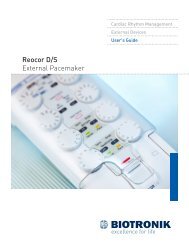
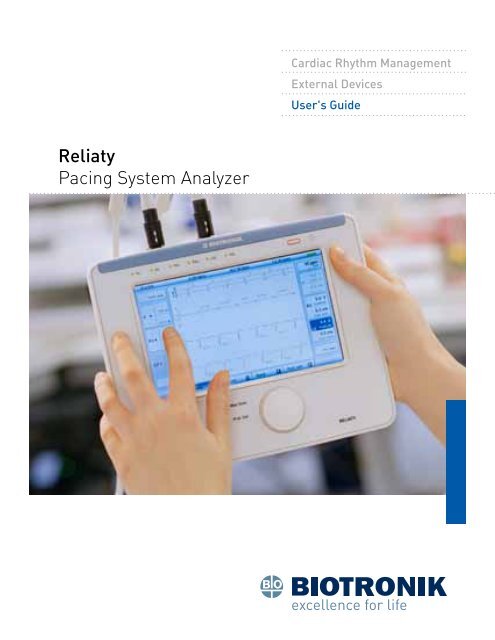
Cardiac Rhythm Management<br />
External Devices<br />
User's Guide<br />
<strong>Reliaty</strong><br />
<strong>Pacing</strong> <strong>System</strong> <strong>Analyzer</strong>
1<br />
Table of Contents<br />
Indications/Contraindications/Warnings/Precautions/<br />
General Safety Instructions....................................................................3<br />
Overview............................................................................................... 18<br />
<strong>System</strong> Overview.................................................................................. 19<br />
Starting <strong>Reliaty</strong>.................................................................................... 20<br />
Connecting to <strong>Reliaty</strong>........................................................................... 22<br />
External Monitor......................................................................................22<br />
Patient Cables.........................................................................................23<br />
User Interface...................................................................................... 24<br />
Buttons....................................................................................................24<br />
Graphical Interface..................................................................................26<br />
Channel Selection...................................................................................29<br />
Testing.................................................................................................. 30<br />
Sensing....................................................................................................30<br />
Threshold and Impedance......................................................................31<br />
Conduction and Wenckebach..................................................................32<br />
Burst <strong>Pacing</strong>............................................................................................34<br />
Maximum <strong>Pacing</strong>.....................................................................................35<br />
Safe Program....................................................................................... 36<br />
Print and Export................................................................................... 37<br />
Report Screen..........................................................................................37<br />
Report List...............................................................................................38<br />
Device Settings..................................................................................... 40<br />
Preferred Settings...................................................................................40<br />
<strong>System</strong> Settings.......................................................................................41<br />
Visual and Audio Signals...................................................................... 43<br />
Patient Cables...................................................................................... 44<br />
Power Supply........................................................................................ 45<br />
Battery Exchange....................................................................................46<br />
Power Supply Management....................................................................47<br />
Technical Specifications....................................................................... 49<br />
Cleaning...................................................................................................49<br />
Device Specifications..............................................................................49<br />
Specifications/<strong>System</strong> Messages/Symbols.......................................... 53
3 Indications and Contraindications for Use<br />
Note: Federal (<strong>USA</strong>) law restricts this device to sale by, or on<br />
the order of, a physician (or properly licensed practitioner).<br />
Indications / Contraindications /<br />
Warnings / Precautions / General<br />
Safety Instructions<br />
Indications for Use:<br />
The <strong>Reliaty</strong> pacing system analyzer is indicated for use<br />
in pacing lead system analysis during the implantation of<br />
pacemakers and defibrillators.<br />
Note: During implantation of cardiac pacemaker and ICD<br />
systems, the device does not measure shock impedance and<br />
defibrillation threshold (DFT).<br />
Intended Use<br />
The <strong>Reliaty</strong> is intended to be used during the implantation of<br />
pacemakers and defibrillators to evaluate the placement and<br />
integrity of pacing leads and to determine the appropriate<br />
pacing parameters for the implanted device.<br />
Only trained medical personnel may use the device. While<br />
the device is in use, the medical staff must continuously<br />
monitor the patient with the aid of a surface ECG monitor,<br />
and always have cardiac emergency equipment (e.g., external<br />
pacemaker, defibrillator) in an operational status available<br />
for immediate life support. Consider additional pre-emptive<br />
measures in patients where loss of pacing could cause lifethreatening<br />
danger.<br />
In support of this intended use, the device provides the<br />
following measurement/diagnostic capabilities:
4 Indications and Contraindications for Use<br />
• For the sensing of intrinsic events of the heart:<br />
--<br />
P/R wave amplitudes and slew rate<br />
--<br />
Rates (PP, RR interval)<br />
--<br />
Intrinsic AV delay (PR interval)<br />
--<br />
Conduction times<br />
--<br />
Wenckebach point<br />
--<br />
VV delay<br />
• For the pacing of the heart:<br />
--<br />
<strong>Pacing</strong> threshold in up to 3 chambers<br />
--<br />
Lead impedances<br />
--<br />
Burst pacing<br />
Note: The device may not be used as a life-support system.<br />
During the implantation, the device is suitable for temporary<br />
external pacing in up to three chambers while the medical<br />
staff must continuously monitor the patient with the aid of a<br />
surface ECG monitor.<br />
Contraindications:<br />
The following applications are contraindicated:<br />
• With AV conduction disorders:<br />
--<br />
Atrial single-chamber pacing<br />
• With competing intrinsic rhythms:<br />
--<br />
Asynchronous modes<br />
• With chronic atrial tachycardia as well as chronic atrial<br />
fibrillation or flutter:<br />
--<br />
Modes with atrial control (DDD, VDD)<br />
• With poor tolerance of high ventricular rates (e.g., with<br />
angina pectoris):<br />
--<br />
Tracking modes (i.e., atrial control modes) and<br />
propensity for atrial tachycardia<br />
• Use as an external pacemaker outside of the<br />
implantation procedure.
5<br />
Indications and Contraindications for Use<br />
Possible Complications<br />
Depending on the patient's condition and depending on the<br />
scope and type of pacing program, the following possible<br />
complications associated with the use of pacing system<br />
analyzers are reported in medical references: life-threatening<br />
atrial and ventricular arrhythmia, bradycardia, tachycardia,<br />
and asystole.<br />
Warnings:<br />
Danger from loss of power<br />
Operating the device with depleted batteries, unapproved<br />
battery types or no batteries can endanger the patient if linepower<br />
is temporarily interrupted.<br />
• Do not use the device with depleted batteries, unapproved<br />
battery types, or when the battery magazines are not fully<br />
populated with batteries.<br />
When the battery level indicator is red, the device has less<br />
than 30 minutes of remaining battery service time.<br />
• For additional patient safety connect the external power<br />
supply at this point.<br />
• When operating on battery power, do not attempt to<br />
replace the batteries in either battery magazine when the<br />
battery level indicator is red.<br />
• Do not plug in a USB device or attach an external VGA<br />
monitor when the battery level indicator is red.<br />
Fatal injury if exposed to fluids<br />
Before cleaning and disinfecting device surfaces, disconnect<br />
the external power supply.
6<br />
Indications and Contraindications for Use<br />
Danger of explosion if exposed to cleaning and<br />
disinfecting agents<br />
Before operating the device, let cleaning and disinfection<br />
agents evaporate.<br />
Danger from contamination<br />
The device cannot be sterilized.<br />
• Do not allow the device to enter a sterile area.<br />
Danger from loss of pacing support<br />
After the device is switched on, the pacing functions are<br />
switched off for approximately 15 seconds while a self-test is<br />
conducted, so that no pacing is possible in this time.<br />
• Keep a separate pacing device ready for emergencies.<br />
Single chamber atrial modes are contraindicated for patients<br />
with impaired AV conduction.<br />
• If the patient has impaired AV conduction, a Wenckebach<br />
test must not be performed.<br />
Connecting the patient cable to the wrong lead may result<br />
in ineffective sensing and pacing behavior and loss of<br />
pacing support.<br />
• Verify that the RV patient cable is connected to the RV<br />
lead before selecting cross-chamber LV pacing.<br />
Danger from electrical leakage currents<br />
Electrical currents can be dangerous to the patient.<br />
• Never touch the patient and the device's electrical<br />
contacts at the same time.<br />
Danger from electrostatic charges<br />
The lead system is in electrical contact with the patients’<br />
heart and blood. Touching the metal clips on the patient cable<br />
or the pacing lead may induce dangerous electrical currents
7<br />
Indications and Contraindications for Use<br />
in the patient’s heart.<br />
• Do not touch the metal clips on the patient cable or the<br />
pacing lead.<br />
Electrical currents can be dangerous to the patient.<br />
• Discharge any electrical static charge on your person before<br />
touching the patient, the patient cables or the device.<br />
Danger from loss of function<br />
Moisture from wet cable can impair cable function and<br />
endanger the patient.<br />
• Do not use wet cables.<br />
Incorrect positioning of the protective sleeves over the cable<br />
clip(s) can cause unintended electrical connections that can<br />
impair cable function and endanger the patient.<br />
• Before connecting cables ensure correct position of<br />
protective sleeves.<br />
Danger from allergic reaction<br />
The contact of the cable and open wounds may result in<br />
allergic reaction of the patient.<br />
• Do not allow the cable to come into contact with an open<br />
wound.<br />
Danger from electrical currents<br />
Unused cable connections can induce electrical currents into<br />
the patient's heart.<br />
• Attach unused cable connections close to the patient.<br />
Danger from defibrillation<br />
While the device is designed and tested to be defibrillator<br />
safe, the patient can be endangered and the device can be<br />
damaged.
8<br />
Indications and Contraindications for Use<br />
• Whenever possible disconnect the device from the patient<br />
when defibrillating.<br />
• If the device is connected to the patient during<br />
defibrillation, check its operations afterwards.<br />
Danger from HF surgery<br />
The device is equipped with protective circuitry to prevent<br />
damage when used with HF surgery. Although this circuitry<br />
has been tested to and exceeds standard requirements, its<br />
efficiency is limited and depends on the strength, waveform,<br />
and conduction path of the induced current.<br />
In addition, use of HF surgery may induce dangerous<br />
currents into the patient cables which may be conducted<br />
into patient’s heart.<br />
Therefore:<br />
• Disconnect the patient cables from the device when<br />
performing HF surgery procedures.<br />
• Check the operations of the device if HF surgery has<br />
been used.<br />
Danger from abruptly terminating pacing<br />
Abruptly terminating pacing may result in extended periods<br />
of asystole in some patients.<br />
• Gradually decrease the pacing rate until the patient's<br />
intrinsic rate is detected for a controlled transition from<br />
pacing to intrinsic action.<br />
Danger from loss of capture<br />
<strong>Pacing</strong> threshold testing implies loss of capture. At loss of<br />
capture, asystole and pacing during vulnerable periods<br />
can occur.<br />
• Consider the health of the patient prior to performing a<br />
pacing threshold test.
9<br />
Indications and Contraindications for Use<br />
Danger from induction<br />
Always have cardiac emergency equipment (e.g., external<br />
pacemaker, defibrillator) in an operational status available<br />
for immediate life support. Consider additional pre-emptive<br />
measures in patients where loss of pacing could cause lifethreatening<br />
danger. Only activate the burst pacing when all<br />
necessary provisions have been made.<br />
Precautions:<br />
Functional impairment due to external damage.<br />
Mechanical impact, for example dropping the unit –<br />
unpackaged, from a height of over 5 cm (2 inches) – can<br />
permanently impair the function of the system.<br />
• Do not use the device if there is apparent damage.<br />
• If damage has occurred, contact <strong>BIOTRONIK</strong> to test, and<br />
if necessary, repair the device.<br />
Danger from unauthorized modification of the equipment<br />
Modification of the device or its accessories may place the<br />
health and safety of the operator and/or patient at risk.<br />
• Do not modify the device or its accessories.<br />
Damage by cleaning agents<br />
Do not use strong, abrasive cleaning agents or other organic<br />
solvents such as ether or benzine. These agents corrode the<br />
surface of the device.<br />
General Safety Instructions:<br />
Technical Manual<br />
The device may be used only in accordance with this<br />
technical manual.<br />
Risks of improper handling<br />
Disregarding the safety warnings can endanger the patient,
10<br />
Indications and Contraindications for Use<br />
the user, or others, as well as the equipment.<br />
Note: Failure to observe the safety precautions voids all<br />
damage claims and manufacturer liability.<br />
The following dangers may arise in the event of improper use:<br />
• Failure of important device functions.<br />
• Personal endangerment due to electrical effects.<br />
No modification of equipment<br />
Do not modify the device or its accessories. Modifications<br />
may put the health and safety of the operator and/or patient<br />
at risk.<br />
Physician supervision<br />
The device may only be operated under the constant<br />
supervision of a physician. During a procedure, the patient<br />
must be continuously monitored by medical personnel with<br />
the aid of a surface ECG monitor.<br />
Emergency equipment<br />
During the procedure, always have emergency resuscitation<br />
equipment (e.g., external pacemaker, defibrillator) in an<br />
operational status available for immediate life support.<br />
Consider additional pre-emptive measures in patients where<br />
loss of pacing could cause life-threatening danger.<br />
External pacing<br />
The device may not be used as a life-support system. During<br />
the duration of the implantation, the device is suitable<br />
for temporary external pacing while the patient is being<br />
continuously monitored by medical personnel.<br />
Touching clips of cables and leads<br />
Do not touch the metal clips on the patient cable or the<br />
pacing lead. The device is in electrical contact with the<br />
patient's heart and blood via the implanted leads. Touching
11<br />
Indications and Contraindications for Use<br />
the metal clips on the patient cable or the pacing lead may<br />
expose the patient's heart to dangerous electrical currents.<br />
Connecting cables to leads<br />
Verify that RV patient cable is connected to the RV lead before<br />
selecting cross-chamber LV pacing polarities. Connecting<br />
the patient cable to the wrong lead may result in ineffective<br />
sensing and pacing behavior and loss of pacing support.<br />
Patient cables<br />
Patient cables should not be connected to the device before<br />
it has reached the ready-for-operation status. After the<br />
device is "ready-for-operation", securely attach all patient<br />
cable connections.<br />
Wet cables<br />
Do not use wet cables.<br />
Cables and wounds<br />
Do not allow the cable to come into contact with an<br />
open wound.<br />
Unused cable connections<br />
Attach unused cable connections close to the patient.<br />
Protective sleeves of cables<br />
Before connecting cables ensure correct position of<br />
protective sleeves.<br />
Liquids<br />
Avoid spilling liquids on the device or its accessories. While<br />
the device is designed for limited protection against the<br />
ingress of particulate matter, it is not protected against the<br />
ingress of fluids.<br />
Electrostatic potentials<br />
Avoid delivering dangerous electrostatic shocks to the patient<br />
or equipment. Before handling the device, the patient cable or
12<br />
Indications and Contraindications for Use<br />
the corresponding leads, the electrostatic potential between<br />
physician or medical technicians and the patient must be<br />
equalized, for instance by touching the patient at a point as<br />
far as possible from the leads.<br />
Leakage currents<br />
Avoid leakage currents between all connected devices, the<br />
patient cable, and the patient if line-powered devices are<br />
used in the vicinity of the patient. Such leakage currents may<br />
trigger lethal arrhythmias.<br />
Potential equalization cables, if present, must be attached to<br />
all connected components.<br />
National and international regulations concerning the use of<br />
electromedical devices also apply to patient cables.<br />
Self-test<br />
Be aware that the when the device is turned on, it performs<br />
an internal self-test for approximately 15 seconds. During<br />
this time the device's pacing outputs are inactive and the<br />
device is unavailable for use.<br />
<strong>Pacing</strong> threshold test<br />
Consider the health of the patient prior to performing a<br />
pacing threshold test. A loss of capture, asystole and pacing<br />
during vulnerable periods can occur.<br />
Termination of pacing<br />
Do not abruptly terminate pacing. The sudden termination<br />
of pacing can lead to extended periods of asystole in some<br />
patients. Gradually decrease the pacing rate until the<br />
patient's intrinsic rate is detected.<br />
External ECG device<br />
During the implantation, the medical staff must continuously<br />
monitor the patient with the aid of a surface ECG monitor.
13<br />
Indications and Contraindications for Use<br />
<strong>Pacing</strong> mode selection<br />
Select a pacing mode that is consistent with the patient<br />
cable connections to the leads. Loss of pacing may be a<br />
consequence of inconsistent selection and may cause lifethreatening<br />
danger to the patient.<br />
Wenckebach test<br />
Because atrial single chamber pacing is contraindicated for<br />
use in patients with no AV conduction, the Wenckebach test<br />
may not be performed on such patients.<br />
Burst pacing<br />
Burst pacing can induce or accelerate dangerous arrhythmias.<br />
Always have cardiac emergency equipment (e.g., external<br />
pacemaker, defibrillator) in an operational status available<br />
for immediate life support when using this feature. Consider<br />
additional pre-emptive measures in patients where loss of<br />
pacing could cause life-threatening danger.<br />
High-frequency surgery<br />
The device is equipped with protective circuitry to prevent<br />
damage when used with HF surgery. Although this circuitry<br />
has been tested to and exceeds standard requirements, its<br />
efficiency is limited and depends on the strength, waveform<br />
and conduction path of the induced current.<br />
In addition, use of HF surgery may induce dangerous<br />
currents into the patient cables which may be conducted<br />
into patient’s heart.<br />
Therefore:<br />
• Disconnect the patient cables from the device when<br />
performing HF surgery procedures.<br />
• Check the operations of the device if HF surgery has<br />
been used.
14<br />
Indications and Contraindications for Use<br />
Defibrillation<br />
While the device is designed and tested to be defibrillator<br />
safe, whenever possible, disconnect the device from the<br />
patient when defibrillating. If the device is attached during<br />
defibrillation, check its operations afterwards.<br />
Basic advice<br />
Only the manufacturer may perform corrective maintenance,<br />
enhancements or modifications to the device.<br />
Connecting accessories<br />
Do not connect a USB flash memory stick, a Bluetooth<br />
adapter or an external VGA monitor while the device is<br />
operating on low battery power (i.e., when the battery gauge<br />
is displayed red). Connecting one of these devices may cause<br />
a sudden increase in power consumption and cause the<br />
device to prematurely shut off.<br />
Sensitivity<br />
Electromagnetic interference may cause noise on the IEGM<br />
traces and spurious sense events and as a consequence may<br />
influence the timing of the pacing delivered to the patient.<br />
Lower sensitivity settings increase the susceptibility of<br />
the device to interfere with electromagnetic fields of other<br />
devices or equipment. A sensitivity setting at or above 1 mV is<br />
strongly recommended, if clinically suitable.<br />
Replacement parts and accessories<br />
Ensure safety compliance by using only original replacement<br />
parts and accessories authorized by <strong>BIOTRONIK</strong>. Using any<br />
other parts voids the liability for subsequent events, the<br />
guarantee, and the warranty.<br />
Defects<br />
Do not put defective or damaged devices into operation.
15 Indications and Contraindications for Use<br />
Installation site<br />
The device may only be operated in an environment that<br />
meets the following conditions:<br />
• The ambient temperature, relative humidity and<br />
atmospheric pressure are within the specified operating<br />
conditions.<br />
• Sterile operating conditions can be maintained.<br />
• There are no explosive gases in the vicinity of the device.<br />
• There is always a cardiac emergency equipment (e.g.,<br />
external pacemaker, defibrillator) in an operational status<br />
available for immediate life support. Consider additional<br />
pre-emptive measures in patients where loss of pacing<br />
could cause life-threatening danger.<br />
• The patient is monitored with a surface ECG monitor.<br />
The device should stand on a level, dry surface. It should<br />
be placed so that it cannot slide, especially when cables<br />
are connected.<br />
Cable and lead connections<br />
• Inspect cables prior to use. Replace cables if they are<br />
worn or damaged.<br />
• Arrange cables to avoid entanglement with equipment or<br />
medical staff.<br />
• Cable connections and plugs must be cleaned as defined<br />
in Cleaning on page 49 and Patient Cables on page 44.<br />
Soiled contacts can lead to signal distortions and<br />
false diagnoses.<br />
• All electrical contacts must be dry.<br />
• Make sure that cables are securely connected. When<br />
disconnecting cables from the device, clasp the locking<br />
connector and pull. Do not pull on the cable.<br />
• All lead connections are swap-safe and encoded at the<br />
lead connectors. Do not force cables to connect together<br />
or force lead connectors into the connector ports.
16<br />
Indications and Contraindications for Use<br />
Note: Before connecting the patient cable to the leads,<br />
ensure that the leads are securely implanted in the<br />
patient’s heart.<br />
• Patient cables may only be used by healthcare<br />
professionals that are qualified for intracardial<br />
examinations and therapy.<br />
• Precautionary measures must be maintained while<br />
conducting an intracardial examination. Use in suitable<br />
rooms featuring X-ray facility and cardiac emergency<br />
equipment (e.g., external pacemaker, defibrillator) in an<br />
operational status available for immediate life support.<br />
Consider additional pre-emptive measures in patients<br />
where loss of pacing could cause life-threatening danger.<br />
• No patient cables should be connected to the device<br />
before it has reached the ready-for-operation status.<br />
Current parameter settings should be verified, prior to<br />
connecting the patient cables to the device.<br />
Note: It is possible to connect or disconnect the patient<br />
cables while the device is on.<br />
Possible electromagnetic interferences<br />
When used with its approved accessories and configure and<br />
operated in accordance with the instruction in this document,<br />
this device meets the electromagnetic compatibility<br />
requirements of IEC 60601-1-2.<br />
However, strong electromagnetic interference can occur in<br />
close proximity to other electrical equipment. Therefore the<br />
device should not be placed adjacent to or stacked on other<br />
electrical equipment.<br />
Electromagnetic interference may cause interference with<br />
the device, including:
17<br />
Indications and Contraindications for Use<br />
• Resetting of the device.<br />
• Noise on the IEGM traces, spurious sense events.<br />
If electromagnetic interference occurs, try the following, as<br />
appropriate:<br />
• Switching off the source of interference.<br />
• Moving the source of interference away from the device.<br />
• Disconnecting any electrical connections between the<br />
device and the source of interference.<br />
• Switching the device off and back on, again.<br />
• If the interference continues, contact your local<br />
<strong>BIOTRONIK</strong> representative immediately.<br />
Note:<br />
• Portable and mobile RF communication equipment can<br />
affect the operation of the device.<br />
• Use of accessories that are not approved by <strong>BIOTRONIK</strong><br />
can increase the device’s electromagnetic emissions and/<br />
or electromagnetic susceptibility.<br />
Note: Electromagnetic interference may cause noise<br />
on the IEGM traces and spurious sense events and as a<br />
consequence may influence the timing of the pacing delivered<br />
to the patient. Lower sensitivity settings increase the<br />
susceptibility of the device to interfere with electromagnetic<br />
fields of other devices or equipment. A sensitivity setting at or<br />
above 1 mV is strongly recommended, if clinically suitable.<br />
Note: Prolonged exposure to electromagnetic interference<br />
may cause the device to pace asynchronously.
18 Overview<br />
Overview<br />
<strong>Reliaty</strong> is a portable medical diagnostic device intended<br />
to be used during the implantation of pacemakers and<br />
defibrillators to evaluate the placement and integrity of<br />
pacing leads and to determine the appropriate pacing<br />
parameters for the implanted device.<br />
The user controls the operations of <strong>Reliaty</strong> through the LCD<br />
touch-screen, parameter wheel, and control buttons. Figures<br />
1 and 2 provide an overview of external features. The device<br />
provides three-chamber pacing and sensing and can display<br />
up to three channels of real-time IEGMs and markers. The<br />
device provides standard PSA functionality, including lead<br />
impedance measurements, intrinsic amplitude, timing<br />
measurements, and pacing thresholds. It has a report feature<br />
that provides a summary of device measurements, along with<br />
optional IEGM traces.
19 <strong>System</strong> Overview<br />
<strong>System</strong> Overview<br />
Connectors for patient cables<br />
Secondary power<br />
Tilt stand<br />
AC power<br />
VGA interface<br />
USB port<br />
Figure 1: <strong>Reliaty</strong> PSA<br />
LED indicators<br />
Safe program<br />
Measurement<br />
keys<br />
Maximum stimulation<br />
Preferred settings<br />
Parameter wheel<br />
Figure 2: <strong>Reliaty</strong> PSA front panel
20 Starting <strong>Reliaty</strong><br />
Starting <strong>Reliaty</strong><br />
Check battery cartridges and power supply before turning the<br />
device on. The ON/OFF button is located on the right side of<br />
the device. Press the ON/OFF button to turn on <strong>Reliaty</strong>. The<br />
start screen appears shortly after the device is turned on. A<br />
self-test then runs for approximately 15 seconds. After the<br />
self-test, the device is ready for use. To turn the device off,<br />
press the ON/OFF button again.<br />
Checkup prior to use<br />
• Perform a checkup on the device and the approved<br />
accessories before each use:<br />
--<br />
Inspect the housing for mechanical damage,<br />
dents, loose parts, cracks or tampering.<br />
--<br />
Inspect the legibility of the labeling.<br />
--<br />
Inspect cables for damage to the insulation,<br />
connectors or electrical contacts.<br />
--<br />
Replace damaged or worn cables.<br />
--<br />
Turn the device on.<br />
--<br />
Verify that all indicator lights flash briefly.<br />
--<br />
Wait 15 seconds to allow an internal self-test to<br />
complete.<br />
--<br />
Verify that no error messages are displayed.<br />
• If the device has mechanical damage or does not pass its<br />
internal self-test, do not use the device and contact your<br />
local <strong>BIOTRONIK</strong> representative immediately.
21 Starting <strong>Reliaty</strong><br />
Periodic Inspection<br />
• A complete inspection of the device needs to be<br />
performed:<br />
--<br />
in suspicion of malfunction;<br />
--<br />
every two years.<br />
• Excessive electrical power, e.g. combined use of HF<br />
surgery equipment or a defibrillator on a patient<br />
during use of the pacing system analyzer, may damage<br />
the device. Check the operation of the device after<br />
such usage and initiate this inspection if any signs of<br />
malfunction exist, especially if failure messages during<br />
start-up self-test occur on the display.<br />
• This inspection needs to be performed according to<br />
manufacturer’s instructions. These instructions can be<br />
provided on demand and state all required test steps and<br />
devices related to the check.<br />
• If you have any questions, please contact your local<br />
<strong>BIOTRONIK</strong> representative.
22 Connecting to <strong>Reliaty</strong><br />
External<br />
Monitor<br />
Connecting to <strong>Reliaty</strong><br />
Figure 3: <strong>Reliaty</strong> VGA port<br />
It is possible to connect or disconnect an external monitor<br />
while the device is on. Connect the VGA plug of the monitor<br />
to the VGA port, as shown in Figure 3. If the VGA port is set<br />
to Auto and <strong>Reliaty</strong> detects a connection to a VGA monitor,<br />
<strong>Reliaty</strong> will enable its external VGA port. The device may<br />
not detect some VGA monitors, so it may be necessary<br />
to manually enable the external port. For instructions<br />
on enabling or disabling this feature, refer to the Device<br />
Settings section on page 40.
23 Connecting to <strong>Reliaty</strong><br />
Patient<br />
Cables<br />
Figure 4: Patient cables port<br />
For a list of compatible cables, see the Patient Cables<br />
section on page 44.<br />
Connect to right side of the heart<br />
• To connect to the right side of the heart (RA/RV), insert<br />
the patient cable’s locking connector into port ,<br />
shown in Figure 4.<br />
• Ensure that the plug has locked into the port.<br />
• Connect the patient connections of the patient cable or<br />
adapter to the RA/RV leads of the patient.<br />
Connect to the left side of the heart<br />
• To connect to the left side of the heart (LV), insert the<br />
patient cable’s locking connector into port , shown<br />
in Figure 4.<br />
• Ensure that the plug has locked into the port.<br />
• Connect the patient connections of the patient cable or<br />
adapter to the LV leads of the patient.<br />
Remove the cables<br />
• Disconnect the patient cable or adapter from the pacing<br />
lead by opening the clips and removing the pacing lead.<br />
• Disconnect the patient cable from <strong>Reliaty</strong> by pulling on<br />
the cable’s locking connector.
24 User Interface<br />
User Interface<br />
Buttons<br />
Figure 5: User interface and buttons<br />
LEDs: The LEDs, shown in Figure 5, along the top of the<br />
front panel indicate pacing or sensing in each of the three<br />
chambers. See Visual and Audio Signals section on page 43<br />
for more information.<br />
VVI: Selecting the red button to the left of will start<br />
pacing in the safe program immediately, which is VVI at 60<br />
bpm. For more information on safe program, see the Safe<br />
Program section on page 36.
25 User Interface<br />
Parameter wheel: To adjust a selected parameter, turn<br />
the wheel to the right or left. The new values are effective<br />
immediately. To increment the value, turn the wheel<br />
clockwise. To decrement the value, turn the wheel<br />
counter-clockwise.<br />
Max Stim: This button delivers pacing at 10 V at 2.0 ms. For<br />
more information, see the Maximum <strong>Pacing</strong> section on page 35.<br />
Pref. Set.: This button activates the user-defined preferred<br />
settings. See the Preferred Settings section on page 40 for<br />
more information.<br />
Measurement keys: Pressing the Sensing, Threshold, or<br />
Impedance key will save the current measured value in the<br />
selected channel to the report. See the Testing section on<br />
page 30 for more information.<br />
Timing/Freeze: Pressing the Timing/Freeze key will open the<br />
Freeze window, which displays the most recent IEGM. See<br />
the Testing section on page 30 for more information.
26 User Interface<br />
Graphical<br />
Interface<br />
Figure 6: User interface<br />
Information bar: Along the top of the screen, the current<br />
mode, rate in each channel, and power supply indicator are<br />
displayed to provide basic information.<br />
Modes: Pressing the Mode button opens a drop down menu<br />
with common single- and dual-chamber modes. The Mode<br />
button is indicated by the black rectangle in Figure 6.<br />
Sensing button: Pressing the Sense button, available in<br />
each chamber, toggles to ON or OFF to adjust the mode to<br />
enable or disable sensing in a particular chamber. When<br />
sensing is ON in a particular channel, the circle on the<br />
button is filled in. When sensing is OFF in a particular<br />
channel, the circle is not filled. The Sense button is marked<br />
by the blue rectangle in Figure 6.
27 User Interface<br />
<strong>Pacing</strong> button: Pressing the Pace button, available in each<br />
chamber, toggles to ON or OFF to adjust the mode to enable<br />
or disable pacing in a particular chamber. Like the Sense<br />
button, the Pace button indicates whether pacing is ON or<br />
OFF in a particular channel using a filled in or empty circle.<br />
The Pace button is marked by the red rectangle in Figure 6.<br />
Channel button: Pressing a channel button activates or<br />
deactivates each channel. When deactivated, the channel<br />
will be grayed out. The Channel button is indicated by the<br />
green rectangle in Figure 6.<br />
Tracking button: Pressing the Tracking button will switch the<br />
mode between a tracking mode and a non-tracking mode<br />
(e.g., DDD to DDI). The Tracking button is indicated by the<br />
yellow rectangle in Figure 6.<br />
Tests: Selecting the Tests button will send the user to the<br />
Tests screen to perform basic lead tests. See page 30 for<br />
more information on testing.<br />
Report: Selecting the Report button will send the user to<br />
the Report screen to view, export, or print a measurement<br />
report. See page 37 for more information on reports.<br />
Burst: Selecting the Burst button will send the user to the<br />
Burst pacing screen to perform high rate pacing. See page 34<br />
for more information on burst pacing.<br />
Pref. set.: Selecting the Pref. set. button will send the user<br />
to the Preferred Settings screen to view or change system<br />
settings and user-defined settings. See page 40 for more<br />
information on preferred settings.
28 User Interface<br />
Basic rate: Selecting the Rate button will allow the user<br />
to increase or decrease the basic rate by adjusting the<br />
parameter wheel. The Rate button is indicated by the orange<br />
rectangle in Figure 6.<br />
Amplitude and pulse width: Selecting the Amplitude or Pulse<br />
Width buttons, available in each chamber, allows the user<br />
to adjust the output by adjusting the parameter wheel. The<br />
Amplitude and Pulse Width buttons are indicated by the<br />
purple rectangle in Figure 6. If a chamber is not pacing due to<br />
the current mode, the output buttons for that chamber will be<br />
grayed out, as shown by the LV channel in Figure 6. The user<br />
can still make changes to the amplitude and pulse width, but<br />
the chamber will remain grayed out and inactive.<br />
More: Selecting the More button opens the following<br />
additional adjustable parameters: AV delay, VV offset,<br />
sensitivity in each channel, and LV polarity.
29 User Interface<br />
Channel<br />
Selection<br />
Figure 7: Selecting a Channel<br />
<strong>Reliaty</strong> is capable of testing in three channels: atrium, right<br />
ventricle, and left ventricle. Each channel can be inactive,<br />
active, or selected.<br />
Inactive: The channel is not being tested and is not used in<br />
the current mode. Its inactivity is indicated by a grayed out<br />
appearance. The output on this channel can still be adjusted,<br />
and the new output will be in effect when the channel is<br />
activated again. In Figure 7, the LV channel is inactive.<br />
Active: The channel will have an associated IEGM and will no<br />
longer be grayed out. To activate an inactive channel, select<br />
the associated channel button. In Figure 7, the RV and A<br />
channels are active.<br />
Selected: Only one active channel can be selected at a time.<br />
To conduct and save measurements for a channel, the<br />
associated channel must be selected. When pressing one<br />
of the measurement buttons on the front panel, only the<br />
measurements of the selected channel are saved. In Figure 7,<br />
the A channel is active and selected.
30 Testing<br />
Sensing<br />
Testing<br />
All tests can be performed from the Tests screen, accessible<br />
by pressing the Tests button, located along the bottom of<br />
the <strong>Reliaty</strong> screen.<br />
Figure 8: P/R wave amplitude measurements in <strong>Reliaty</strong><br />
P/R wave amplitude measurements are used to assess the<br />
ability of the implanted device to sense the intrinsic activity<br />
of the heart at the current lead position within the heart. If<br />
the intrinsic heart rate of the patient is above the set pacing<br />
rate or pacing is disabled, the heart’s intrinsic activity can<br />
be measured. See below for instructions on performing a<br />
sensing test.<br />
• Select the desired channel.<br />
• Press the Sense button to adjust the mode to allow for<br />
sensing in that channel.<br />
• Adjust the mode, rate, and AV delay to promote intrinsic<br />
activity. Sensed values are displayed on that channel’s<br />
IEGM, as shown in Figure 8.
31 Testing<br />
Threshold<br />
and<br />
Impedance<br />
• Press the Sensing button on the front panel to save<br />
the displayed sensing measurements on the selected<br />
channel and a 5-second IEGM to the report.<br />
• Repeat the procedure for other channels as necessary.<br />
Figure 9: Threshold and impedance measurements in <strong>Reliaty</strong><br />
<strong>Pacing</strong> threshold measurements are used to assess the<br />
ability of the implanted device to effectively and efficiently<br />
pace the heart at the current lead position. Lead impedance<br />
measurements are used in assessing the integrity of the<br />
lead and the connection of the lead’s electrodes with the<br />
myocardium. A lead impedance measurement is made on<br />
each paced event. The last lead impedance measurement,<br />
in each channel, is displayed on the left-side of the IEGM<br />
window next to the IEGM trace for that channel, as shown<br />
with the red boxes in Figure 9. Also, the pacing amplitudes<br />
are displayed with their respective event on each channel’s<br />
IEGM, also shown in Figure 9. Perform the threshold and<br />
impedance measurements as follows:
32 Testing<br />
• Press the Channel button to activate and select the<br />
desired channel.<br />
• Press the Pace button to adjust the mode to allow pacing<br />
in that channel.<br />
• Adjust the rate and/or AV delay to force pacing in<br />
that channel.<br />
• Use the parameter wheel to decrease the pacing<br />
amplitude until loss of capture occurs.<br />
• Increase the pacing amplitude until capture is<br />
re-established.<br />
• Press the Threshold measurement key on the front<br />
panel to save the current pacing settings of the selected<br />
channel and save a 5-second IEGM to the report.<br />
• Use the parameter wheel to increase the pacing<br />
amplitude to a safe value (5 V to 10 V).<br />
• Press the Impedance measurement key on the front panel<br />
to save the displayed impedance measurement, the current<br />
pacing settings, and a 5-second IEGM to the report.<br />
Conduction<br />
and<br />
Wenckebach<br />
Figure 10: Freeze screen to allow timing measurements
33 Testing<br />
Conduction<br />
Conduction measurements are used to determine<br />
appropriate pacing parameters for the implanted device.<br />
Antegrade conduction time is measured by sensing in the<br />
ventricle and measuring from atrial event to ventricular<br />
sensed event. The retrograde conduction time is measured<br />
by pacing in the ventricles and measuring the time interval<br />
between the ventricular pace and any subsequently induced<br />
P-wave. Perform a conduction test as follows:<br />
• Adjust the mode and rate to allow for antegrade or<br />
retrograde conduction.<br />
• Press the Timing/Freeze key on the front panel, which will<br />
bring up the Timing/Freeze window, shown in Figure 10.<br />
• Adjust the slide bar to move the viewing window.<br />
• Use the calipers to make time-based measurements.<br />
• Use the grid to make amplitude-based measurements.<br />
• Press the Save button to save the strip to the report.<br />
Wenckebach<br />
The patient’s intrinsic Wenckebach point measurements<br />
are useful in determining the appropriate pacing settings<br />
for the implanted device. For instructions on measuring the<br />
Wenckebach point, see below.<br />
• Adjust the mode to allow for pacing in the atrium and<br />
sensing in the ventricle.<br />
• Increase the pacing rate until Wenckebach behavior is<br />
displayed on the IEGM.<br />
• Press the Timing/Freeze key.<br />
• Adjust the slide bar to move the viewing window.<br />
• Use the calipers to make time-based measurements.<br />
• Use the grid to make amplitude-based measurements.<br />
• Press the Save button to save the strip to the report.
34 Testing<br />
Burst<br />
<strong>Pacing</strong><br />
Figure 11: Burst pacing pop-up window<br />
Figure 12: Burst pacing screen<br />
Burst pacing can be used to terminate certain types of<br />
arrhythmias. During burst pacing, the currently selected<br />
channel is stimulated with a fixed pulse amplitude (7.5 V),<br />
fixed pulse width (1.0 ms), and an adjustable pacing rate.
35 Testing<br />
Maximum<br />
<strong>Pacing</strong><br />
Burst pacing is possible on all three channels, but with only<br />
one channel at a time. For instructions on performing burst<br />
pacing, see below.<br />
• Go to the Burst screen by pressing the Burst button from<br />
any other screen.<br />
• A window will pop up, as shown in Figure 11. Click OK.<br />
• Select the respective burst rate button to select the<br />
chamber where the burst pacing shall be applied, as<br />
shown in Figure 12.<br />
• Use the parameter wheel to adjust the burst rate.<br />
• Press the burst deliver button to apply burst pacing with<br />
the selected burst rate.<br />
The burst is delivered as long as the button is pressed.<br />
Maximum burst duration is 30 seconds. If the burst deliver<br />
button is held longer than 30 seconds, <strong>Reliaty</strong> will stop<br />
delivering burst pacing.<br />
While burst pacing in the atrium, the device will provide<br />
ventricular backup pacing if the pacing mode is a ventricular<br />
pacing mode when starting the burst. If the pacing mode is<br />
not a ventricular pacing mode, ventricular pacing support will<br />
not be provided.<br />
The Maximum pacing amplitude is used to assess whether<br />
the extracardiac muscle or phrenic nerve can be inadvertently<br />
stimulated by paces with the lead in its current position<br />
within the heart. During maximum pacing, the currently<br />
selected channel is paced with an output of 10 V at 2.0 ms.<br />
For instructions on delivering maximum pacing, see below.<br />
• Activate and select the desired channel.<br />
• Adjust the mode to allow pacing in this channel.<br />
• Deliver maximum pacing by pressing the Max Stim key on<br />
the front panel and holding it.<br />
• Terminate maximum pacing by releasing the Max Stim key.
36 Safe Program<br />
Safe Program<br />
The Safe program function sets critical pacing parameters<br />
to preset, safe values. The Safe program, when initiated,<br />
immediately interrupts all other <strong>Reliaty</strong> functions.<br />
The Safe program settings (non-programmable) are<br />
listed below:<br />
Mode:<br />
VVI RV<br />
Rate:<br />
60 bpm<br />
Output:<br />
7.5 V at 1.0 ms<br />
Sensitivity: 2.5 mV<br />
Refractory Period: 250 ms<br />
To deliver the Safe program, press the Safe program key<br />
on the front panel. The Safe program is immediately active<br />
without any other confirmation. To change the Safe program<br />
parameters back to their original values, select each<br />
parameter and use the parameter wheel on the front panel to<br />
make the adjustments or press the Pref. set. key on the front<br />
panel to activate preferred settings.
37 Print and Export<br />
Report<br />
Screen<br />
Print and Export<br />
Figure 13: Report screen<br />
To print or export a report, navigate to the Report screen by<br />
selecting the Report button along the bottom of the <strong>Reliaty</strong><br />
screen, as shown in Figure 13. To view a detailed report with<br />
both measured values and 5 second snapshots of the IEGM<br />
window, press the Details button.<br />
To export a PDF, connect a USB flash drive to the USB port.<br />
The Report screen will display measurements from the<br />
current report. From the Report screen, select the Print/<br />
Export button. A pop-up window will show export options.<br />
Select the USB to export the report to the USB drive.<br />
To print a report to an external Bluetooth ® printer, connect<br />
a Bluetooth ® module to the USB port. The Report screen<br />
displays a summary of the measurements saved in the<br />
current report. Press the Print/Export button. A pop-up<br />
window will show export options. Select the printer to<br />
print the report.
38 Print and Export<br />
Report<br />
List<br />
Press the Details button to see the associated IEGM strips.<br />
Press the Print/Export button to print or export the report<br />
with all details.<br />
Figure 14: Report list<br />
To manage the reports, go the Reports screen. Press the<br />
Report List button to see the list of all stored reports, as<br />
shown in Figure 14.<br />
View a report: Select an entry from the list and press the View<br />
Report button to display a report.<br />
Name a report: Select an entry from the list and press the<br />
Rename Report button to rename a report. Use the screen<br />
keyboard to change the name of the report.<br />
Create a report: Press the New Report button to add a new<br />
report. All following measurements will be saved to this<br />
report until a new report is created or <strong>Reliaty</strong> is turned off.
39 Print and Export<br />
Edit a report: To store new measurements on an existing<br />
report, select the report from the list. The report is then<br />
marked blue and all further testing and additional testing<br />
measurements will be stored in this report. This is useful for<br />
documenting different configurations during implant or to<br />
store more than one Freeze screen per implantation. <strong>Reliaty</strong><br />
allows the user to store one Freeze screen per report to<br />
document timing. A new Freeze screen recorded overwrites<br />
the previously saved Freeze screen.<br />
Up to 15 reports can be stored in the Report list. Each report<br />
is displayed in the Report list with date and time or a name.<br />
Once 15 reports have been stored and a new report is added,<br />
the oldest report is automatically deleted. The Report list<br />
remains stored when the device is switched off.
40 Device Settings<br />
Device Settings<br />
Figure 15: Preferring settings<br />
Preferred<br />
Settings<br />
Access the Preferred Settings screen by pressing the Pref.<br />
set. button on the screen. In this screen, the user can<br />
configure the pacing parameters (preferred settings) and the<br />
system settings such as date, time, language, or illumination<br />
as shown in Figure 15.<br />
<strong>Reliaty</strong> begins with the preferred parameters when it is<br />
initially turned on. To adjust these parameters, select the<br />
parameter and use the parameter wheel to change the value<br />
or select the new setting from a list. Use the slide bar to view<br />
the complete list of settings. As these settings are changed,<br />
the new system settings are effective immediately and no<br />
confirmation is required. Changes to preferred settings can<br />
be made without affecting current device operations. Any<br />
changes made to preferred settings will be saved.<br />
The preferred settings can be activated in the Tests screen by<br />
pressing the Pref. set. key on the front panel.
41 Device Settings<br />
<strong>System</strong><br />
Settings<br />
<strong>System</strong> settings are the general settings of the device. A change<br />
in the system settings can be made without affecting the current<br />
operation of the device. All changes to system settings are saved<br />
permanently in <strong>Reliaty</strong>, even after it is turned off.<br />
To change a system setting, select the Pref. set. button to<br />
move to the Preferred Settings page. Select the value and<br />
change it using the control knob on the front panel. The new<br />
value is immediately effective. From this screen, adjustments<br />
can be made to the following parameters: date, time, date<br />
format, language, and illumination.<br />
Illumination brightness: The illumination brightness of the<br />
display is preset to a basic value (Normal) to provide an<br />
optimal compromise between light intensity of the display<br />
and service time for battery operation. To change the<br />
illumination brightness on the Pref. set. screen, press the<br />
Illumination button repeatedly to activate one of the following<br />
settings: Normal, Bright, Long life. Note: The Bright setting<br />
will decrease battery life.<br />
Factory settings: All system settings can be reset to the<br />
factory default values. To reset all settings to factory values,<br />
press the Reset pref. settings button. The system settings<br />
are changed to the factory settings. The current operational<br />
settings are not affected by this change.<br />
VGA settings: To change the VGA settings, press the VGA<br />
button, seen in Figure 15, to switch among OFF, ON, and<br />
Auto detect (recommended). The auto detect setting will<br />
automatically turn on the VGA port when a VGA monitor<br />
connection is detected. If the device is not detecting the<br />
monitor, switch the VGA settings to ON. To conserve battery<br />
when not using a VGA monitor, switch to the VGA settings to OFF.
42 Device Settings<br />
Maintenance code: The Maintenance code is used for service<br />
purposes only.<br />
Export system logfile: This option is used during unexpected<br />
device behavior. A logfile is exported via a USB stick, and the<br />
exported information is then used for analysis.
43 Visual and Audio Signals<br />
Visual and Audio Signals<br />
<strong>Reliaty</strong> includes audio and visual signals to alert the user. These<br />
signals include a tone for confirmation of user input, a beep to<br />
warn for low battery, and LEDs to indicate pacing and sensing.<br />
Confirmation of user input: <strong>Reliaty</strong> emits audible signals to<br />
confirm user input. A high tone indicates a successful action<br />
that changes the behavior of <strong>Reliaty</strong>. A deep tone confirms<br />
the user input, but there is no direct effect if the action was<br />
not successful. For example, if changes are made to the<br />
output of an inactive channel, a deep tone will confirm that<br />
these changes were successful even though the changes do<br />
not directly affect current device function.<br />
Battery: <strong>Reliaty</strong> emits a beep every 20 seconds when the<br />
battery gauge is red (< 30 minutes of battery life remaining) to<br />
warn the user to switch to a different power source.<br />
LED: The LEDs along the top of the front panel indicate<br />
pacing and sensing in each channel. Each channel has two<br />
LEDs: a green LED to indicate sensing and a yellow LED to<br />
indicate pacing.
44 Patient Cables<br />
Patient Cables<br />
See Table 1 for a list of cables that are compatible<br />
with <strong>Reliaty</strong>.<br />
Cable Description Length Sterilization Cycles<br />
PK-141<br />
Alligator clips<br />
2.8 m<br />
(110.2 in)<br />
Re-sterilizable<br />
with steam at<br />
134°C<br />
50 cycles of<br />
re-sterilization<br />
PK-67-L<br />
and<br />
PK-67-S<br />
with<br />
adapters<br />
Alligator clips<br />
with PA-4 adapter;<br />
Connector for 2 mm<br />
pins with adapter<br />
PA-1-B; IS-1<br />
connector with PA-2<br />
adapter<br />
2.6 m (L)<br />
(102.4 in)<br />
and<br />
0.8 m (S)<br />
(31.5 in)<br />
Re-sterilizable<br />
with steam at<br />
121°C<br />
20 cycles of<br />
re-sterilization<br />
PK-67-L<br />
and<br />
PK-67-S<br />
with<br />
PK-155<br />
Alligator clips<br />
2 m<br />
(78.7 in)<br />
(PK-155)<br />
PK-155 is<br />
disposable<br />
and cannot be<br />
re-sterilized<br />
N/A<br />
Table 1: Cables compatible with <strong>Reliaty</strong>
45 Power Supply<br />
Power Supply<br />
Secondary power<br />
AC power<br />
Figure 16: Power supply<br />
<strong>Reliaty</strong> has a redundant power supply, which includes two<br />
separate battery cartridges (only one is shown in Figure 16)<br />
and an external power supply, as shown in Figure 16. The<br />
primary power source is the external power source, which can<br />
be attached while <strong>Reliaty</strong> is operating on secondary supply, i.e.,<br />
the batteries. When the external power supply is unavailable,<br />
the device automatically switches from the primary to the<br />
secondary power source without loss of function.<br />
<strong>Reliaty</strong> includes two battery cartridges, that serve as the<br />
secondary power source for the device. Each cartridge<br />
requires four disposable AA batteries. With Duracell MN 1500<br />
or Energizer E91 LR6 batteries, operating time with these<br />
batteries is at least 12 hours * when the batteries are new.<br />
Also, the batteries should be removed if <strong>Reliaty</strong> will not be<br />
used for a prolonged period of time to avoid draining battery<br />
life. Rechargeable batteries are contraindicated for <strong>Reliaty</strong><br />
because they do not allow for a precise calculation of the<br />
remaining operation time. Rechargeable batteries cannot be<br />
recharged via <strong>Reliaty</strong>.<br />
*<br />
With two chamber stimulation at 70 bpm, 5 V, 0.5 ms, 500 ohm and<br />
no external devices connected
46 Power Supply<br />
Battery<br />
Exchange<br />
Figure 17: Replacing <strong>Reliaty</strong> batteries<br />
Batteries can be replaced while the device is still in use<br />
and operates using the second battery cartridge or external<br />
power source. Battery replacement while the device is in use<br />
will not interrupt <strong>Reliaty</strong> operation when a second battery<br />
cartridge or external power source is also used. The battery<br />
compartments are located on the right and left side of the<br />
device. See below for instructions regarding replacing the<br />
batteries and refer to Figure 17.<br />
• Open the battery compartment by pushing up on the<br />
locking mechanism.<br />
• Pull the battery cartridge out.<br />
• Remove all old batteries. For optimal device performance,<br />
replace all four batteries at the same time with new<br />
batteries.<br />
• Insert the four new batteries as indicated by the terminal<br />
notations on the battery cartridge.<br />
• Push the battery cartridge into the battery compartment<br />
until the locking mechanism latch is heard.
47 Power Supply<br />
Power<br />
Supply<br />
Management<br />
To ensure operation of <strong>Reliaty</strong> during battery replacement,<br />
replace the batteries in the depleted cartridge first. <strong>Reliaty</strong><br />
comes with a third battery cartridge for quick<br />
battery exchange.<br />
Replace left<br />
cartridge<br />
Replace right<br />
cartridge<br />
Immediately connect the external power supply!<br />
Do not replace any battery cartridge.<br />
Figure 18: <strong>Reliaty</strong> Test screen with Power Supply Indicators<br />
The Power Supply Indicator displays the type of power supply<br />
and also indicates overall battery status. See Table 2 for a<br />
description of the different indicators and their meaning. The<br />
images on the lower left and right corners indicate which<br />
cartridge needs to be replaced, as shown in Figure 18. The<br />
images on the lower left and right corners are not used when<br />
the device is using an external power supply.
48 Power Supply<br />
Image<br />
Definition<br />
External power supply connected,<br />
batteries not used<br />
Remaining operation time is currently<br />
being calculated<br />
Using battery only, remaining operation<br />
time is longer than 4 hours<br />
Using battery only, remaining operation<br />
time is between 2 and 4 hours<br />
Using battery only, operation time is<br />
below 30 minutes<br />
Table 2: <strong>Reliaty</strong> power supply indicators
49 Technical Specifications<br />
Cleaning<br />
Technical Specifications<br />
• Use soft, lint-free cloth.<br />
• Housing: Clean with a damp cloth and mild soap solution<br />
or a mixture of 70% isopropanol and 30% water. Disinfect<br />
with alcohol or aldehyde-based agents.<br />
• Connectors: Visually inspect the connectors to make sure<br />
that the ports are free of debris.<br />
• Patient cables and adapters: Clean with a mixture of 70%<br />
isopropanol and 30% water. Disinfect by exposing to water<br />
with a 2% concentration of Lysoformin for 15 minutes.<br />
• Sterilization: <strong>Reliaty</strong> cannot be sterilized. The PK-155<br />
cable is for single use only and cannot be sterilized. Other<br />
approved cables can be re-sterilized and re-used.<br />
Device<br />
Specifications<br />
Dimensions<br />
Parameter<br />
Length x Width x Height<br />
Weight (including batteries)<br />
Housing material<br />
Display/Touch screen<br />
Specification<br />
220 x 180 x 60 mm (8.7 x 7.1 x 2.4 in)<br />
1.2 kg (2.6 lbs)<br />
ABS flame resistant<br />
Parameter<br />
Specification<br />
Size (diagonal)<br />
177.8 mm (7.0 in)<br />
Resolution<br />
800 x 480 pixel<br />
Backlight<br />
LED<br />
Screen brightness 350 cd/m 2<br />
Touch screen<br />
Resistive<br />
Pace/sense indicators 6 LEDs (3 green, 3 yellow)
50 Technical Specifications<br />
Input/Output<br />
Parameter<br />
USB port<br />
Bluetooth ® interface<br />
VGA interface<br />
External power supply<br />
Patient connectors<br />
Specification<br />
USB 2.0 standard (12 MBit/S)<br />
Support external HP PCL5<br />
compatible printer<br />
DE-15 DDC2 only for<br />
medical monitor<br />
Socket for barrel connector<br />
5.5 mm / 2.5 mm (0.19 in / 0.098 in)<br />
2 Redel connectors PKN06<br />
Environmental conditions<br />
Parameter<br />
Temperature (Storage)<br />
Humidity (Storage)<br />
Atmospheric Pressure<br />
(Storage)<br />
Temperature (Operation)<br />
Humidity (Operation)<br />
Atmospheric Pressure<br />
(Operation)<br />
Specification<br />
0…50°C (32...122°F)<br />
30…75%<br />
50…106 kPa<br />
10…40°C (50...104°F)<br />
30…75%<br />
70…106 kPa
51 Technical Specifications<br />
Parameters<br />
Parameter<br />
Mode<br />
Active channels<br />
Pace<br />
Sense<br />
Specification<br />
DDD, DDI, VDD, VDI,<br />
VVI, VOO, AAI, AOO,<br />
OAO, OVO, ODO<br />
A: ON, OFF; RV: ON,<br />
OFF; LV: ON, OFF<br />
A: ON, OFF; RV: ON,<br />
OFF; LV: ON, OFF<br />
A: ON, OFF; RV: ON,<br />
OFF; LV: ON, OFF<br />
Factory<br />
Settings<br />
VVI<br />
A: ON, RV: ON,<br />
LV: ON<br />
A: OFF, RV: OFF,<br />
LV: OFF<br />
A: ON, RV: ON,<br />
LV: ON<br />
Tracking ON, OFF OFF<br />
AV delay 0…(5)…300 ms 120 ms<br />
VV delay (RV→LV) -100…(5)…100 ms +5 ms<br />
Basic rate (A, RV, LV)<br />
30…180 bpm, with<br />
30…(1)…100 bpm<br />
and 100…(2)…180<br />
90 bpm<br />
bpm<br />
Pulse amplitude<br />
(A, RV, LV)<br />
0.1…(0.1)…10 V 5 V<br />
Pulse width (A, RV, LV) 0.1…(0.1)…2.0 ms 0.5 ms<br />
Sensitivity, atrium 0.2…(0.1)…20 mV 1.0 mV<br />
Sensitivity, ventricle 0.5…(0.1)…20 mV 2.5 mV<br />
LV: <strong>Pacing</strong> polarity<br />
BIPL, CRBP, IVBP,<br />
RRBP<br />
BIPL<br />
IEGM Filter ON/OFF OFF a)<br />
Burst frequency 80…(10)…1000 bpm 100 bpm
52 Technical Specifications<br />
Parameter<br />
Burst time maximum<br />
High rate protection<br />
Blanking after<br />
pace-cross-chamber<br />
Blanking after<br />
pace-same chamber<br />
Autoshort after pace<br />
(A, RV, LV)<br />
Measurement time<br />
sense (A, RV, LV)<br />
Noise interval<br />
Atrial Refractory<br />
Period<br />
Ventricular Refractory<br />
Period<br />
Specification<br />
30 s<br />
200 bpm<br />
25 ms<br />
125 ms<br />
15 ms<br />
60 ms<br />
70 ms<br />
425 ms<br />
250 ms<br />
Factory<br />
Settings<br />
a)<br />
In certain environments, switching the IEGM Filters on may result in a reduction<br />
of EMI interferences or noise on the IEGM traces. However, activated IEGM Filters<br />
may attenuate peak IEGM potentials from cardiac activity, thus influencing the<br />
morphology of the IEGM signal. The default setting for the IEGM Filters is off upon<br />
start of the device.
53<br />
<strong>System</strong> Messages/Symbols<br />
Specifications / <strong>System</strong> Messages / Symbols<br />
Scope of Delivery and Accessories<br />
Name Quantity Order no.<br />
<strong>Reliaty</strong> 1 365 530<br />
Bag 1 370 109<br />
External power supply 1 367 905<br />
Power cord 1 380 080<br />
Battery cartridge 3 (2 inside device) 365 382<br />
Batteries 8 370 736<br />
Technical Manual 1<br />
Quick Reference Guide 1<br />
Available Accessories<br />
Name Order no. Details<br />
Patient cable PK-67-L 123 672 Applicable with PK-155<br />
Patient cable PK-67-S 123 438 Applicable with PA-2, PA-4<br />
Patient cable PK-141 353 181 -
54 <strong>System</strong> Messages/Symbols<br />
<strong>System</strong> Messages<br />
<strong>System</strong> Messages: Meaning and Measures<br />
Message text Meaning Measures<br />
Error while creating<br />
the *.pdf - file!<br />
Storage medium<br />
out of space!<br />
Storage device not<br />
ready!<br />
Storage device<br />
write-protected!<br />
Bluetooth device<br />
not ready!<br />
Printer<br />
communication<br />
error!<br />
Printer not ready!<br />
No storage/<br />
Bluetooth device<br />
connected!<br />
PDF file is corrupt.<br />
Insufficient<br />
remaining memory<br />
on storage device.<br />
Files cannot be<br />
exported to storage<br />
device.<br />
Files cannot be<br />
exported to storage<br />
device.<br />
Data cannot be<br />
transferred to<br />
Bluetooth adapter.<br />
Data cannot be<br />
transferred to<br />
Bluetooth printer.<br />
Data cannot be<br />
transferred to<br />
Bluetooth printer.<br />
Data cannot be<br />
transferred to<br />
storage device or<br />
Bluetooth adapter.<br />
• Delete unused data on<br />
storage device.<br />
• Use storage device with<br />
greater capacity.<br />
Ensure the following:<br />
• Storage device is compatible.<br />
• Storage device is properly<br />
connected.<br />
Ensure that the storage device<br />
does not have write protection<br />
enabled.<br />
Ensure the following:<br />
• Bluetooth adapter is<br />
compatible.<br />
• Bluetooth adapter is properly<br />
connected.<br />
Ensure the following:<br />
• Printer is Bluetooth enabled,<br />
powered on, and within close<br />
proximity.<br />
Ensure the following:<br />
• Printer is Bluetooth enabled,<br />
powered on, and within close<br />
proximity.<br />
Ensure the following:<br />
• Storage device or Bluetooth<br />
adapter is compatible.<br />
• Storage device or Bluetooth<br />
adapter is properly connected.
55 <strong>System</strong> Messages/Symbols<br />
Critical Error Messages<br />
Triggered by a built-in self-test routine, the device can also<br />
show a critical error message. The message consists of a<br />
condition code number and a proposed measure. In case<br />
the device repeatedly shows such error message, note<br />
the condition number and contact your local <strong>BIOTRONIK</strong><br />
representative.<br />
Country-Related Information<br />
UL certification<br />
<strong>Reliaty</strong> has been certified by Underwriters Laboratories Inc.<br />
with respect to electrical shock, fire and mechanical hazards<br />
only in accordance with:<br />
• UL 60601-1<br />
• CAN/CSAC22.2 No. 601.1<br />
• IEC 60601-1: 1988 + A1 + A2<br />
• IEC 60601-2-31: 1994 + A1<br />
UL-certified devices are identified as follows:
56 <strong>System</strong> Messages/Symbols<br />
Legend for the Label<br />
The label icons symbolize the following:<br />
<strong>Pacing</strong> system analyzer<br />
<strong>BIOTRONIK</strong> order number<br />
Serial number of device<br />
Date of manufacture<br />
Storage and transport temperature limitation<br />
Storage and transport atmospheric<br />
pressure limitation<br />
Storage and transport humidity limitation<br />
CE conformity marking<br />
Caution: Federal (U.S.A.) law restricts this<br />
device to sale by, or on the order of, a physician.<br />
Contents<br />
Consult instructions for use
57 <strong>System</strong> Messages/Symbols
<strong>BIOTRONIK</strong>, Inc.<br />
6024 Jean Road<br />
Lake Oswego, OR 97035-5369<br />
(800) 547-0394 (24-hour)<br />
(800) 291-0470 (fax)<br />
www.biotronik.com<br />
M4144-A 06/12<br />
© 2012 <strong>BIOTRONIK</strong>, Inc.<br />
All rights reserved. MN015r1 6/14/12