AL-1810 Installation Instructions - Interlogix
AL-1810 Installation Instructions - Interlogix
AL-1810 Installation Instructions - Interlogix

You also want an ePaper? Increase the reach of your titles
YUMPU automatically turns print PDFs into web optimized ePapers that Google loves.
<strong>AL</strong>-<strong>1810</strong> 4-Way Relay Card<br />
<strong>Installation</strong> <strong>Instructions</strong><br />
1040741C • February 2007<br />
Copyright © 2007, GE Security Inc.<br />
Introduction<br />
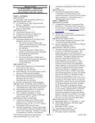
This is the GE <strong>AL</strong>-<strong>1810</strong> 4-Way Relay Card <strong>Installation</strong> <strong>Instructions</strong>.<br />
The relay card provides four single-pole double-throw<br />
(SPDT) relays with connection terminals to the common (C),<br />
normally open (N/O), and normally closed (N/C) contact.<br />
The relay contacts are rated 1 amp at 0 to 30 VDC. You can only<br />
install one <strong>AL</strong>-<strong>1810</strong> relay card per control panel or DGP with a<br />
maximum of four useable relays.<br />
Note: Clocked relay/open collector cards and 4-way relay cards<br />
can not be used together on the same device.<br />
An LED is provided for every relay to indicate activation<br />
(Figure 1).<br />
<strong>Installation</strong><br />
To install the relay card, do the following:<br />
1. Slide the terminal blocks together (Figure 2).<br />
Figure 2.<br />
Terminal block assembly<br />
Figure 1.<br />
Relay card components<br />
Mounting<br />
holes<br />
In<br />
connector<br />
Out<br />
connector<br />
J3<br />
J1<br />
- + - + - + - +<br />
RLY4 4 3 RLY3 RLY2 2 1 RLY1<br />
LED 4<br />
LED 3<br />
LED 2<br />
LED1<br />
J2<br />
NO C NC NO C NC NO C NC NO C NC<br />
Mounting<br />
holes<br />
Relay 4<br />
Relay 3<br />
Relay 2<br />
Relay 1<br />
2. Slide the terminal blocks over the pins on the relay card<br />
(Figure 3).<br />
Figure 3.<br />
CAUTION:<br />
You must be free of static electricity<br />
before handling circuit boards. Wear a<br />
grounding strap or touch a bare metal<br />
surface to discharge static electricity.<br />
Terminal block installation<br />
Terminal block<br />
assembly<br />
Relay jumper<br />
Mounting<br />
holes<br />
Mounting<br />
holes<br />
Interface cable<br />
to panel or DGP<br />
The card ships with the following hardware:<br />
• Four 3-position terminal blocks<br />
• Four clip-in standoffs<br />
• Four mounting screws<br />
• Four contact programming jumpers<br />
• One interface cable<br />
In connector<br />
Out connector<br />
3. Slide the relay contact programming jumpers over the pins<br />
on the relay card (Figure 3) for the required programming.<br />
Jumper removed or placed on center pin only. Dry<br />
contact.<br />
Jumper on center pin and plus pin. Supplies AUX plus<br />
to the common terminal of the relay.<br />
Jumper on center pin and minus pin. Supplies AUX<br />
minus to the common terminal of the relay.<br />
4. Mount the relay card in the control panel or DGP enclosure<br />
using the four clip-in standoffs and the mounting screws.<br />
5. Remove power from the system. Plug the interface cable<br />
into the control panel or DGP and into the In Connector on<br />
the relay card (Figure 3).<br />
Note: If you use the Out Connector to plug an <strong>AL</strong>-<strong>1810</strong> into<br />
another <strong>AL</strong>-<strong>1810</strong>, relays on the second card will follow<br />
relays on the first.<br />
6. Restore power to the system.
2<br />
<strong>AL</strong>-<strong>1810</strong> 4-Way Relay Card<br />
<strong>Installation</strong> <strong>Instructions</strong><br />
Specifications<br />
Supply voltage<br />
Current consumption<br />
Standby<br />
All relays active<br />
Contact ratings<br />
Dimensions<br />
Operating temperature<br />
Humidity<br />
Listing<br />
9 to 14 VDC<br />
-<br />
75 mA max.<br />
1 A at 0 to 30 VDC<br />
3.1 x 2 in. (80 x 52 mm)<br />
32 to 122°F (0 to 50°C)<br />
95% noncondensing<br />
UL 294 Standard for Access Control System<br />
Units<br />
UL 365 Standard for Police Station<br />
Connected Burglar Alarm Units and Systems<br />
UL 609 Standard for Local Burglar Alarm<br />
Units and Systems<br />
UL 1610 Standard for Central Station Burglar-<br />
Alarm Units<br />
UL 1635 Standard for Digital Alarm Communicator<br />
Systems Units<br />
Technical support<br />
Toll-free: 888.GESECURity (888.437.3287 in the US, including Alaska and Hawaii; Puerto Rico; Canada).<br />
Outside the toll-free area: Contact your local dealer.<br />
www.gesecurity.com