
Create successful ePaper yourself
Turn your PDF publications into a flip-book with our unique Google optimized e-Paper software.
R<br />
Kobalt & K Design ® is a registered<br />
trademark of LF, LLC. All rights reserved.<br />
R<br />
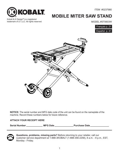
ITEM #0237980<br />
MOBILE MITER SAW STAND<br />
MODEL #ST0603W<br />
Français p. 21<br />
Español p. 41<br />
NOTICE: The serial number and MFG date code of the unit can be found on the nameplate of the<br />
machine. Record these numbers below for future reference.<br />
ATTACH YOUR RECEIPT HERE<br />
Serial Number MFG Date Purchase Date<br />
Questions, problems, missing parts Before returning to your retailer, call our<br />
customer service department at 1-888-3KOBALT (1-888-356-2258), 8 a.m. - 8 p.m., EST,<br />
Monday - Friday.<br />
1
TABLE OF CONTENTS<br />
Product Specifications ..................................................................................................................... 2<br />
Package Contents............................................................................................................................ 2<br />
Hardware Contents.......................................................................................................................... 4<br />
Safety Information............................................................................................................................ 5<br />
Knowing the Stand........................................................................................................................... 6<br />
Preparation....................................................................................................................................... 7<br />
Assembly Instructions....................................................................................................................... 8<br />
Adjustment Instructions.................................................................................................................... 10<br />
Operating Instructions...................................................................................................................... 11<br />
Replacement Parts List and Exploded View.................................................................................... 17<br />
Warranty........................................................................................................................................... 20<br />
PRODUCT SPECIFICATIONS<br />
Stand height with mounting brackets<br />
Work table size<br />
Size of the folded <strong>stand</strong><br />
Size of the extended <strong>stand</strong><br />
Diameter of wheel<br />
Maximum weight load<br />
32 in.<br />
18 in. x 36 in.<br />
46 in. (L) x 25.4 in. (W) x 14.5 in. (H)<br />
52.7 in. (L) x 25.4 in. (W) x 36 in. (H)<br />
8 in.<br />
300 lbs. (136.08 kg)<br />
PACKAGE CONTENTS<br />
UNPACKING YOUR STAND<br />
This product requires assembly.<br />
1. Remove the <strong>stand</strong> and all parts from the carton.<br />
2. Place the <strong>stand</strong> on the ground.<br />
3. Separate all parts from the packing material. Check each one with the illustration on page 3 to<br />
make certain all items are accounted for before discarding any packing material.<br />
WARNING: If any part is missing or damaged, do not attempt to assemble the <strong>stand</strong> until the<br />
missing or damaged part is correctly replaced.<br />
PART DESCRIPTION QUANTITY<br />
A Stand 1<br />
B Left <strong>stand</strong> leg 1<br />
C Front leg tube 1<br />
D Rear leg tube 1<br />
E Saw mounting brackets 2<br />
F Extension support assembly 2<br />
G Height adjustment knob 2<br />
H Wheel 2<br />
I Stand leg hardware bag 1<br />
J Wheel hardware bag 1<br />
K Securing hardware 4 sets<br />
2
PACKAGE CONTENTS<br />
A B C<br />
D<br />
E<br />
F G H<br />
I J K<br />
3
HARDWARE CONTENTS (not shown to actual size)<br />
BAG PART DESCRIPTION QUANTITY<br />
I AA M6*1.0-45 Screw 8<br />
BB φ6*18-1.5 Washer 8<br />
CC M6*1.0 Nut 8<br />
BAG PART DESCRIPTION QUANTITY<br />
J DD M10*1.5-115 Bolt 2<br />
EE φ10*20-3 Washer 6<br />
FF Sleeve 2<br />
GG M10*1.5 Nut 2<br />
BAG PART DESCRIPTION QUANTITY<br />
K HH M8*1.25-45 Bolt 4<br />
II φ8*16-2.5 Washer 4<br />
JJ M8*1.25 φ8*28-2.5 Washer 4<br />
KK M8*1.25 Nut 4<br />
AA BB CC DD EE FF<br />
GG HH II JJ KK<br />
4
SAFETY INFORMATION<br />
GENERAL SAFETY INFORMATION<br />
WARNING<br />
Read and under<strong>stand</strong> all warnings and operating instructions before using any tool or<br />
equipment. When using tools or equipment, basic safety precautions should always be<br />
followed to reduce the risk of personal injury. Improper operation, maintenance or modification<br />
of tools or equipment could result in serious injury and property damage. There are certain<br />
applications for which tools and equipment are designed. It is strongly recommended that this<br />
product NOT be modified and/or used for any application other than for which it was designed.<br />
WARNING<br />
● Failure to follow these rules may result in serious personal injury.<br />
● To reduce the risk of injury, keep both hands on handle when raising and lowering the <strong>stand</strong>.<br />
Please read and under<strong>stand</strong> this entire manual before attempting to assemble, operate or install the<br />
product. These safety instructions are not meant to cover every possible condition that could occur.<br />
● This product was designed to be used as a <strong>stand</strong> for <strong>miter</strong> <strong>saw</strong>s, scroll <strong>saw</strong>s, planers, benchtop<br />
sanders and grinders. The <strong>stand</strong> will support up to 300 lbs. (136.08 kg). Any misuse or abuse can<br />
result in product damage or personal injury.<br />
● Do not <strong>stand</strong> on the work table. It is unsafe to climb, sit or <strong>stand</strong> on the <strong>stand</strong>. Do not use the<br />
extension support arms as a ladder or scaffolding.<br />
● Properly secure the <strong>miter</strong> <strong>saw</strong>, scroll <strong>saw</strong>, planer, benchtop sander or grinder to the <strong>stand</strong> before<br />
operation. Follow the mounting instructions carefully. Fasten the tool to the <strong>saw</strong> mounting rails<br />
securely as instructed.<br />
● Place the product on a flat and level surface to prevent rocking or tipping.<br />
● Take care during the raising and lowering of the <strong>stand</strong> to reduce the hazard of pinching hands and<br />
fingers.<br />
● Check the legs and other supports to see that they are properly locked in place before operation.<br />
● Do not modify or use the <strong>stand</strong> for any operation for which it is not intended.<br />
● When hauling the <strong>stand</strong> in a vehicle, securely tie it down to prevent movement and possible damage.<br />
● ALWAYS use eye protection. All users and by<strong>stand</strong>ers must wear eye protection that conforms to<br />
ANSI Z87.1.<br />
● ALWAYS use safety glasses. Everyday eyeglasses are NOT safety glasses. Also use face or dust<br />
mask if cutting operation is dusty. ALWAYS WEAR CERTIFIED SAFETY EQUIPMENT:<br />
● ANSI Z87.1 eye protection (CAN/CSA Z94.3).<br />
● ANSI S12.6 (S3.19) hearing protection.<br />
● NIOSH/OSHA/MSHA respiratory protection.<br />
5
KNOWING THE STAND<br />
Left extension<br />
support assembly<br />
Work stop plate<br />
adjustment knob<br />
Back rail<br />
Right extension<br />
support assembly<br />
Locking button<br />
Cam latches<br />
LEFT<br />
FRONT<br />
Wheels<br />
Right <strong>stand</strong> leg<br />
Front leg tube<br />
RIGHT<br />
FRONT<br />
Rear leg tube<br />
Leveling foot<br />
Miter <strong>saw</strong> mounting brackets<br />
Storage tray<br />
Work support<br />
locking handles<br />
Handle<br />
RIGHT<br />
REAR<br />
Height adjustment knob<br />
of extension support<br />
Power cord<br />
hooks<br />
LEFT<br />
REAR<br />
Locking levers<br />
Locking hook<br />
6
PREPARATION<br />
Before beginning assembly or operation of the product, make sure all parts are present. Compare<br />
parts with package contents list and hardware contents list. If any part is missing or damaged, do not<br />
attempt to assemble, install or operate the product.<br />
Estimated Assembly Time: 15~20 minutes<br />
Tools required for assembly (not included): Adjustable Wrench, 10 mm Wrench, 13 mm Wrench,<br />
17 mm Wrench, Phillips Screwdriver.<br />
7
ASSEMBLY INSTRUCTIONS<br />
ASSEMBLING THE RIGHT FRONT AND REAR<br />
LEG TUBES (FIG. 1)<br />
● Unpack all parts and group them together by type<br />
and size. Refer to the parts list in order to verify<br />
the correct quantities.<br />
● Insert the front leg tube (C) with the leveling foot<br />
(1) in the right <strong>stand</strong> leg (2) using two bolts (AA),<br />
two washers (BB) and two nuts (CC).<br />
● Insert the rear leg tube (D) in the other side of the<br />
right <strong>stand</strong> leg (2) in the same manner.<br />
NOTE: The bent parts of the leg tubes (C, D)<br />
should point outward in opposite directions from<br />
each other.<br />
● Tighten using a 10 mm wrench for the nuts (CC)<br />
and a Phillips screwdriver for the bolts (AA).<br />
1<br />
2<br />
Front<br />
BB<br />
AA<br />
AA<br />
BB<br />
CC<br />
C<br />
1<br />
D<br />
CC<br />
ASSEMBLING THE STAND LEG (FIG. 2, 3)<br />
● Insert the left <strong>stand</strong> leg (B) in the other side of the<br />
<strong>stand</strong>. (Fig. 2)<br />
● Insert two screws (AA), two flat washers (BB) and<br />
two nuts (CC) on each side of the leg.<br />
● Attach one wheel (H) to the outer side of the <strong>stand</strong><br />
leg using the hex bolt (DD), the sleeve (FF), three<br />
flat washers (EE) and the nut (GG). (Fig. 3)<br />
NOTE: Verify that the side of the wheel that has<br />
the most ribs (3) is facing toward the <strong>stand</strong> as<br />
shown in the insert (Fig. 3).<br />
● Tighten using two 17 mm wrenches for the nut<br />
and bolt.<br />
NOTE: Do not overtighten. Doing so will not allow<br />
the wheels to turn.<br />
● Repeat the above steps for the other wheel.<br />
2<br />
Rear<br />
AA<br />
BB<br />
CC<br />
B<br />
3<br />
B<br />
FF<br />
EE<br />
EE<br />
GG<br />
3<br />
DD<br />
EE<br />
H<br />
8
ASSEMBLING THE EXTENSION SUPPORT<br />
ASSEMBLY (FIG. 4)<br />
● Insert an extension support assembly (F) in the<br />
right extension support arm (2) and secure by<br />
using a height adjustment knob (G).<br />
● Repeat on other side.<br />
4<br />
F<br />
2 G<br />
ASSEMBLING THE SAW MOUNTING BRACKETS<br />
(FIG. 5)<br />
● Press the locking button (1) and lift upward on the<br />
mounting bracket cam latch (2) so the rear holding<br />
clamp (3) is fully extended.<br />
● Place the rear holding clamp (3) on the back rail<br />
of the <strong>stand</strong>, and then lower the front end of the<br />
mounting bracket over the front rail of the <strong>stand</strong>.<br />
● Slide the mounting bracket to the desired position,<br />
and then push down the bracket cam latch (2) to<br />
lock.<br />
● Repeat the above steps for the other mounting<br />
bracket.<br />
5<br />
3<br />
Front<br />
2<br />
1<br />
POWER CORD HOOKS (FIG. 6)<br />
● Storage for the power cord is located on the ends<br />
of the <strong>saw</strong> mounting brackets (E). Wrap the power<br />
cord onto the hooks (1) when the <strong>saw</strong> is not in<br />
use. This can prevent damage to the power cord.<br />
6<br />
E<br />
1<br />
9
ADJUSTMENT INSTRUCTIONS<br />
ADJUSTING THE EXTENSION SUPPORTS (FIG. 7)<br />
The extension support assembly helps keep the<br />
workpiece level and stable during cutting operations.<br />
● Lift the cam locking handle (1) up and slide the<br />
extension support assembly to the desired length.<br />
Repeat for the other extension.<br />
● Press the locking handle (1) down to lock.<br />
● Loosen the height adjustment knob (G) to adjust<br />
the extension support assembly (F) to the desired<br />
height and then tighten the knob.<br />
● If repetitive cutting is required, loosen the plate<br />
adjustment knob (2) to adjust the work stop plate<br />
(3) to the desired height, and then tighten.<br />
ADJUSTING THE SAW MOUNTING BRACKETS<br />
(FIG. 8)<br />
If the <strong>saw</strong> mounting brackets can slide over the<br />
top rails or be removed from the top rails when the<br />
bracket locking cam latches (4) are locked, the bracket<br />
adjustment screws need to be tightened. If the <strong>saw</strong><br />
mounting brackets will not fit over the top rails, the<br />
bracket adjustment screws need to be loosened.<br />
NOTE: The <strong>saw</strong> should be removed from the<br />
mounting brackets before attempting to tighten or<br />
loosen the bracket adjustment screws (2).<br />
7<br />
2<br />
F<br />
8<br />
6<br />
G<br />
3<br />
1<br />
1<br />
2<br />
3<br />
4<br />
● Loosen the lock nut (1) using a 10 mm wrench.<br />
● Going through the hole (5) of the power cord<br />
clamp (6), use a Phillips screwdriver to turn the<br />
adjustment screw for the <strong>saw</strong> mounting bracket.<br />
5<br />
Turn the screw clockwise to tighten the bracket or<br />
counterclockwise to loosen it.<br />
NOTE: If the bracket locking cam latch of the <strong>saw</strong> mounting bracket cannot easily be pushed down<br />
into the lock position, the adjustment screw is too tight. Do not force the bracket locking cam latch<br />
into the lock position. Loosen the adjustment screw to adjust it.<br />
● Press the locking button (3) and lift up the bracket locking cam latch (4) so the rear holding clamp<br />
is fully extended.<br />
● Install the rear holding clamp on the back rail of the <strong>stand</strong>, then lower the front end of the <strong>saw</strong><br />
mounting bracket over the front rail of the <strong>stand</strong> to seat fully over the rails.<br />
● Lock the bracket into place and check to make sure there is no movement.<br />
● When the proper tension is achieved, tighten the lock nut (1) to secure.<br />
● Repeat the above steps for the <strong>saw</strong> mounting bracket.<br />
10
OPERATING INSTRUCTIONS<br />
SETTING UP THE STAND (FIG. 9, 10, 12)<br />
● Lift the <strong>stand</strong> to its upright position.<br />
● Unfold the right side leg (1) by releasing the<br />
locking levers (2) into slot B (middle slot), then<br />
rest the right side of the <strong>stand</strong> onto the floor.<br />
(Fig. 9, 10)<br />
WARNING: To properly lock the <strong>stand</strong> legs, the<br />
two locking levers (2) MUST be secured in the slot<br />
on the cover plate.<br />
● Release the locking hook (3) from the stop<br />
screw (8).<br />
● Hold the two handles (4) located on the left side of<br />
the <strong>stand</strong> and slowly lift the <strong>stand</strong> top upward to its<br />
highest position. The <strong>stand</strong> should lock into place<br />
securely. (Fig. 10)<br />
WARNING: DO NOT MOUNT ANY TOOL<br />
UNLESS THE STAND TOP IS SECURELY<br />
LOCKED.<br />
9<br />
2<br />
A<br />
B<br />
C<br />
1<br />
8<br />
3<br />
10<br />
4<br />
FOLDING THE STAND (FIG. 9, 11, 12)<br />
● Hold the two handles (4), step on the bottom<br />
left <strong>stand</strong> leg (6) and then lift up on the handles<br />
slightly. (Fig. 11)<br />
● Press in on the two locking levers (5), located<br />
under the handles, with your thumbs and slowly<br />
lower the <strong>stand</strong> top to its lowest position.<br />
● Rotate the locking hook (3) to the stop screw (8)<br />
and secure the legs of the <strong>stand</strong> into position.<br />
● Raise the right side of the <strong>stand</strong> to place the <strong>stand</strong><br />
in its upright position.<br />
● Fold the right <strong>stand</strong> leg (1) to the <strong>stand</strong> body by<br />
releasing the two locking levers (2) (Fig. 9) from<br />
slot B to either slot A (for storage) or slot C (for<br />
transport). When in transport mode, use the two<br />
legs as handles.<br />
NOTE: Also see the instructions on the <strong>stand</strong><br />
before operating.<br />
11<br />
3<br />
7<br />
8<br />
5<br />
6<br />
4<br />
11
12<br />
Setting up the <strong>stand</strong><br />
Transporting / folding the <strong>stand</strong><br />
transporting<br />
folding<br />
12
ATTACHING THE SAW TO THE MOUNTING<br />
BRACKETS (FIG. 13, 14)<br />
Always position the <strong>saw</strong> to achieve maximum<br />
balance and stability. All four corners of the <strong>saw</strong> must<br />
be bolted securely to the <strong>saw</strong> mounting brackets<br />
before use. Make sure bolts do not extend above the<br />
table of the <strong>saw</strong>.<br />
NOTE: Only four sets of securing hardware are<br />
provided with the <strong>stand</strong>. Each set includes a bolt, two<br />
washers and a nut. If the provided hardware does not<br />
work with your <strong>saw</strong>, use hardware that will properly<br />
secure your <strong>saw</strong>.<br />
13<br />
KK<br />
JJ<br />
WARNING: Ensure that the <strong>saw</strong> mounting<br />
brackets can be clamped securely on the <strong>stand</strong><br />
before mounting the <strong>saw</strong>.<br />
If the <strong>saw</strong> has mounting holes that line up with<br />
the slots in the <strong>saw</strong> mounting brackets:<br />
● Unplug the <strong>saw</strong> and lock the cutting head to its<br />
down position. Place the two mounting brackets<br />
onto a stable, flat surface.<br />
● Position the brackets to match the distance of the<br />
mounting holes on the <strong>saw</strong> base. Place the <strong>saw</strong><br />
onto each bracket.<br />
NOTE: If the <strong>saw</strong> is heavy/large, get someone’s<br />
assistance to position the brackets under the <strong>saw</strong>.<br />
NOTE: You can also place the <strong>saw</strong> onto two wood<br />
supports (1) (not included) and then position the<br />
mounting brackets under the <strong>saw</strong>.<br />
● Insert two bolts (HH) and two flat washers (II)<br />
under the bracket slot and into the two mounting<br />
holes on the left side of the <strong>saw</strong> base. Place a flat<br />
washer (JJ) and a nut (KK) onto each bolt.<br />
● Tighten using two 13 mm wrenches.<br />
NOTE: Do not overtighten the nuts until the <strong>saw</strong><br />
base is properly aligned on the brackets.<br />
● Repeat the above steps to attach the right side of<br />
the <strong>saw</strong> base to the other mounting bracket.<br />
● After checking that both mounting brackets are<br />
parallel to each other, tighten all four nuts to hold<br />
the <strong>saw</strong> in position.<br />
14<br />
II<br />
HH<br />
6<br />
2<br />
4<br />
5<br />
7<br />
FRONT<br />
3<br />
FRONT<br />
2<br />
1<br />
1<br />
If the <strong>saw</strong> has holes that do not line up with the<br />
slots on the <strong>saw</strong> mounting brackets:<br />
● Unplug the <strong>saw</strong> and lock the cutting head to its<br />
down position.<br />
● Mount the <strong>saw</strong> onto a wood board (1) at least<br />
1/2 in. thick (not included).<br />
13
● Mark the four mounting holes from the <strong>saw</strong> base<br />
onto the wood board using a pencil or pen (not<br />
included). Take the <strong>saw</strong> off the board.<br />
● Drill 1/4 in. diameter holes through the board at<br />
each location.<br />
● Turn the board over and place the two mounting<br />
brackets on the board. The brackets should be<br />
placed outside of the four holes just drilled. Mark<br />
four points through the slots, two on each bracket,<br />
using a pencil or pen, then remove the brackets.<br />
● Drill 1/4 in. diameter holes through the board at<br />
each marked location.<br />
● Mount the two <strong>saw</strong> brackets to the board using<br />
the four drilled holes and four bolts, eight washers<br />
and four nuts.<br />
NOTE: Hardware for this is NOT provided with<br />
the <strong>saw</strong>.<br />
● Turn the board over and mount the <strong>saw</strong> to the<br />
four drilled holes using the provided securing<br />
hardware.<br />
● Tighten all bolts and nuts before mounting the<br />
<strong>saw</strong> assembly to the <strong>stand</strong>.<br />
15<br />
1<br />
2<br />
3<br />
MOUNTING THE SAW TO THE STAND (FIG. 15)<br />
WARNING: Do not mount the <strong>saw</strong> to the <strong>stand</strong><br />
without first ensuring the <strong>stand</strong> is extended fully and<br />
locked securely. Failure to do so may result in possible<br />
injury and damage to the <strong>stand</strong> and the <strong>saw</strong>.<br />
● Make sure the lock handles (1) of the <strong>saw</strong><br />
mounting brackets (2) are in the unlocked position.<br />
● Lift the rear end of the <strong>saw</strong> assembly (the <strong>saw</strong><br />
on the mounting brackets) onto the back rail. The<br />
rear holding clamps on the <strong>saw</strong> mounting brackets<br />
(2) must seat fully onto the back rail.<br />
● Lower the front end of the <strong>saw</strong> assembly onto the<br />
front rail. The front holding clamps on the <strong>saw</strong><br />
mounting brackets must seat fully on the front rail.<br />
● Lock the brackets in position by pressing down on<br />
the two locking cam latches (1).<br />
● Check the position of the assembly on the <strong>stand</strong><br />
and adjust if needed.<br />
NOTE: Make sure the weight of the <strong>saw</strong> assembly<br />
is evenly distributed over the rails.<br />
14
MOUNTING OTHER MACHINES TO THE STAND<br />
This <strong>stand</strong> was designed to be used for <strong>miter</strong> <strong>saw</strong>s. However, other tools such as scroll <strong>saw</strong>s,<br />
planers, benchtop sanders and grinders can be mounted if needed. The following drawings show how<br />
to position the machine on the top of the <strong>stand</strong>.<br />
NOTE: NOT FOR USE WITH TABLE SAWS.<br />
Scroll Saw<br />
Scroll Saw<br />
15
Planer<br />
Planer<br />
(holes: 13" x 18")<br />
(material movement)<br />
Sander<br />
Typical Grinder<br />
16
REPLACEMENT PARTS LIST<br />
I.D. Description Size Q’ty I.D. Description Size Q’ty<br />
0J5G FLAT WASHER φ8*18-1.5 6 39RP 8 IN. WHEEL 2<br />
0JS8 HEX. HD. BOLT M10*1.5-115 2 39S2 CAP HD. SQ. NECK BOLT M8*1.25-65 2<br />
0K4Q CR. RE. TRUSS HD. SCREW M6*1.0-15 1 39V5 END CAP 2<br />
0KBR CR. RE. PAN HD. TAPPING M3.5*20-8 2 39V7 END CAP 1<br />
SCREW<br />
39V8 END CAP 2<br />
2CA8 CR. RE. TRUSS HD. ROUND M6*1.0-12 1 39VL PLUNGER HANDLE 2<br />
NECK SCREW<br />
39WQ MOUNTING BRACKET<br />
1<br />
2FTA END CAP 4 (LEFT)<br />
2HDS WING NUT M8*1.25-2B 1 39WR MOUNTING BRACKET<br />
1<br />
2JQD LEVELING FOOT 1 (RIGHT)<br />
2WVF COMPRESSION SPRING 2 39WY CONNECTOR TUBE<br />
2<br />
2XGE SLEEVE 2 ASSEMBLY<br />
32A0 BRACKET STOP 2 39WZ CAP HD. SQ. NECK BOLT M8*1.25-60 2<br />
32AF SPRING 2 39X0 LOCKING HANDLE<br />
2<br />
32R9 NUT CHUCK M5*0.8 T=5 4 ASSEMBLY<br />
32RA NUT CHUCK M6*1.0 T=6 12 39X1 CAP HD. SQ. NECK BOLT M8*1.25-55 2<br />
32RB NUT CHUCK M8*1.25 T=8 8 39X2 CAP HD. SQ. NECK BOLT M8*1.25-50 2<br />
32RE FLAT WASHER φ6*18-1.5 8 39XD COMPRESSION SPRING 2<br />
32RN E-RING 2 39ZQ OPERATOR’S MANUAL 1<br />
32UG CR. RE. TRUSS HD. ROUND M5*0.8-15 2 3A0A TRADEMARK LABEL 4<br />
NECK SCREW<br />
3A0B ASSEMBLY LABEL 1<br />
37TB FLAT WASHER φ6*13-1 2 3A0D WARNING LABEL 1<br />
37TC FLAT WASHER φ8*16-2.5 6 3A0L CAUTION LABEL 1<br />
396J BOLT 2 3A0M CAUTION LABEL 1<br />
396N HANDLE 1 3A0N CAUTION LABEL 2<br />
396R POWER CORD HOOK (RIGHT) 1 3A0Q WARNING LABEL 1<br />
396U LOCK HANDLE 1 3A0T WARNING LABEL 2<br />
396X STORAGE TRAY 1 3A0U WARNING LABEL 1<br />
3975 SUPPORTING TUBE ASSEMBLY 1 3A0V STICKER 1<br />
3976 RIGHT LEG SUPPORT 1 3ADN HEX. SOC. HD. CAP BOLT M6*1.0-20 2<br />
397D EXTENSION WING BRACKET<br />
2 3ADP HEX. SOC. HD. CAP BOLT M5*0.8-16 2<br />
ASSEMBLY<br />
3ADQ CR. RE. PAN HD. ROUND M6*1.0-14 2<br />
397F LOCKING HOOK 1 NECK SCREW<br />
397L UPPER TUBE ASSEMBLY 2 3ADS HEX. NUT M6*1.0 T=5 1<br />
397Q RIGHT BRACKET ASSEMBLY 1 3ADU CR. RE. PAN HD. SCREW M6*1.0-16 4<br />
3986 WORK STOP PLATE 2 3ADW CR. RE. TRUSS HD. SCREW M6*1.0-45 8<br />
398M HANDLE 2 3ADX HEX. HD. BOLT M8*1.25-45 4<br />
398N STOPPER 2 3ADZ NUT CHUCK M10*1.5 T=10 2<br />
398P LEVELING PAD 1 3AE0 SERRATED TOOTHED HEX. M8*1.25 T=7.5 4<br />
398R PLASTIC SLEEVE 2 FLANGE NUT<br />
399F LEG ASSEMBLY 1 3AE1 FLAT WASHER φ8*28-2.5 4<br />
399J BRACKET 2 3AE3 FLAT WASHER φ10*20-3 6<br />
399K STIFFENER 1 3AE4 FLAT WASHER φ6.3*15-4 1<br />
39C2 HANDLE 2 3B0S CR. RE. TRUSS HD. SCREW M5*0.8-8 2<br />
39CM POWER CORD HOOK (LEFT) 1 3B94 HANDLE 2<br />
39F3 BUSH 2<br />
17
EXPLODED VIEW<br />
3986<br />
398M<br />
3B94<br />
3A0A<br />
2JQD 2HDS 399J 2<br />
32RE 4<br />
39V7<br />
2 37TB<br />
39X0 2<br />
2<br />
3986<br />
397D 2<br />
3ADP 2<br />
2FTA 4<br />
32AF 2 32R9<br />
2<br />
39C2<br />
2<br />
2<br />
3ADU<br />
39WQ<br />
4<br />
32UG 2<br />
3ADS<br />
39WY2 32RB 4<br />
2 39RP 2<br />
39F3<br />
2<br />
3ADN<br />
37TC 2 3ADZ 2<br />
2<br />
3B0S 396X<br />
32RN 2<br />
396N<br />
3B94<br />
39XD 2<br />
396J 2<br />
32R9 2<br />
3A0M 3A0T<br />
32RA<br />
2 39V5 2<br />
397L 399F<br />
3A0A<br />
32A0 2 39WZ 2 3A0N<br />
397Q<br />
3A0U<br />
3A0A<br />
0K4Q<br />
3A0T<br />
396U<br />
3A0Q 3A0D<br />
3A0V<br />
399K<br />
3A0L<br />
39X2 2<br />
0J5G<br />
4<br />
2<br />
3A0B<br />
39V8 2<br />
3ADQ 39S2 39X1<br />
2<br />
0J5G 2 32RE 4<br />
3ADW 4<br />
32RA 4<br />
3AE3<br />
6<br />
398N 2<br />
0KBR 2<br />
39VL 2<br />
3975<br />
397F<br />
2XGE 2<br />
2WVF<br />
2<br />
398R 2 3AE4 2CA8<br />
39WR<br />
0JS8 2<br />
32RA 2<br />
3A0N<br />
32RA 4<br />
3976<br />
3ADW 4<br />
3ADX 4<br />
32RB 4<br />
39ZQ<br />
3A0A<br />
396R<br />
3AE1 4<br />
37TC 4<br />
3AE0<br />
398P<br />
4<br />
398M<br />
39CM<br />
18
WARNING LABEL REPLACEMENT<br />
If your warning labels become illegible or are missing, call 1-888-356-2258 for a free replacement.<br />
3A0Q<br />
3A0D<br />
3A0U<br />
3A0T<br />
3A0V<br />
19
WARRANTY<br />
The manufacturer will offer replacement parts for this product which under normal usage have<br />
proven to be defective in their manufacture or workmanship for a period of THREE (3) years from<br />
the date of initial retail purchase. This warranty is valid only to the original purchaser. This warranty<br />
is not transferable and does not cover any parts that have been subjected to misuse, abuse,<br />
alteration, overload, accident or normal wear of moving parts. Tools that have been sold<br />
“as is,” sold reconditioned or used as rental equipment are not covered.<br />
Warranty replacement parts can be obtained by contacting the manufacturer at 1-888-3KOBALT.<br />
Only the manufacturer is authorized to perform warranty service on this product. This warranty<br />
does not apply to accessories or damage caused where repairs have been made or attempted<br />
by others.<br />
The manufacturer is not responsible for direct, indirect, incidental or consequential damages.<br />
Some states do not allow limitations on how long an implied warranty lasts and/or do not allow the<br />
exclusion or limitation of incidental damages, so the above limitations may not apply to you. This<br />
warranty gives you specific legal rights, and you may also have other rights, which vary from state<br />
to state.<br />
The manufacturer makes no warranties, representations or promises as to the quality of its power<br />
tools other than those specially stated in this warranty.<br />
WARRANTY VOID IF PRODUCT USED FOR COMMERICAL PURPOSES.<br />
For replacement parts, call our customer service department at 1-888-3KOBALT (1-888-356-2258).<br />
20<br />
Printed in China