


You also want an ePaper? Increase the reach of your titles
YUMPU automatically turns print PDFs into web optimized ePapers that Google loves.
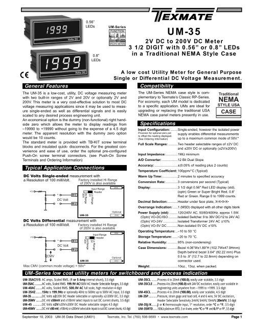
0.56”<br />
LEDs<br />
0.8”<br />
LEDs<br />
<strong>UM</strong>-Series<br />
<strong>UM</strong>-<strong>35</strong><br />
2V DC to 200V DC Meter<br />
3 1/2 DIGIT with 0.56” or 0.8” LEDs<br />
in a Traditional NEMA Style Case<br />
General Features<br />
The <strong>UM</strong>-<strong>35</strong> is a low-cost, utility, DC voltage measuring meter<br />
with two built-in ranges of 2V and 20V or optionally 2V and<br />
200V. This meter is a very cost-effective solution to most DC<br />
voltage measuring applications since it may be used to measure<br />
single-ended as well as differential signals and is easily<br />
scaled to any desired process engineering unit.<br />
An economical option is the dummy (non-functional) right handside<br />
zero which allows the meter to display readings from<br />
–19990 to +19990 without going to the expense of a 4.5 digit<br />
meter. The apparent resolution with the dummy zero option<br />
would be 10 counts.<br />
The standard meter is provided with TB-KIT screw terminal<br />
blocks and insulated quick- disconnects. For the greatest convenience<br />
and ease of use, order the optional pre-configured<br />
Push-On screw terminal connectors. (see Push-On Screw<br />
Terminals and Ordering Information)<br />
Typical Application Connections<br />
DC Volts Single-ended measurement with<br />
a Resolution of 100 milliVolt. Factory installed Hi Range<br />
of 200V is also available<br />
+V<br />
DC Volt<br />
DC Volts Differential measurement with<br />
a Resolution of 100 milliVolt. Factory installed Hi Range<br />
of 200V is also available<br />
+V<br />
CMV<br />
+<br />
DC Volt<br />
_<br />
Hi Range<br />
20V<br />
<strong>UM</strong>-<strong>35</strong><br />
Hi Range<br />
20V<br />
<strong>UM</strong>-<strong>35</strong><br />
Max CMV (common mode voltage) = 50V*<br />
+<br />
_<br />
SIG<br />
HI<br />
SIG<br />
LO<br />
SIG<br />
HI<br />
SIG<br />
LO<br />
Input Range<br />
Header<br />
Lo Range<br />
2V<br />
Input Range<br />
Header<br />
Lo Range<br />
2V<br />
Compatibility<br />
Specifications<br />
<strong>UM</strong>-Series low cost utility meters for switchboard and process indication<br />
<strong>UM</strong>-<strong>35</strong>ACI1/5 AC amps, Scaled RMS, (1 or 5 Amp internal shunt), 3.5 digit<br />
<strong>UM</strong>-<strong>35</strong>AC..............AC volts, Scaled RMS. 199.9V AC/500V AC Header Selectable Ranges, 3.5 digit<br />
<strong>UM</strong>-40AC ........AC volts, Scaled RMS. 500.0V AC full scale, high resolution 4 digit<br />
<strong>UM</strong>-<strong>35</strong>HZ ........15Hz to 199.9Hz or optionally 40Hz to 500Hz up to 500V AC input, 3.5 digit<br />
<strong>UM</strong>-<strong>35</strong> ..................DC Volts ±2/20V DC Header selectable or optionally ±2/200V DC, 3.5 digit<br />
<strong>UM</strong>-<strong>35</strong>MV ..........DC mV ±50mV and ±100mV select inputs to suit DC current shunts, 3.5 digit<br />
<strong>UM</strong>-45 ............DC Volts ±2V/±20V/±200V DC Header selectable ranges 4.5 digit<br />
<strong>UM</strong>-45MV ..........DC mV ±50 mV, ±100mV, or ±200mV selectable inputs to suit DC current shunts, 4.5 digit<br />
A low cost Utility Meter for General Purpose<br />
Single or Differential DC Voltage Measurement.<br />
SPAN<br />
Optional<br />
ZERO<br />
SPAN<br />
Optional<br />
ZERO<br />
The <strong>UM</strong>-Series NEMA case style is complementary<br />
to Texmate’s Classic RP-Series.<br />
For economy, each <strong>UM</strong> model is dedicated<br />
to a specific application. <strong>UM</strong>s are ideal for<br />
upgrading or replacing the traditional USA<br />
NEMA case panel meters presently in use.<br />
Traditional<br />
NEMA<br />
STYLE USA<br />
CASE<br />
Input Configuration: ........Single-ended, however the isolated power<br />
Provision for optional zero pot supply enables differential measurements<br />
to offset the reading displayed.<br />
(See Ordering Information) up to a maximum common mode of 50V.*<br />
Full Scale Ranges: ..........Two header selectable ranges of ±2V DC<br />
and ±20V DC or optionally (±2V/±200V)<br />
Input Impedance:.............1MΩ minimum<br />
A/D Converter: .................12 Bit Dual Slope<br />
Accuracy: .........................±(0.05% of reading plus 2 counts)<br />
Temperature Coefficient: 100ppm/°C (Typical)<br />
Warm Up Time:.................2 minutes to specified accuracy<br />
Conversion Rate: .............3 conversions per second (Typical)<br />
Display:.............................3 1/2 digit 0.56" Red LED display (std),<br />
(optn) Green or Super Bright Red, 0.8”<br />
Red or Green. Range 0 to 1999 counts.<br />
Decimal Selection:...........Header under face plate, X•X•X•X•<br />
Overrange Indication: .....1 (MSD) displayed with all other digits blank<br />
Power Supply (std):.........120/240V AC, 50/60/400Hz. approx 1.5W.<br />
(Optn) VO-DC/ISO ..........Isolated Switcher. 9 to 36V DC/12 to 24V AC<br />
(Optn) VO-24V ................Isolated Transformer 24V AC ±10%<br />
(Optn) VO-5V DC............Non-isolated 5V DC ±10%<br />
Operating Temperature: ..–10 to 50 °C<br />
Storage Temperature:......–20 to 70 °C.<br />
Relative Humidity: ...........95% (non-condensing)<br />
Case Dimensions: ...........Bezel 4.06”Wx1.89”H (102.7Wx47.9Hmm)<br />
Depth behind bezel 3.64" (92.22 mm) Plus<br />
0.5 to .9” (12.7 to 22.8mm) depending on<br />
connector used.<br />
Weight:..............................10oz., 13oz. when packed.<br />
<strong>UM</strong>-<strong>35</strong>CL ........Process 4 to 20mA (100.0), easily user scalable, 3.5 digit<br />
<strong>UM</strong>-<strong>35</strong>CLE ......Process 4 to 20mA (100.0) with 24V DC excitation, easily user scalable in<br />
engineering units anywhere from –1999 to +1999. 3.5 digit<br />
<strong>UM</strong>-45CL ........Process 4 to 20mA (100.00), easily user scalable, 4.5 digit<br />
<strong>UM</strong>-<strong>35</strong>P............Pressure, strain gage and load cell, 4 and 6 wire, 5V DC excitation,<br />
Header Selectable Sensitivity 2mV/V, 5mV/V, 10mV/V, 20mV/V, 3.5 digit<br />
<strong>UM</strong>-<strong>35</strong>J/K........J or K thermocouple input, 1° resolution, order °C or °F, 3.5 digit<br />
<strong>UM</strong>-<strong>35</strong>RTD......100Ω platinum RTD, 3 or 4 wire, order °C or °F and 0.1° or 1°, 3.5 digit<br />
September 10, 2003 <strong>UM</strong>-<strong>35</strong> <strong>Data</strong> <strong>Sheet</strong> (<strong>UM</strong>01) Texmate, <strong>Inc</strong>. Tel. (760) 598-9899 • www.texmate.com Page 1
Functional Diagram<br />
Test<br />
Common<br />
Hold<br />
120V<br />
Cut loop to turn OFF last digit for 199 display<br />
Optional<br />
Zero Pot<br />
Input HI<br />
Input LO<br />
AC Neutral<br />
240V<br />
AC Line<br />
Optional<br />
Zero Pot<br />
0.56" Display<br />
0.8" Optional Display<br />
Span Pot<br />
Span Pot<br />
J5<br />
TST H/T HLD SIG<br />
SIG<br />
HI<br />
LO<br />
AC1<br />
AC2<br />
AC3<br />
AC4<br />
GND<br />
47K<br />
1M<br />
110K<br />
GND<br />
1.XXX<br />
1X.XX<br />
1XX.X<br />
1XXX.<br />
Input Range<br />
Header<br />
Low Range<br />
(2V)<br />
Hi Range<br />
(20V or 200V)<br />
Connector Pinouts<br />
Decimal<br />
Select<br />
Header<br />
J4<br />
1M<br />
Span<br />
Pot<br />
Rectifier<br />
and<br />
Regulator<br />
Circuit<br />
+5 V DC<br />
GND<br />
-5 V DC<br />
470K<br />
0.22µF<br />
+ 5 V – 5 V<br />
Optional<br />
Zero<br />
Pot<br />
Input LO<br />
50K<br />
1M<br />
Input HI<br />
<strong>UM</strong>-Series are connectable using the TB-KIT screw terminal<br />
blocks provided with the meter. For greatest convenience, order<br />
a Texmate Push-On screw terminal connector. Alternatively, a<br />
pcb edge connector can be used.(see connector options)<br />
+ 5 V<br />
+ 1.25V<br />
J1<br />
J3<br />
– 5 V<br />
GND<br />
J2<br />
Input<br />
Protection<br />
Circuit<br />
Decimal Select Header<br />
Hold<br />
Test<br />
1.XXX<br />
1X.XX<br />
1XX.X<br />
1XXX.<br />
12 Bit<br />
Dual Slope<br />
A to D and<br />
Display Driver<br />
To Display<br />
Pins 11 & M - AC1 - Live AC Power Input:<br />
Pins 12 & N - AC2 - 110/220V AC Power Select:<br />
Pins 13 & P - AC3 - 110/220V AC Power Select:<br />
Pins 14 & R - AC4 - Neutral AC Power Input:<br />
TB-KIT<br />
Screw<br />
Terminals<br />
PCB Edge<br />
Connector<br />
AC1 & 2 Joined<br />
Component Layout<br />
J5<br />
Input High +<br />
DC Volts<br />
Input Low –<br />
AC Neutral<br />
100 to 120V AC<br />
A A B A C A D A E<br />
C C C C<br />
1 2 3 4<br />
10 11 12 13 14 15<br />
L M N P R S<br />
AC2 & 3 Joined<br />
200 to 240V AC &<br />
Optional 24V<br />
A A B A C A D A E<br />
C C C C<br />
1 2 3 4<br />
AC2 & 3<br />
Joined<br />
10 11 12 13 14 15<br />
L M N P R S<br />
Input Range<br />
header<br />
See below for<br />
connections<br />
Optional VO-DISO<br />
9-26V DC/12-24V AC<br />
A A B A C A D A E<br />
C C C C<br />
1 2 3 4<br />
N/C<br />
10 11 12 13 14 15<br />
L M N P R S<br />
Span Adjust<br />
Potentiometer<br />
J5<br />
Rear View of Meter<br />
PCB<br />
1 2 3 4 5 6 7 8 9 10 11 12 13 14 15<br />
120V<br />
240V<br />
AC Line<br />
!<br />
A<br />
B C D E F H J K L M N P R S<br />
Component Side Solder Side<br />
J5<br />
DISPLAY<br />
TEST<br />
HOLD/TEST<br />
COMMON<br />
SIGNAL<br />
INPUT<br />
HIGH<br />
SIGNAL<br />
INPUT<br />
LOW<br />
1<br />
2<br />
3<br />
4<br />
6<br />
7<br />
8<br />
9<br />
AC1 – 11<br />
AC2 – 12<br />
AC3 – 13<br />
AC4 – 14<br />
TST<br />
H/T<br />
I/P<br />
HI<br />
I/P<br />
LO<br />
A<br />
B<br />
C<br />
D<br />
E<br />
HLD<br />
H/T<br />
I/P<br />
HI<br />
I/P<br />
LO<br />
A<br />
B<br />
C<br />
D<br />
E<br />
A<br />
B<br />
C<br />
D<br />
F<br />
H<br />
J<br />
K<br />
HOLD<br />
HOLD/TEST<br />
COMMON<br />
SIGNAL<br />
INPUT<br />
HIGH<br />
SIGNAL<br />
INPUT<br />
LOW<br />
M – AC1<br />
N – AC2<br />
P – AC3<br />
R – AC4<br />
WARNING: AC and DC input signals and power supply<br />
voltages can be hazardous. Do Not connect live wires to<br />
screw terminal plugs, and do not insert, remove or handle<br />
screw terminal plugs with live wires connected.<br />
Pins 1 & 2 - Display Test: All numeric display segments will light<br />
up when this pin is connected to the H/T Common Pin. A Texmate<br />
TB-KIT Screw Terminal Clip can be used to access the Display<br />
Test function.<br />
Pins 3, 4, C & D - H/T Common Pin: The Hold and Display<br />
Test pins have to be connected to this pin to activate their<br />
respective functions.<br />
Pins A & B - Hold Reading: When this pin is connected to the<br />
H/T Common pin, A/D conversions will continue, but the display<br />
will not be updated until Pins A and B are disconnected from<br />
the H/T Common pin. When using a Texmate TB-KIT Screw<br />
Terminal, J5 has to be opened to disconnect the Test function<br />
and enable the Hold function. If both hold and test functions<br />
need to be accessed, a Push-On Screw Terminal can be used.<br />
Pins 6, 7, F & H - Signal High Input: Signal high input for the<br />
meter. Full-scale ranges of 2V or 20V can be selected on the<br />
Range Select Header. (Optional range of 2V/200V is also<br />
available)<br />
Pins 8, 9, J & K - Signal Low Input: Signal low input of the A/D<br />
Converter.<br />
Signal Conditioning Components<br />
LO<br />
Range<br />
HI<br />
Range<br />
To the<br />
Right Front<br />
LO<br />
Range<br />
HI<br />
Range<br />
Turn Clockwise to<br />
<strong>Inc</strong>rease Reading<br />
To the<br />
Left Front<br />
Turn Clockwise to<br />
<strong>Inc</strong>rease Reading<br />
INPUT RANGE Header<br />
SPAN Potentiometer (Pot)<br />
Calibration Procedure<br />
Optional Zero<br />
Adjust Potentiometer<br />
Range values are marked on the PCB. Two positions<br />
are provided. After selecting a new range with the<br />
single jumper clip, recalibration is required.<br />
The 15 turn SPAN pot is always on the right side<br />
(as viewed from the front of the meter). Typical<br />
adjustment is 100% of the input signal range.<br />
ZERO Potentiometer (Pot)<br />
The Optional ZERO pot when installed is always<br />
to the left of the SPAN pot (as viewed from the<br />
front of the meter). Typically it enables the displayed<br />
reading to be offset ±1000 counts.<br />
1. Select the required full scale voltage range by repositioning the<br />
jumper clip on the Range Select Header. A range of<br />
2/20V DC or optionally 2/200V DC full scale may be selected.<br />
2. Apply an input of 0 volts. The meter will autozero and display<br />
0000. If the zero needs to be offset use the optional Zero<br />
Offset pot.<br />
3. Apply a known high input signal that is within the full scale<br />
voltage range selected.<br />
4. Adjust the Span Pot until the meter displays the required<br />
reading for the signal being applied.<br />
5. The <strong>UM</strong>-<strong>35</strong> is now calibrated and ready for use.<br />
(Whenever you select a new range, you must re-calibrate to<br />
meet the specified accuracy.)<br />
Page 2<br />
Texmate, <strong>Inc</strong>. Tel. (760) 598-9899 • www.texmate.com<br />
September 10, 2003 <strong>UM</strong>-<strong>35</strong> <strong>Data</strong> <strong>Sheet</strong> (<strong>UM</strong>01)
Decimal Point Selection<br />
Remove faceplate by inserting a screwdriver<br />
blade in the slot at the bottom center of the faceplate.<br />
Press blade in to release catch and gently<br />
pry face plate outward from the bottom. (see also<br />
Case Dimension drawing)<br />
Push-On Screw Terminals<br />
They provide the greatest convenience and ease of use<br />
Texmate’s exclusive optional Push-On Connectors combine an edge<br />
card connector and a 10 position screw terminal block. Push-On<br />
Connectors are ordered preconfigured for each specific power supply<br />
voltage and each optional power supply available for the <strong>UM</strong>-Series.<br />
1.XXX<br />
1X.XX<br />
1XX.X<br />
1XXX.<br />
Decimal<br />
Select<br />
Header<br />
Decimal selection is made on the front of the display<br />
board by moving the jumper clip to the<br />
desired position on the header.<br />
Pinouts are marked<br />
on Connector<br />
TB-Kit Screw Connectors<br />
Six Screw Terminals included Free with each <strong>UM</strong> Series meter<br />
2 TB-KITs<br />
included<br />
A TB-KIT consists of 3 insulated<br />
Quick Connects and 3 of Texmate’s<br />
patented individual screw terminal<br />
blocks which attach directly to PCB<br />
inputs. These provide a Quick<br />
Connect tab and screw clamp<br />
termination. When using the TB-KIT<br />
screw terminal blocks, it is possible to<br />
select between 120V AC and 240V AC power, the optional low voltage<br />
switching power supply or the 24V AC power supply by connecting the<br />
screw terminals as shown in the diagrams below.<br />
Optional PCB Edge Connector<br />
Connector can be<br />
securely attached<br />
to case with screws<br />
CN-PUSH/<strong>UM</strong> . . . . . . . . . . . . . . . . . . . . . . . . . . . . . . . . . . . .100/120V AC<br />
CN-PUSH/<strong>UM</strong>01 . . . . . . . . . . . . . . . . . . . . . . . . . . . . . . . . . 200/240V AC<br />
CN-PUSH/<strong>UM</strong>02 . . . . . . . . . . . . . . . . . . .Switch Selectable 120/240V AC<br />
CN-PUSH/<strong>UM</strong>03 . . . . . . . . . . . . . . . . . . . . . . . . . . . . . . . . . . . . . .24V AC<br />
CN-PUSH/<strong>UM</strong>04 . . . . . . . . . . . . . . . . . . . . . . . . . . .9-36V DC/12-24V AC<br />
CN-PUSH/<strong>UM</strong>05 . . . . . . . . . . . . . . . . . . . . . . . . . . . . . . . . . . . . . . .5V DC<br />
Pinout Change-Over Connectors<br />
To replace DPMs in existing panels where matching pinouts are<br />
required, Texmate can provide custom pinout Change-over<br />
Connectors, either with PCB gold finger terminations, (shown below)<br />
or customized versions of Push-On Screw Terminals. (shown above)<br />
Rear View of PCB Edge Connector<br />
1 2 3 4 5 6 7 8 9 10 11 12 13 14 15<br />
Selecting Power Supply Voltages<br />
With TB-KIT<br />
Screw Terminals<br />
PCB BOARD : COMPONENT SIDE<br />
A A B A C A D A E<br />
C<br />
1<br />
C<br />
2<br />
C<br />
3<br />
C<br />
4<br />
PCB BOARD : COMPONENT SIDE<br />
A A B A C A D A E<br />
C<br />
1<br />
C<br />
2<br />
C<br />
3<br />
C<br />
4<br />
Joins<br />
AC2 & 3<br />
PCB BOARD : COMPONENT SIDE<br />
A A B A C A D A E<br />
C<br />
1<br />
C<br />
2<br />
C<br />
3<br />
C<br />
4<br />
N/C<br />
A<br />
B C D E F H J K L M N P R S<br />
A standard 30 pin edge connector (two rows of 15 pins on<br />
0.156" centers) may also be used to connect the <strong>UM</strong>-Series.<br />
Order part no. CN-L15. For different power supply voltage connection<br />
details, see pin connections below.<br />
With Optional<br />
PCB Edge Connector<br />
For 100 to 120V AC, 50/60 Hz<br />
Join these pins<br />
11 12 13 14<br />
M N P R<br />
Top & bottom gold<br />
fingers are joined on PCB<br />
10 11 12 13 14 15<br />
L M N P R S<br />
For 200 to 240V AC, 50/60 Hz<br />
or For Optional 24V AC (P.N.:V0-24V)<br />
11 12 13 14<br />
M N P R<br />
Top & bottom gold<br />
fingers are joined on PCB<br />
10 11 12 13 14 15<br />
L M N P R S<br />
For Isolated 9-36V DC/12-24V AC, 50/60 Hz<br />
Switching Power Supply<br />
11 12 13 14<br />
Join these pins<br />
10 11 12 13 14 15<br />
M N P R<br />
L M N P R S<br />
Top & bottom gold<br />
fingers are joined on PCB<br />
Change-over Connector<br />
shown is for Analogic models<br />
AN25M02,AN25M03,<br />
AN25M04 and AN25M05.<br />
Face Plate Descriptors<br />
Volts AC<br />
Amps AC<br />
Volts DC<br />
Hz<br />
RPM<br />
Milliamps AC Milliamps DC ˚C<br />
Millivolts AC Millivolts DC ˚F<br />
Kilowatts<br />
kg/cm<br />
2<br />
Amps DC<br />
Watts<br />
%<br />
Kilovolts AC<br />
DCµA<br />
pH<br />
kWH kVAR Power Factor<br />
kΩ<br />
CosØ M/min<br />
3<br />
m /hr<br />
Custom Face Plates<br />
Ω<br />
psi<br />
Part Number<br />
CN-<strong>UM</strong>/ANLGC<br />
To customize the face plate, each<br />
<strong>UM</strong>-meter is supplied with a white<br />
printed clear adhesive label containing<br />
various popular descriptors.<br />
Choose the descriptor, peel off the<br />
adhesive backing and align the<br />
descriptor in the lower right corner<br />
of the standard face plate.<br />
Texmate Produces Thousands of<br />
Custom OEM Face Plates<br />
Have Texmate Design and produce a<br />
Custom Face Plate for your next project!<br />
• Custom face plates have a nonrecurring<br />
artwork charge. A serial<br />
number is then assigned to each<br />
artwork to facilitate reordering.<br />
• Small Run or One-Off custom face plates incur an installation<br />
charge, and are generally printed on a special plastic film, which is<br />
then laminated to custom faceplate blanks as required.<br />
• Large Run (250 pieces min): custom face plates are production<br />
silk screened, issued a part number, and held in stock for free<br />
installation as required by customer orders.<br />
• OEMs may also order Custom Meter Labels, Box Labels, Custom<br />
<strong>Data</strong> <strong>Sheet</strong>s and Instruction Manuals.<br />
September 10, 2003 <strong>UM</strong>-<strong>35</strong> <strong>Data</strong> <strong>Sheet</strong> (<strong>UM</strong>01)<br />
Texmate, <strong>Inc</strong>. Tel. (760) 598-9899 • www.texmate.com Page 3
<strong>UM</strong> Case Dimensions and Panel Cutouts<br />
This NEMA Case will fit any existing cutout<br />
with dimensions that are between the Snug<br />
and Loose Fitting dimensions shown below.<br />
3.84"<br />
(97.5mm)<br />
Loose Fitting<br />
0.1"<br />
(2.6mm) 4 places<br />
1.64"<br />
(41.6mm)<br />
Snug Fitting<br />
3.58"<br />
(91mm)<br />
3.7"<br />
(94mm)<br />
4 places 0.66"<br />
(16.7mm)<br />
2 places 0.38"<br />
(9.6mm)<br />
Panel Cutout for Front Panel Removal<br />
To enable removal of the panel meter<br />
from a mounting panel without requiring<br />
rear access, make the panel cutout as<br />
shown above, using the mounting plate<br />
supplied with the meter as a template.<br />
The mounting holes should then be<br />
1.89"<br />
(47.9mm)<br />
tapped to match the mounting screws. 1.89"<br />
(47.9mm)<br />
To remove the face plate,<br />
carefully insert screwdriver blade<br />
at bottom slot to release catch and<br />
gently pry outward to release the plate.<br />
For new installations see Optimum Panel Cutout<br />
or Panel Cutout for Front Panel Removal<br />
DIA = 0.125"<br />
(3.0 mm)<br />
2 holes<br />
1.78"<br />
(45mm)<br />
PCB<br />
Retaining<br />
Brackets<br />
3.6"<br />
(91.44mm)<br />
4.06"<br />
(102.7mm)<br />
0.3"<br />
(7.62mm)<br />
0.59"<br />
(15mm)<br />
3.34"<br />
(84.6mm)<br />
4.1"<br />
(104mm)<br />
2.05"<br />
(52mm)<br />
3.84"<br />
(97.5mm)<br />
4.21"<br />
(106.5mm)<br />
Threaded Holes<br />
3.7" (94mm)<br />
3.86"<br />
(98mm)<br />
0.17" 4 places<br />
(4.3mm)<br />
0.18" 4 places<br />
(4.5mm)<br />
FRONT VIEW<br />
4.06"<br />
(102.7mm)<br />
1.03"<br />
(26mm)<br />
Mounting<br />
Plate<br />
1.66"<br />
(41.9mm)<br />
Optimum Panel Cutout<br />
not requiring holes<br />
for mounting screws<br />
Ordering Information<br />
Standard Options for this Model Number<br />
Part Number Description List<br />
BASIC MODEL N<strong>UM</strong>BER <strong>Inc</strong>ludes 2 TB-KITs, standard display<br />
and standard power supply unless optional versions are ordered.<br />
<strong>UM</strong>-<strong>35</strong> . . . . .DPM, ±2/20V DC Header selectable or optionally ±2/200V DC $64<br />
DISPLAY0<br />
STANDARD ....0.56” Red LEDs . . . . . . . . . . . . . . . . . . . . .N/C<br />
<strong>UM</strong>-BRIGHT ..........Super bright Red LEDs, 0.56 inch high . . . . . . . . . . . . . . . . . .$20<br />
<strong>UM</strong>-GREEN ...........Green LEDs, 0.56 inch high . . . . . . . . . . . . . . . . . . . . . . . . .$10<br />
<strong>UM</strong>-GREEN4.5 ......Green LEDs, 0.56 inch high Dummy Zero Option for <strong>UM</strong>-<strong>35</strong>s . .$25<br />
<strong>UM</strong>-LARGE/GRN ...Green LEDs, 0.8 inch high for <strong>UM</strong>-<strong>35</strong> Series . . . . . . . . . . . . . .$<strong>35</strong><br />
<strong>UM</strong>-LARGE/RED....Red LEDs, 0.8 inch high for <strong>UM</strong>-<strong>35</strong> Series . . . . . . . . . . . . . . . .$25<br />
<strong>UM</strong>-RED4.5...........Red LEDs, 0.56 inch high Dummy Zero Option for <strong>UM</strong>-<strong>35</strong>s . . .$25<br />
POWER SUPPLY<br />
STANDARD ....100/120 or 200/240VAC User selectable . . . . . .N/C<br />
V0-DC/ISO ............Isolated auto-sensing AC/DC 9 to 36V DC/12 to 24V AC . . . . .$<strong>35</strong><br />
V0-24V..................Isolated transformer 12V AC or 24V AC user selectable . . . . . . .$15<br />
VO-5V DC .............Non-isolated 5V DC only . . . . . . . . . . . . . . . . . . . . . . . . . . . . .$10<br />
SPECIAL OPTIONS (Specify Inputs or Outputs & Req. Reading)<br />
HD-CHANGE .........Range change from the standard input as shown in BOLD type..$7<br />
V0-50K..................Zero offset Potentiometer 50K ......................................................$5<br />
CB-FS<strong>35</strong> ...............Non-Std Range and Scale changes for <strong>UM</strong>-<strong>35</strong> meters ................$10<br />
VRC-DPM .............Input Range Header Change to 2V/200V from (2V/20V) ..............$10<br />
Special Options and Accessories<br />
Part Number Description List<br />
ACCESSORIES (Specify Serial # for Custom Artwork Installation)<br />
75-RPCLEAR . . . . Replacement Clear Lens for meter . . . . . . . . . . . . . . . . . . . . . . $2<br />
75-RPFILTER . . . . Replacement Red Lens for meter . . . . . . . . . . . . . . . . . . . . . . . $2<br />
CN-L15 . . . . . . . . Connector: Dual Row, 30 Pin Edge Conn., 0.156" ctr . . . . . . . . $4<br />
CN-PUSH/<strong>UM</strong> . . . Connector: Push-on Terminal Block, 120V AC Pwr . . . . . . . . . . $18<br />
CN-PUSH/<strong>UM</strong>01 . Connector: Push-on Terminal Block, 200-240V AC Pwr . . . . . . $18<br />
CN-PUSH/<strong>UM</strong>02 . Connector: Push-on Terminal Block,120/240V AC select. . . . . . $20<br />
CN-PUSH/<strong>UM</strong>03 . Connector: Push-on Terminal Block, 24V AC pwr . . . . . . . . . . . $18<br />
CN-PUSH/<strong>UM</strong>04 . Connector: Push-on Terminal Block, 9 to 36V DC/12 to 24V AC $18<br />
CN-PUSH/<strong>UM</strong>05 . Connector: Push-on Terminal Block, 5V DC . . . . . . . . . . . . . . . $18<br />
CN-<strong>UM</strong>/ANLGC . . Connector: Pinout Changer to match Analogic AN20M02 etc . . $30<br />
OP-N4SEAL/<strong>UM</strong> . NEMA 4 lens cover for <strong>UM</strong> Series meters . . . . . . . . . . . . . . . . . $50<br />
RP•CASE . . . . . . Case: Replacement with Mounting Hardware. . . . . . . . . . . . . . . $10<br />
TB-KIT . . . . . . . . . Connector: xtra Screw Terminal Blocks ( 3 sets=1 kit) . . . . . . . . $1<br />
ART-FS-S/D. . . . . NRC for Artwork & set-up Custom Faceplate and or Descriptor. . . . $<strong>35</strong><br />
ART-FS-S/D/C . . . NRC for Artwork & set-up Custom Faceplate and Custom Logo . . . $75<br />
ART-FS-001. . . . . Produce & Install Custom Faceplate per meter - 1 color no-min . . . $10<br />
ART-FS-002. . . . . Produce & Install Custom Faceplate per meter - 2 color no-min . . . $20<br />
ART-FS-003. . . . . Produce & Install Custom Faceplate per meter - 3 color no-min . . . $30<br />
ART-F<strong>UM</strong>-001 . . . Custom Faceplate, 100 piece Min. ($3.00 each) - 1 color . . . . . $300<br />
ART-F<strong>UM</strong>-002 . . . Custom Faceplate, 100 piece Min. ($4.20 each) - 2 color . . . . . $420<br />
ART-F<strong>UM</strong>-003 . . . Custom Faceplate, 100 piece Min. ($5.40 each) - 3 color . . . . . $540<br />
Many other options and accessories are available. See full price list for more details.<br />
Prices subject to change without notice.<br />
WARRANTY<br />
Texmate warrants that its products are free from defects in material and workmanship under<br />
normal use and service for a period of one year from date of shipment. Texmate’s obligations<br />
under this warranty are limited to replacement or repair, at its option, at its factory, of any of the<br />
products which shall, within the applicable period after shipment, be returned to Texmate’s facility,<br />
transportation charges pre-paid, and which are, after examination, disclosed to the satisfaction<br />
of Texmate to be thus defective. The warranty shall not apply to any equipment which<br />
shall have been repaired or altered, except by Texmate, or which shall have been subjected to<br />
misuse, negligence, or accident. In no case shall Texmate’s liability exceed the original purchase<br />
price. The aforementioned provisions do not extend the original warranty period of any<br />
product which has been either repaired or replaced by Texmate.<br />
USER’S RESPONSIBILITY<br />
We are pleased to offer suggestions on the use of our various products either by way of printed<br />
matter or through direct contact with our sales/application engineering staff. However, since<br />
we have no control over the use of our products once they are shipped, NO WARRANTY<br />
WHETHER OF MERCHANTABILITY, FITNESS FOR PURPOSE, OR OTHERWISE is made<br />
beyond the repair, replacement, or refund of purchase price at the sole discretion of Texmate.<br />
Users shall determine the suitability of the product for the intended application before using,<br />
and the users assume all risk and liability whatsoever in connection therewith, regardless of any<br />
of our suggestions or statements as to application or construction. In no event shall Texmate’s<br />
liability, in law or otherwise, be in excess of the purchase price of the product.<br />
Texmate cannot assume responsibility for any circuitry described. No circuit patent or software<br />
licenses are implied. Texmate reserves the right to change circuitry, operating software, specifications,<br />
and prices without notice at any time.<br />
For product details visit www.texmate.com<br />
Local Distributor Address<br />
995 Park Center Drive • Vista, CA 92081-8397<br />
Tel: 1-760-598-9899 • USA 1-800-839-6283 • That’s 1-800-TEXMATE<br />
Fax: 1-760-598-9828 • Email: sales@texmate.com • Web: www.texmate.com<br />
Texmate has facilities in Japan, New Zealand, Taiwan, and Thailand. We also have<br />
authorized distributors throughout the USA and in 28 other countries.<br />
Copyright © 2003 Texmate <strong>Inc</strong>. All Rights Reserved.<br />
Page 4<br />
Texmate, <strong>Inc</strong>. Tel. (760) 598-9899 • www.texmate.com<br />
September 10, 2003 <strong>UM</strong>-<strong>35</strong> <strong>Data</strong> <strong>Sheet</strong> (<strong>UM</strong>01)


