Jøtul F 162 / F 162 C / F 163
Jøtul F 162 / F 162 C / F 163
Jøtul F 162 / F 162 C / F 163
- No tags were found...

You also want an ePaper? Increase the reach of your titles
YUMPU automatically turns print PDFs into web optimized ePapers that Google loves.
Jøtul F <strong>162</strong> / F <strong>162</strong> C / F <strong>163</strong><br />
Jøtul F <strong>162</strong> / F <strong>162</strong> C / F <strong>163</strong><br />
Manual Version P06<br />
NO - Monterings- og bruksanvisning 2<br />
DK - Monterings- og brugsanvisning 14<br />
SE - Monterings- och bruksanvisning 25<br />
FI - Asennus- ja käyttöohje 34<br />
GB - Installation and Operating Instructions 45<br />
FR - Manuel d’installation et d’utilisation 56<br />
ES - Instrucciones para instalación 67<br />
IT - Manuale di installazione ed uso 78<br />
NL - Installatie- en montagehandleiding 89<br />
Jøtul F <strong>162</strong> Jøtul F <strong>162</strong> C Jøtul F <strong>163</strong><br />
Manualene må oppbevares under hele produktets levetid. The manuals which are enclosed with the product must be kept throughout the product’s entire<br />
service life. Les manuels fournis avec le produit doivent être conservés pendant toute la durée de vie du produit. Los manuales suministrados con este producto<br />
deben guardarse durante todo el ciclo de vida del producto. I manuali inclusi con il prodotto vanno conservati per l’intera durata di vita del prodotto. Das im<br />
Lieferumfang des Produkts enthaltene Begleitmaterial ist über die gesamte Nutzungsdauer aufzubewahren. De bij de haard meegeleverde handleidingen moeten<br />
gedurende de volledige gebruiksduur van de haard bewaard blijven.
Table of contents<br />
Installation manual with technical data<br />
1.0 Relationship to the authorities .................. 45<br />
2.0 Technical data ............................................. 45<br />
3.0 Safety ........................................................... 49<br />
4.0 Installation ................................................. 50<br />
5.0 Daily use .......................................................53<br />
6.0 Service ...........................................................54<br />
7.0 Maintenance ................................................54<br />
8.0 Optional Equipment ....................................55<br />
9.0 Warranty .......................................................55<br />
1.0 Relationship to the<br />
authorities<br />
Installation of a fireplace must be according to local codes and<br />
regulations in each country.<br />
All local regulations, including those that refer to national and<br />
European standards, shall be complied with when installing the<br />
product.<br />
Before use read the Installation and Operating Instructions<br />
carefully. Prior to using the product the installation must be<br />
inspected by a qualified person.<br />
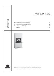
A name plate of heat-resistant material is affixed to the product<br />
on the underside of the burnchamber (Fig. 3 B). This contains<br />
information about identification and documentation for the<br />
product.<br />
2.0 Technical data<br />
ENGLISH<br />
Jøtul F <strong>162</strong><br />
Jøtul F <strong>162</strong> C Jøtul F <strong>163</strong><br />
Material: Cast iron Cast iron<br />
Finish: Black paint Black paint<br />
Fuel: Wood Wood<br />
Log length, max: 33 cm 33 cm<br />
Flue outlet: Top/rear Top/rear<br />
Flue pipe dimension: Ø150 mm, 177 cm 2 Ø150 mm, 177 cm 2<br />
cross section cross section<br />
Weight F <strong>162</strong> and F <strong>163</strong>: 115 kg<br />
115 kg<br />
Weight F <strong>162</strong> C: 134 kg<br />
Optional equipment: Cover for rear leg, Cover for rear leg,<br />
soapstone top soapstone top<br />
(not for F <strong>162</strong> C) (not for F <strong>162</strong> C)<br />
Dimensions, distances: See fig. 1 See fig. 1<br />
Product:<br />
Jøtul<br />
Room heater fired by solid fuel<br />
Standard<br />
Minimum distance to adjacent combustible materials:<br />
Minimum distance to adjacent combustible materials:<br />
Emission of CO in combustion products<br />
Flue gas temperature<br />
Nominal heat output<br />
Efficiency<br />
Operation range<br />
Fuel type<br />
Operational type<br />
The appliance can be used in a shared flue.<br />
Country Classification Certificate/ Approved by<br />
standard<br />
Norway Klasse II<br />
Sweden<br />
SP Sveriges Provnings- och<br />
OGC<br />
SP<br />
Forskningsinstitut AB<br />
SP Swedish National<br />
Testing and Research<br />
EUR Intermittent EN<br />
Institute<br />
Follow user`s instructions. Use only recommended fuels.<br />
Montage- und Bedienungsanleitung beachten.<br />
Verwenden Sie nur empfohlenen Brennstoffen.<br />
Respectez les consignes d'utilisation. Utilisez uniquement<br />
les combustibles recommandés.<br />
Serial no: Y-xxxx, Year: 200x<br />
Manufacturer:<br />
221546<br />
Jøtul AS<br />
POB 1441<br />
N-1602 Fredrikstad<br />
Norway<br />
:<br />
:<br />
:<br />
:<br />
:<br />
:<br />
:<br />
:<br />
On all our products there is a label<br />
indicating the serial number and<br />
year. Write this number in the<br />
place indicated in the installation<br />
instructions.<br />
Always quote this serial number when<br />
contacting your retailer or Jøtul.<br />
Serial no.<br />
Technical data according to EN 13240<br />
Jøtul F <strong>162</strong><br />
Jøtul F <strong>162</strong> C Jøtul F <strong>163</strong><br />
Nominal heat output: 5 kW 5 kW<br />
Flue gas mass flow: 5,0 g/s 5,0 g/s<br />
Recommended<br />
chimney draught: 12 Pa 12 Pa<br />
Efficiency: 83%@5,9 kW 82%@5,9 kW<br />
CO emission (13% O 2<br />
): 0,06% 0,10%<br />
CO emission (13% O 2<br />
): 792 mg/Nm 3 1242 mg/Nm 3<br />
Flue gas temperature: 260 o C 260 o C<br />
Operational type: Intermittent Intermittent<br />
Intermittent combustion is here taken to mean normal use of a<br />
fireplace. I.e. that a new flame chamber is lit as soon as the fuel<br />
has burnt down to the appropriate quantity of embers.<br />
45
ENGLISH<br />
300<br />
903<br />
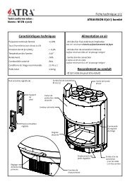
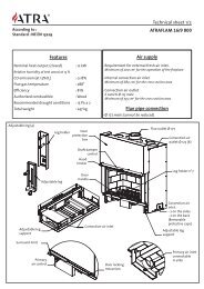
Fig. 1a<br />
Jøtul F <strong>162</strong> / Jøtul F <strong>163</strong> / Jøtul F <strong>162</strong> C<br />
Jøtul F <strong>162</strong> / Jøtul F <strong>163</strong><br />
Min. distance to combustible wall, base model<br />
Jøtul F <strong>162</strong> / F <strong>163</strong><br />
825<br />
600<br />
Hole in wall for external air<br />
Ø 100 mm<br />
Hole in floor for external<br />
air Ø 100 mm<br />
Jøtul F <strong>162</strong> C<br />
Combustible wall<br />
Min. measurements floor plate X,Y =<br />
According to national standards<br />
and regulations. See chapter 4.1<br />
* With semi-insulated chimney / covered flue pipe down<br />
towards the product.<br />
Min. distance to combustible wall, convection model<br />
Jøtul F <strong>162</strong> C<br />
200<br />
437<br />
200<br />
**150<br />
584<br />
**513<br />
** Jøtul F <strong>162</strong> C with semi-insulated chimney /<br />
covered flue pipe down towards the product.<br />
900061-P07<br />
200<br />
*150 412<br />
*362 647<br />
*592<br />
1000<br />
100<br />
**50<br />
340<br />
**290<br />
575<br />
**525<br />
1000<br />
413<br />
**363<br />
819<br />
**748<br />
450<br />
473<br />
500<br />
*400<br />
687<br />
*587<br />
972<br />
*831<br />
1207<br />
*1066<br />
Y<br />
300<br />
948<br />
235<br />
475<br />
93<br />
648<br />
147<br />
235<br />
93<br />
447<br />
119<br />
100<br />
789<br />
603<br />
X<br />
46
ENGLISH<br />
477<br />
712<br />
Jøtul F <strong>162</strong> / Jøtul F <strong>163</strong><br />
300<br />
525<br />
1000<br />
1000<br />
100<br />
312<br />
547<br />
300<br />
525<br />
1050<br />
1100<br />
100<br />
312<br />
547<br />
900<br />
312<br />
100<br />
1000<br />
1050<br />
150<br />
337<br />
800<br />
900<br />
900061-P07<br />
477<br />
712<br />
150<br />
337<br />
312<br />
100<br />
1000<br />
900<br />
800<br />
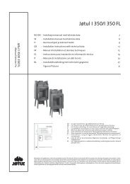
Fig. 1b<br />
External<br />
Integrated<br />
Min. distance to combustible wall protected by firewall:<br />
Combustible wall<br />
Firewall<br />
47
608<br />
ENGLISH<br />
External<br />
Integrated<br />
Jøtul F <strong>162</strong> C<br />
Min. distance to combustible wall protected by firewall:<br />
337<br />
100<br />
Combustible wall<br />
Firewall<br />
900061-P07<br />
281<br />
40<br />
1000<br />
40<br />
281<br />
516<br />
1000<br />
1000<br />
550<br />
500 600<br />
263<br />
50<br />
550<br />
373<br />
373<br />
608<br />
700<br />
700<br />
50<br />
263<br />
700<br />
281<br />
40<br />
40<br />
281<br />
516<br />
700<br />
337<br />
100<br />
1100<br />
Fig. 1c<br />
48
ENGLISH<br />
Air supply<br />
The outside air connection may be fitted directly to the Jøtul F <strong>162</strong>/<br />
F <strong>162</strong> C / F <strong>163</strong> through:<br />
• Through a flexible supply hose from the outside/chimney<br />
(only if the chimney has its own duct for external air) and to<br />
the product’s outside air connector.<br />
Fig. 2D, indirectly through an outside wall<br />
Fig. 2A, through an outside wall<br />
3.0 Safety<br />
NB! To guarantee optimal performance and safety, Jøtul stoves<br />
must be fitted by a qualified installer.<br />
Fig. 2B, through the floor and ground plate<br />
Any modifications to the product by the distributor, installer<br />
or consumer may result in the product and safety features not<br />
functioning as intended. The same applies to the installation of<br />
accessories or optional extras not supplied by Jøtul. This may<br />
also be the case if parts that are essential to the functioning<br />
and safety of the fireplace have been disassembled or removed.<br />
In all these cases, the manufacturer is not responsible or liable<br />
for the product and the right to make a complaint becomes null<br />
and void.<br />
Fig. 2C, through the floor and basement<br />
3.1 Fire Prevention Measures<br />
There is a certain element of danger every time you use your<br />
fireplace. The following instructions must therefore be followed:<br />
• The minimum safety distances when installing and using the<br />
fireplace are given in fig. 1.<br />
• Ensure that furniture and other flammable materials are not<br />
too close to the fireplace. Flammable materials should not be<br />
placed within 1 metre of the fireplace.<br />
• Allow the fire to burn out. Never extinguish the flames with<br />
water.<br />
• The fireplace becomes hot when lit and may cause burns if<br />
touched.<br />
• Only remove ash when the fireplace is cold. Ash can contain<br />
hot embers and should therefore be placed in a nonflammable<br />
container.<br />
• Ash should be placed outdoors or be emptied in a place where<br />
it will not present a potential fire hazard.<br />
In case of chimney fire:<br />
• Close all hatches and vents.<br />
• Keep the firebox door closed.<br />
• Check the loft and cellar for smoke.<br />
• Call the fire service.<br />
• Before use after a fire an expert must check the fireplace<br />
and the chimney in order to ensure that it is fully functional.<br />
49
ENGLISH<br />
4.0 Installation<br />
N.B. Check that the fireplace is free of any damage prior to<br />
commencing installation.<br />
The product is heavy! Make sure you have assistance when<br />
erecting and installing the fireplace.<br />
4.1 Floor<br />
Foundations<br />
Ensure that the floor is strong enough for the fireplace. See «2.0<br />
Technical data» for weights. It is recommended that flooring<br />
which is not fastened to the foundations – so-called floating<br />
flooring – is removed during installation.<br />
Combustible floor protection<br />
If the fireplace is to be mounted on a combustible floor, cover the<br />
floor under and in front of the fireplace with a plate of metal or<br />
other non- combustible material. The recommended minimum<br />
thickness is 0,9 mm.<br />
Any flooring made of combustible material, such as linoleum,<br />
carpets, etc. should be removed from under the floor plate.<br />
The plate must be in accordance with national laws and<br />
regulations.<br />
Contact your local building authority regarding restrictions and<br />
installation requirements.<br />
4.2 Walls (fig. 1a)<br />
Distance to wall made of combustible<br />
material<br />
You may use the fireplace with an uninsulated flue pipe provided<br />
the distances to walls made of combustible materials are as<br />
shown in fig. 1.<br />
Distance to wall with insulated flue pipe: Se fig. 1.<br />
Distance to walls covered by a firewall<br />
(fig. 1b and fig. 1c)<br />
Contact your local building authority regarding restrictions and<br />
installation requirements.<br />
4.3 Chimneys and flue pipes<br />
• The fireplace can be connected to a chimney and flue<br />
pipe approved for solid fuel fired appliances with flue gas<br />
temperatures specified in «2.0 Technical data».<br />
• The chimney’s cross-section must be at least as big as the<br />
flue pipe’s cross-section. See «2.0 Technical data» when<br />
calculating the correct chimney cross-section.<br />
• Several solid fuel fired appliances can be connected to the<br />
same chimney if the chimney’s cross-section is sufficient.<br />
• Connection to the chimney must be carried out in accordance<br />
with the installation instructions from the supplier of the<br />
chimney.<br />
• Before making a hole in the chimney the fireplace should be<br />
test-mounted in order to correctly mark the position of the<br />
fireplace and the hole in the chimney. See fig. 1 for minimum<br />
dimensions.<br />
• Ensure that the flue pipe is inclined all the way up to the<br />
chimney.<br />
• Use a flue pipe bend with a sweeping hatch that allows it to<br />
be swept.<br />
Be aware of the fact that it is particularly important that<br />
connections have a certain flexibility in order to prevent<br />
movement in the installation leading to cracks.<br />
N.B. A correct and sealed connection is very important for the<br />
proper functioning of the product.<br />
Chimney draught; See «2.0 Technical data». If the draught is<br />
too strong you can install and operate a flue damper to control<br />
the draught.<br />
4.4 Assembly prior to installation<br />
The product is delivered in a single packing case.<br />
After unpacking the stove check that the stove is free of any<br />
damage and that the regulating handles works.<br />
4.5 Selfclosing doormechanism<br />
The product is delivered with a selfclosing doormechanism. If<br />
wanted this can be removed.<br />
Fig. 3<br />
Firewall requirement<br />
The firewall must be at least 100 mm thick and be made of<br />
brick, concrete-stone or light concrete. Other materials and<br />
constructions with satisfactory documentation may also be used.<br />
Distance to non combustible walls<br />
By non combustible one means a non load-bearing wall of solid<br />
brickwork/concrete.<br />
A<br />
Contact your local building authority regarding restrictions and<br />
installation requirements.<br />
B<br />
1. Unscrew the screw and nut (fig. 3 A).<br />
2. Unhook and remove the spring.<br />
50
ENGLISH<br />
4.6 Fitting the flue pipe with the rear<br />
outlet<br />
The product is supplied from the factory with the smoke outlet<br />
fitted for the top outlet.<br />
Fig. 6a<br />
NB! Proceed as follows for installation with a rear outlet:<br />
Fig. 4<br />
1. Remove the baffle plate and exhaust defelctors (fig. 4 B).<br />
3. Unscrew the screws (fig. 6a C) and remove the cover (fig. 6a<br />
B) from the rear outlet from the inside of the burn chamber.<br />
Fig. 5<br />
Fig. 6b<br />
4. Knock out the removable cover plates (fig. 6b A).<br />
5. Attach the smoke outlet (fig. 6a A) on the inside of the burn<br />
chamber where the cover was.<br />
6. Install the cover (fig. 6a B) where the smoke outlet was.<br />
7. Refit the exhaust deflectors (fig. 4 B) and the baffle plate<br />
(fig. 4 A).<br />
2. Unscrew the screws (fig. 5 A) and remove the smoke outlet<br />
(fig. 5 B) from the top outlet from the inside of the burn<br />
chamber.<br />
51
ENGLISH<br />
4.7 Control of functions<br />
When the product is set up, always check the control functions.<br />
These shall move easily and function satisfactorily.<br />
Heating<br />
Fig. 7 B<br />
Jøtul F <strong>162</strong>, F <strong>162</strong> C and F <strong>163</strong> are equipped with the following<br />
control:<br />
Ignition vent/air vent<br />
Ignition<br />
Fig. 7 A<br />
• Leave the ignition-/air vent 40 mm (fig. 7 B) open when the<br />
wood has caught fire properly and is burning well.<br />
• Close the door.<br />
• You can then regulate the rate of combustion to give the heat<br />
you want by adjusting the air vent.<br />
• Check that the afterburning (secondary combustion) starts.<br />
This is best indicated by yellow, flickering flames in front of<br />
the holes under the baffle.<br />
• Open the ignition vent and air vent by pulling the handle all<br />
the way out. (Use a glove or something similar to protect your<br />
hand in case the handles are hot.)<br />
Adding firewood<br />
Stoke the stove frequently but only add small amounts of fuel at<br />
a time. If the stove is filled too full, the heat created may cause<br />
extreme stress in the chimney. Add fuel to the fire in moderation.<br />
Avoid smouldering fires as this produces the most pollution.<br />
The fire is best when it is burning well and the smoke from the<br />
chimney is almost invisible.<br />
4.7 Danger of overheating<br />
The fireplace must never be used in a manner that<br />
causes overheating<br />
Overheating occurs when there is too much fuel and/or too much<br />
air so that too much heat develops. A sure sign of overheating is<br />
when parts of the fireplace glow red. If this happens, reduce the<br />
air vent opening immediately.<br />
Seek professional advice if you suspect that the chimney is not<br />
drawing properly (too much/too little draught). For further<br />
information, see «4.0 Installation» (Chimney and flue pipe).<br />
• Place two logs at the bottom of the burn chamber and pile<br />
the kindling in layers.<br />
• Finally, place a medium-sized log on the top of the pile.<br />
• Place 2 or 3 briquettes or kindling sticks under the top layer<br />
of kindling and light the fire.<br />
52
ENGLISH<br />
5.0 Daily use<br />
Odours when using the fireplace for the first time<br />
When the fireplace is used for the first time, it may emit an<br />
irritating gas which may smell slightly. This happens because<br />
the paint dries.The gas is not toxic but the room should be<br />
thoroughly ventilated. Let the fire burn with a high draught until<br />
all traces of the gas have disappeared and no smoke or odours<br />
can be detected.<br />
5.2 Ash removal<br />
Jøtul F <strong>162</strong> / F <strong>162</strong> C / F <strong>163</strong> have an ash pan which makes it easy<br />
to remove the ash.<br />
Fig. 8<br />
5.1 Operation<br />
Heating advice<br />
NB: Logs that have been stored outdoors or in a cold room should<br />
be brought indoors 24 hours before use to bring them up to room<br />
temperature.<br />
There are various ways of heating the stove but it is always<br />
important to be careful about what you put in the stove. See the<br />
section on “Wood quality”.<br />
Wood quality<br />
By quality wood we mean most well-known types of wood such<br />
as birch, spruce and pine.<br />
The logs should be dried so that the moisture content is no more<br />
than 20%.<br />
To achieve this, the logs should be cut during the late winter. They<br />
should be split and stacked in a way that ensures good ventilation.<br />
The wood stacks should be covered to protect the logs from rain.<br />
The logs should be brought indoors during early autumn and<br />
stacked/stored for use in the coming winter.<br />
Be especially careful never to use the following materials as fuel<br />
in your fireplace:<br />
• Household rubbish, plastic bags, etc.<br />
• Painted or impregnated timber (which is extremely toxic).<br />
• Laminated wooden planks.<br />
• Driftwood<br />
These may harm the product and are also pollutants.<br />
NB: Never use petrol, paraffin, methylated spirit or similar liquids<br />
to light the fire. You may cause serious injury to yourself and<br />
damage to the product.<br />
Wood consumption<br />
Use of wood, with nominal heat emission: Approx. 1,6 kg/h.<br />
Another important factor for proper fuel consumption is that<br />
the logs are the correct size. The size of the logs should be:<br />
Kindling:<br />
Length: 23-33 cm<br />
Diameter: 2 - 5 cm<br />
Amount per fire: 6 - 8 pieces<br />
1. Scrape the ash through the grate (fig. 8 A) in the base plate<br />
and into the ash pan. Use a glove to grab the handle on the<br />
ash pan.<br />
2. Make sure that the ash pan doesn’t fill up so high that it keeps<br />
ash from coming through the grate into the pan.<br />
Firewood (split logs):<br />
Length: 23 - 33 cm<br />
Diameter: Approx. 8 cm<br />
Intervals for adding wood: Approximately every 45 minutes<br />
Size of the fire: 1,2 kg<br />
Amount per load: 2 pieces<br />
Nominal heat emission is achieved when the air vent is open<br />
approximately 57 %.<br />
53
ENGLISH<br />
6.0 Service<br />
Warning! Any unauthorised change to the product is not allowed.<br />
Only use original spare parts.<br />
6.1 Changing the burn plates/inner<br />
bottom plate<br />
Fig.9<br />
6.2 Changing the baffle plate<br />
• Lift the baffle plate (fig. 9-A) and remove it through the door.<br />
Access is then easy to baffle plate II (fig.9-B) if this needs to<br />
be removed. This is situated on 1 knob on the side burn plate<br />
and on the air manifold (fig. 9 D).<br />
• Edge it down and remove it through the door.<br />
For re-installation follow the same procedure in the opposite<br />
sequence.<br />
7.0 Maintenance<br />
7.1 Cleaning and soot removal<br />
Soot deposits may build up on the internal surfaces of the<br />
fireplace during use. Soot is a good insulator and will therefore<br />
reduce the fireplace’s heat output. If soot deposits accumulate<br />
when using the product, they can easily be removed by using a<br />
soot remover.<br />
In order to prevent a water and tar layer from forming in the<br />
fireplace, you should regularly allow the fire to burn hot in order<br />
to remove the layer. An annual internal cleaning is necessary to<br />
get the best heating effect from your product. It is a good idea<br />
to do this when cleaning the chimney and flue pipes.<br />
7.2 Sweeping flue pipes to the chimney<br />
Flue pipes must be swept through the flue pipe sweeping hatch<br />
or through the door opening.<br />
One of the baffles will have to be removed first in order to do this.<br />
7.3 Inspection of the fireplace<br />
Jøtul recommends that you carefully inspect your fireplace<br />
yourself after it has been swept/cleaned. Check all visible surfaces<br />
for cracks. Also check that all joints are sealed and that the gaskets<br />
are in the correct position. Any gaskets showing signs of wear or<br />
deformation must be replaced.<br />
Thoroughly clean the gasket grooves, apply ceramic glue<br />
(available from your local Jøtul dealer) and press the gasket well<br />
into place. The joint will dry quickly.<br />
• Remove the baffle plate (fig. 9 - A)<br />
• Remove the side burn plates (fig. 9-E) by lifting them up a<br />
little and then out. (Be aware if using tools, that vermiculite<br />
plates may be damaged by rough handling).<br />
• Unscrew the M8x25 mm screw on the rear burn plate (fig. 9-F)<br />
and remove the burn plate.<br />
• Then lift up and remove the inner bottom plate (fig. 9-C).<br />
Follow the same procedure for installation, but in the opposite<br />
sequence.<br />
7.4 Exterior maintenance<br />
Painted products may change colour after several years’ usage.<br />
The surface should be cleaned and brushed free of any loose<br />
particles before new paint is applied.<br />
54
ENGLISH<br />
8.0 Optional equipment<br />
8.1 Leg cover - outside air connection<br />
Cat. no. 361083<br />
8.2 Soapstone top - 50 mm, c0mplete<br />
Important! Soapstone top can not be used with Jøtul F <strong>162</strong> C.<br />
Cat. no. 361080<br />
9.0 Warranty<br />
Jøtul AS provides its customers with a ten-year warranty with the<br />
right to return external cast-iron items if they show defects as a<br />
result of faulty materials and/or manufacturing after the initial<br />
purchase/installation of the fireplace. The buyer is entitled to<br />
return the goods provided that the fireplace has been installed in<br />
compliance with current laws and regulations and in compliance<br />
with Jøtul’s installation and operating instructions.<br />
The warranty does not cover:<br />
The installation of optional extras, for example, to rectify local<br />
draught conditions, air supply or other circumstances beyond<br />
Jøtul’s control. The warranty does not cover consumables, such<br />
as burn plates, smoke baffles, fire grates, bottom grates, brick<br />
refractories, dampers and gaskets as they deteriorate over time<br />
due to normal wear and tear. The warranty does not cover damage<br />
caused as a result of using unsuitable fuel when lighting the fire,<br />
such as driftwood, impregnated and painted wood, plank offcuts,<br />
chipboard, etc. Overheating may easily occur if unsuitable fuel is<br />
used, i.e. the fireplace becomes red hot, which causes the paint<br />
to discolour and the cast iron parts to crack.<br />
The warranty is not valid for damage caused while the product<br />
is in transit from the distributor to the delivery address. The<br />
warranty is not valid either for damage caused by the use of<br />
non-original parts.<br />
55