Technical Manual (Revision 04-10) RP7016 - McCoy
Technical Manual (Revision 04-10) RP7016 - McCoy
Technical Manual (Revision 04-10) RP7016 - McCoy

You also want an ePaper? Increase the reach of your titles
YUMPU automatically turns print PDFs into web optimized ePapers that Google loves.
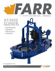
TECHNICAL MANUAL<br />
16” BUCKING UNIT<br />
m o d e l <strong>RP7016</strong><br />
• specifications<br />
• maintenance<br />
• operation<br />
www.superior-manf.com<br />
4225 Hwy 90 East • Broussard, LA 70518<br />
Phone: 337.837.8847 • Fax: 337.837.8839
© Copyright 20<strong>10</strong> Superior Manufacturing & Hydraulics (A Division Of <strong>McCoy</strong> Corporation), all rights reserved.<br />
This document is the property of Superior Manufacturing & Hydraulics and is supplied as reference information<br />
for users of our products. This document and the contents within are considered confidential information, not to<br />
be disclosed, copied, transmitted, transcribed in any form, or stored on any type of data storage media without the<br />
express written consent of Superior Manufacturing & Hydraulics.<br />
While continually striving to maintain accuracy, Superior Manufacturing & Hydraulics hereby states that the information<br />
contained in this technical documentation is subject to change without notice. If you feel this document<br />
does not meet your needs, please contact our sales office for the most current available documentation for your<br />
product.<br />
II
Table of Contents<br />
Section I ------------------------------------------------------<br />
General Description -------------------------------------------------- 2<br />
Safety Guidelines ---------------------------------------------------- 2<br />
Section II -----------------------------------------------------<br />
Installation --------------------------------------------------------- 2<br />
Start Up ----------------------------------------------------------- 2<br />
Section III -----------------------------------------------------<br />
Operation ---------------------------------------------------------- 2<br />
Make-up ----------------------------------------------------------- 2<br />
Break-out ---------------------------------------------------------- 2<br />
Section IV ----------------------------------------------------<br />
Maintenance -------------------------------------------------------- 3<br />
Daily- ------------------------------------------------------------- 3<br />
Monthly ----------------------------------------------------------- 3<br />
Annually ----------------------------------------------------------- 3<br />
Section V - - - - - - - - - - - - - - - - - - - - - - - - - - - - - - - - - - - - - - - - - - - - - - - - - - - - - -<br />
Hydraulic Power Unit- ------------------------------------------------- 3<br />
Section VI -----------------------------------------------------<br />
Specifications ------------------------------------------------------- 3<br />
Electric Motor ------------------------------------------------------- 3<br />
Hydraulic Oil -------------------------------------------------------- 3<br />
Chucking Capacity --------------------------------------------------- 3<br />
Torque Capacity ----------------------------------------------------- 3<br />
Section VII ----------------------------------------------------<br />
Bucking Unit Hydraulic Schematic ---------------------------------------- 4<br />
Control Console Hydraulic Schematic ------------------------------------- 5<br />
Control Console Electric Schematic -------------------------------------- 6<br />
Electric Proportional Schematic ----------------------------------------- 7<br />
Power Unit Hydraulic Schematic ----------------------------------------- 8<br />
Assembly Drawings -------------------------------------------------- 11<br />
1
SECTION I<br />
GENERAL DESCRIPTION:<br />
Your CLINCHER® Bucking Unit is a rugged, self-contained, continuously<br />
rotating unit designed to accurately make-up or break-out the<br />
threaded connections on tubular components such as oil and gas<br />
well drilling tools, casing, tubing, and similar equipment. The unit will<br />
accurately make-up and break-out thread connections without damage<br />
to the thread.<br />
Recommended Safety Guidelines<br />
The safety guidelines that follow are recommended by Superior<br />
Manufacturing & Hydraulics, and are in no way intended to supersede<br />
the specific health and safety regulations and guidelines of our<br />
client’s workplace. Workplace rules and regulations are the responsibility<br />
of the client.<br />
A. Work Apparel<br />
To ensure employee safety, it is recommended that the following<br />
PPE (Personal Protective Equipment) be worn when using and working<br />
around hydraulic equipment:<br />
1. Eye Protection (safety glasses)<br />
To avoid risk of eye damage due to:<br />
• fracture/failure of die inserts under load<br />
• fracture/failure of tool under load<br />
• failure of hydraulic hose or component under pressure<br />
2. Ear Protection (ear plugs)<br />
To prevent hearing damage due to:<br />
• electric motor and hydraulic systems noise<br />
• sudden and loud noises that may occur during the work<br />
process<br />
3. Head Protection (hard hat)<br />
To reduce danger due to:<br />
• overhead cranes and hooks<br />
• fracture/failure of die inserts under load<br />
• fracture/failure of tool under load<br />
4. Hand Protection (leather gloves)<br />
To avoid danger due to:<br />
• metal slivers on the tool or dies produced during the<br />
work process<br />
• chemicals used during the work process<br />
• failure of hydraulic hose or components under pressure<br />
5. Foot Protection (steel-toed boots)<br />
To prevent injury due to:<br />
• falling or rolling work pieces<br />
SECTION II<br />
INSTALLATION:<br />
1. Inspect unit carefully for shipping damage or missing parts.<br />
2. Position unit on a fairly flat and level floor leaving sufficient<br />
clearance on both ends to allow the insertion and removal<br />
of the longest tools expected to be serviced.<br />
3. Anchor the unit in place.<br />
4. Clean hydraulic hoses and quick disconnects.<br />
5. Attach all hoses that connect the control console to the<br />
Bucking Unit.<br />
6. Fill hydraulic reservoir with recommended hydraulic fluid<br />
filtered using 3 micron filter system. Filler cap/breather<br />
is accessible on left side of unit. Level indicator may be<br />
viewed through a window in front.<br />
7. Verify suction valve is open if present.<br />
8. Fill pump case with filtered hydraulic oil before connecting<br />
power.<br />
9. CAUTION: Check that main power supply matches name<br />
plate rating on motor in control console. Use of an incompatible<br />
power source will result in equipment damage and<br />
will void warranty.<br />
START UP:<br />
<strong>10</strong>. Connect power supply.<br />
11. Check motor rotation by jogging start/stop switch quickly.<br />
Reference the rotation plaque attached to the power unit.<br />
If rotation is incorrect, switch any two-phase wires at motor<br />
starter.<br />
1. Ensure both pressure relief valves are fully rotated counterclockwise<br />
to reduce pressure to minimum.<br />
2. Start motor and check for oil leaks in console. Hold back<br />
Backup Clamp Cylinder control lever in Open/Retract position<br />
and adjust Clamp Pressure Control until system pressure<br />
reads 1,000 psi. Cycle all valves fully several times to<br />
completely purge all air from the system.<br />
3. Check Bucking Unit and Hydraulic Power Unit for leaks.<br />
4. Check reservoir for proper fluid levels. Add filtered hydraulic<br />
fluid if level is below sight glass when all cylinders are extended.<br />
Fill until fluid level reaches midpoint in sight glass.<br />
If fluid level is below sight glass level, unit will not operate.<br />
SECTION III<br />
OPERATION<br />
The E-Stop is located on the control console, and must be pulled out<br />
for the unit to operate. Locate the start button on the motor starter.<br />
Push to start main drive motor.<br />
1. Start the motor.<br />
2. Move Tong Make Up / Break Out lever in either direction<br />
until the power tong completes a rotation.<br />
3. Hold Tailstock Clamp / Unclamp lever in the Unclamp<br />
position and adjust Clamp Pressure Control until system<br />
pressure reads 1,000 psi. Cycle all levers fully several times<br />
to completely purge all air from the system.<br />
4. Position work-piece near center of Headstock, shift the<br />
Tailstock Clamp / Unclamp lever to the Clamp position.<br />
Tailstock Clamp / Unclamp control lever must be left in the<br />
‘Clamp’ position while work-piece is in machine.<br />
5. Position Tailstock as close as possible to tong, allowing<br />
required space for thread travel. CAUTION: If adequate<br />
space is not left to accommodate thread travel, the backup<br />
will contact the tong, potentially damaging the equipment<br />
or tubular connection. Such damage is not covered by the<br />
warranty.<br />
6. Shift Headstock Clamp / Unclamp lever into Clamp position.<br />
7. Using Tong Make Up / Break Out control lever, apply makeup<br />
or break-out torque, then rotate headstock.<br />
MAKE-UP<br />
When making up connections, set relief valve to proper setting<br />
before rotating headstock.<br />
BREAK-OUT<br />
Set relief valve to proper setting before rotating headstock.<br />
2
SECTION IV<br />
MAINTENANCE<br />
DAILY:<br />
1. With all clamp cylinders fully extended, check hydraulic<br />
reservoir oil level on sight glass on front of console. Fill with<br />
filtered hydraulic fluid if needed until level reaches midpoint<br />
on sight glass.<br />
2. Inspect die inserts. Clear any debris from around clamp<br />
cylinders.<br />
WEEKLY:<br />
1. Remove dies and inspect jaw retainer bolt torque. Torque<br />
should be set to 180 ft-lbs.<br />
48”<br />
MONTHLY:<br />
1. Grease fittings.<br />
ANNUALLY (or following any system repair):<br />
1. Drain and clean hydraulic reservoir. Analyze contamination<br />
/ quality status of hydraulic oil (with the use of an analysis<br />
kit or by other third party means). Filter / replace oil as<br />
required.<br />
2.<br />
3.<br />
Remove and clean suction strainer.<br />
Refill reservoir with new filtered hydraulic oil.<br />
66”<br />
SECTION V<br />
HYDRAULIC POWER UNIT<br />
<strong>10</strong>5 1/2”<br />
The hydraulic power unit incorporates a number of pressure control<br />
and relief valves. These valves are correctly adjusted and set prior to<br />
shipment from our factory.<br />
CAUTION: Adjusting internal relief valves or pump compensator settings<br />
will void warranty.<br />
SECTION VI<br />
206”<br />
SPECIFICATIONS<br />
Console / Power Unit:<br />
Electric Motor: 50 Horsepower, 440 Volt, 3 phase, 60 Hertz<br />
Hyd. Oil Capacity: 90 gal.<br />
Hydraulic Oil: AW-68<br />
Overall Length: 42”<br />
Overall Width: 85”<br />
Overall Height: 52”<br />
Weight (approx.): 3,000 lbs.<br />
85” 42”<br />
52”<br />
Bucking Unit:<br />
Max. Torque: <strong>10</strong>5,000 ft-lbs<br />
Handle Length: 30”<br />
Overall Length: 206”<br />
Overall Width: 66”<br />
Overall Height: <strong>10</strong>5 1/2”<br />
Weight (approx.): 14,350 lbs.<br />
CHUCKING CAPACITIES<br />
2 3/8”” to 15 1/2” Diameter<br />
TORQUE CAPACITY<br />
Make-up <strong>10</strong>5,000 foot pounds / Break-out <strong>10</strong>5,000 foot pounds<br />
3
Bucking Unit<br />
Hydraulic Schematic<br />
CLINCHER® RP7000<br />
4
Control Console<br />
Hydraulic Schematic<br />
5
Control Console<br />
Electrical Schematic<br />
6
Electric Proportional Schematic<br />
7
Power Unit<br />
Hydraulic Schematic<br />
8
Page intentionally left blank<br />
9
<strong>10</strong><br />
Page intentionally left blank
<strong>RP7016</strong><br />
Continuously Rotating Bucking Unit<br />
Assembly Drawings<br />
C<br />
A<br />
B<br />
D<br />
E<br />
A<br />
B<br />
C<br />
D<br />
E<br />
Tail Stock Assembly -------------------------------------------------- 12<br />
Tong Assembly ----------------------------------------------------- 14<br />
Head Stock Assembly ----------------------------------------------- 14<br />
Tong Body Assembly ----------------------------------------------- 16<br />
Outer Manifold Assembly -------------------------------------------- 20<br />
Pinion Sprocket Assembly - ------------------------------------------- 22<br />
Drive Gear Assembly ----------------------------------------------- 24<br />
Clamp Cylinder Assembly ---------------------------------------------- 26<br />
Skid Assembly ------------------------------------------------------ 28<br />
Control Console / Power Unit Assembly - - - - - - - - - - - - - - - - - - - - - - - - - - - - - - - - - - - - - 31<br />
Notice: All drawings contained in this manual are the property of Superior Manufacturing & Hydraulics and are considered confidential.<br />
This information may not be used, disclosed, copied, or reproduced in any form, without the express written consent of<br />
Superior Manufacturing & Hydraulics.<br />
For third party component documentation used within this unit, please contact Superior Manufacturing & Hydraulics.<br />
11
300-7000-16<br />
Tail Stock Assembly<br />
27<br />
26<br />
22<br />
21<br />
20<br />
6 25<br />
19<br />
16<br />
4<br />
3<br />
17<br />
12<br />
24<br />
9<br />
9<br />
<strong>10</strong><br />
25<br />
7<br />
8<br />
6<br />
14<br />
13<br />
5<br />
23<br />
3 4 18 14 15 12<br />
11<br />
12
300-7000-16<br />
Tail Stock Assembly<br />
Item # Qty. Part Number<br />
Part Name<br />
1 20 1<strong>10</strong>3 1/2" LOCKWASHER<br />
2 20 1112-A 1/2"-13 x 2" HHCS<br />
3 14 1187 1 1/2-6 HEX NUT<br />
4 14 1223 1 1/2" LOCKWASHER<br />
5 4 194 5/8-11 NC NUT (194)<br />
6 7 309F-7000 TAILSTOCK SPACER<br />
7 4 309-7000 LOAD CELL BRACKET WELDMENT<br />
8 2 309B-7000 LOAD CELL BRACKET #2<br />
9 2 309D-7000 LOAD CELL LOCK PIN<br />
<strong>10</strong> 2 303B-6500 LOAD CELL DEAD PIN<br />
11 2 3<strong>10</strong>-7000 ROLLER SKATE WELDMENT<br />
12 4 3<strong>10</strong>E-7000 1-3/4" CAM FOLLOWER<br />
13 4 3<strong>10</strong>F-7000 3-1/2" CAM FOLLOWER<br />
14 14 1264 1"-13 X 2.5" HHCS<br />
15 14 1218 1" LW<br />
16 2 3<strong>10</strong>-7000-16 TAILSTOCK SIDE PLATE<br />
17 2 311-7000-16 TAILSTOCK BEARING CAP<br />
18 7 333-7000 1-1/2"-6 ALL THREAD ROD<br />
19 24 1773 SHCS Flat 1/2"-13 x 1"<br />
20 20 1774 SHCS Flat 1/2"-13 x 1-1/2"<br />
21 2 311A-7000-16 INNER TAILSTOCK BEARING CAP<br />
22 2 350-7000 TAILSTOCK INNER MOUNT PLATE<br />
23 2 508-3500 CHAIN BRACKET<br />
24 1 SG180-CPO 18" THRUST THIN SECTION BEARING<br />
25 1 SG180-XPO 18" FOUR CONTACT THIN SECTION BEARING<br />
26 6 400-7000-1 CLAMP CYLINDER ASSEMBLY<br />
27 1 351-7000-1 TAILSTOCK VISE ASSEMBLY<br />
13
250-7000-16<br />
Head Stock Vise Assembly<br />
7<br />
8<br />
4<br />
6<br />
5<br />
1<br />
2<br />
3<br />
14
250-7000-16<br />
Head Stock Vise Assembly<br />
Item # Qty. Part Number<br />
Part Name<br />
1 24 <strong>10</strong>27 WASHER, LOCK 3/8"<br />
2 24 1<strong>04</strong>6 HHCS 3/8-16 X 3/4<br />
3 12 1199 SCHCS 1/2"-13 x 2 1/2"<br />
4 12 222-7000 HEADSTOCK PIN<br />
5 24 222B-3500 CYLINDER PIN RETAINER<br />
6 1 240-7000-16 VISE WELDMENT<br />
7 1 253-7000-1 FLOW DIVIDER MOUNT ASSEMBLY<br />
8 6 400-3000-1 CLAMP CYLINDER ASSEMBLY<br />
15
200-7000-16<br />
Tong Body Assembly<br />
16
200-7000-16<br />
Tong Body Assembly<br />
2<br />
1<br />
13<br />
16<br />
23<br />
18<br />
19<br />
19<br />
4<br />
5<br />
11<br />
17<br />
18<br />
9<br />
12<br />
21<br />
6<br />
20<br />
13<br />
22<br />
12<br />
18<br />
17
200-7000-16<br />
Tong Body Assembly<br />
20<br />
23<br />
16<br />
15<br />
2<br />
14<br />
16<br />
DETAIL B<br />
SCALE 1 : 8<br />
12<br />
22<br />
<strong>10</strong><br />
7<br />
12<br />
A A<br />
23<br />
12<br />
20<br />
18<br />
B<br />
12<br />
18
200-7000-16<br />
Tong Body Assembly<br />
Item # Qty. Part Number<br />
Part Name<br />
1 32 <strong>10</strong>27 WASHER, LOCK 3/8"<br />
2 32 1<strong>04</strong>9 3/8"-16 X 1 1/2" HHCS<br />
3 80 1<strong>10</strong>3 1/2" LOCKWASHER<br />
4 12 12<strong>10</strong> 1"-8 NUT GR. 8<br />
5 12 1218 1" LW<br />
6 12 1291 1"-8 X 4" HHCS<br />
7 16 1309 DOWELL PIN 3/8" x 1-1/4"<br />
8 80 173 1/2"-13 x 2 1/4" HHCS<br />
9 1 200B-7000 TOP TONG PLATE<br />
<strong>10</strong> 1 200C-7000 BOTTOM TONG PLATE<br />
11 1 200D-7000 TONG CASE WELDMENT<br />
12 1 207-7000-1 PINION SPROCKET ASSEMBLY<br />
13 2 2<strong>10</strong>-7000-16 16" HEADSTOCK BEARING CAP<br />
14 1 2<strong>10</strong>A-7000 30" FOUR CONTACT THIN SECTION BEARING<br />
15 1 2<strong>10</strong>B-7000 30" RADIAL CONTACT THIN SECTION BEARING<br />
16 2 2<strong>10</strong>C-7000 GARLOCK OIL SEAL (21238-4352)<br />
17 1 211B-7000 MOTOR MOUNT WELDMENT<br />
18 1 235-7000-1 DRIVE GEAR ASSEMBLY<br />
19 13 253 SHCS 1/2"-13 x 4"<br />
20 1 290-7000-16 OUTER MANIFOLD ASSEMBLY<br />
21 1 2<strong>04</strong>-7000-16 HYDRAULIC SWIVEL<br />
22 1 2600-7000-1 SWIVEL KEEPER ASSEMBLY<br />
23 1 2600-7000-1 SWIVEL KEEPER ASSY.<br />
24 2 2701-7000 BOLT-ON SWIVEL KEEPER<br />
25 4 1173 3/4"-<strong>10</strong> x 1 3/4" HHCS<br />
26 4 1171 3/4" LOCKWASHER<br />
19
290-7000-16<br />
Outer Manifold Assembly<br />
1<br />
3<br />
2<br />
4<br />
20
290-7000-16<br />
Outer Manifold Assembly<br />
Item # Qty. Part Number<br />
Part Name<br />
1 1 212-7000 BULL GEAR SPROCKET<br />
2 6 249 1/2"-13 X 2" SHCS<br />
3 1 2021-7000 HUB WELDMENT<br />
4 6 1228 5/8 x 1 1/2 DOWEL PIN<br />
21
207-7000-1<br />
Pinion Sprocket Assembly<br />
11<br />
5<br />
<strong>10</strong><br />
2<br />
7<br />
9<br />
8<br />
6<br />
1<br />
4<br />
3<br />
22
207-7000-1<br />
Pinion Sprocket Assembly<br />
Item # Qty. Part Number<br />
Part Name<br />
1 6 1<strong>10</strong>3 1/2" LOCKWASHER<br />
2 6 1132-B SCHCS 1/2"-13 X 1 3/4"<br />
3 6 173 1/2"-13 x 2 1/4" HHCS<br />
4 2 1771 1/4" NPT GREASE ZERT<br />
5 1 1772 SHCS Flat 1/2"-13 x 1"<br />
6 1 206A-7000 HEADSTOCK BEARING CAP<br />
7 1 208-7000 HEADSTOCK TOP BEARING CAP<br />
8 1 209-7000 PINION SPROCKET<br />
9 2 209-7000-1 PINION SPROCKET BEARING<br />
<strong>10</strong> 1 209B-7000 HIGH PINION GEAR<br />
11 1 507D-7000 DRIVE GEAR RETAINER<br />
23
235-7000-1<br />
Drive Gear Assembly<br />
A<br />
5<br />
2<br />
A<br />
1<br />
4<br />
6<br />
3<br />
SECTION A-A<br />
SCALE 1 : 8<br />
24
235-7000-1<br />
Drive Gear Assembly<br />
Item # Qty. Part Number Part Name<br />
1 <strong>10</strong> <strong>10</strong>81 7/16" LOCKWASHER<br />
2 <strong>10</strong> <strong>10</strong>85-A HHCS 7/16"-20<br />
3 1 1132-C SHCS Flat 1/2"-20 x 1"<br />
4 1 209C-7000 MOTOR DRIVE GEAR<br />
5 1 235-7000 HYDRAULIC MOTOR<br />
6 1 507D-7000 DRIVE GEAR RETAINER<br />
25
400-7000-1<br />
Clamp Cylinder Assembly<br />
8<br />
14<br />
6 9<br />
O-RING PART OF<br />
PISTON ROD ASSY.<br />
A<br />
4<br />
11<br />
12<br />
6<br />
9<br />
1<br />
2<br />
7<br />
A<br />
5<br />
B<br />
C<br />
D<br />
SECTION A-A<br />
DETAIL D<br />
SCALE 1 : 4<br />
<strong>10</strong><br />
15<br />
DETAIL B<br />
SCALE 1 : 4<br />
DETAIL C<br />
SCALE 1 : 4<br />
26
400-7000-1<br />
Clamp Cylinder Assembly<br />
Item # Qty. Part Number<br />
Part Name<br />
1 2 <strong>10</strong>23-N 5/16" X 5/8" DOWEL PIN<br />
2 2 1112 1/2"-13 x 1 1/2" HHCS<br />
3 1 1570 3/8" MNPT X 3/8" MJIC STRAIGHT<br />
4 2 1577-A 90 3/8" MNPT X 3/8" MJIC<br />
5 2 260 5/8-11 x 2 SHCS<br />
6 1 400-7000 CYLINDER BLOCK HOUSING WELDMENT F/ 22"<br />
7 1 401-3000-1 END PLATE WELDMENDT<br />
8 1 402-3000 STANDARD JAW HOLDER<br />
9 1 4<strong>04</strong>-7000 SEAL PLATE WELDMENT<br />
<strong>10</strong> 1 405-3000 SPLIT RING<br />
11 2 408-3000 3/8" WASHER<br />
12 2 91253B SHCS Flat 1/2"-13 x 7/8"<br />
13 1 400C-3000 SEALS KIT<br />
14 1 403-7000-2 PISTON/ROD ASSEMBLY<br />
15 1 DTI1602 DOVETAIL STRIP DIE (1 1/4" x 1/2" x 5")<br />
27
500-7000-16<br />
Skid Assembly<br />
A<br />
19<br />
18<br />
21<br />
17<br />
22 23<br />
24<br />
B<br />
16<br />
8<br />
12 5<br />
20<br />
15<br />
11<br />
DETAIL A<br />
SCALE 1 : 6<br />
14<br />
9<br />
13<br />
11<br />
DETAIL B<br />
SCALE 1 : 4<br />
4<br />
11<br />
9<br />
7<br />
3<br />
3<br />
4<br />
<strong>10</strong><br />
19<br />
8<br />
28
500-7000-16<br />
Skid Assembly<br />
Item # Qty. Part Number Part Name<br />
1 1 <strong>10</strong>27 WASHER, LOCK 3/8"<br />
2 1 1<strong>04</strong>8 3/8"-16 X 1 1/4" HHCS<br />
3 8 1<strong>10</strong>3 1/2" LOCKWASHER<br />
4 8 11<strong>10</strong> 1/2"-13 x 1" HHCS<br />
5 4 246 1/2-13 x 1 SHCS<br />
6 1 500A-7000-16 16' SKID WELDMENT F/ 16" BREAKOUT UNIT<br />
7 1 502B-6500 TRAVEL SPROCKET SHAFT<br />
8 4 508-3000 1 1/2" BEARING<br />
9 2 509-3000 TRAVEL SPROCKET<br />
<strong>10</strong> 1 5<strong>10</strong>B-3000 TRAVEL SPROCKET SHORT SHAFT<br />
11 3 5<strong>10</strong>C-3000 TRAVERSE SPROCKET KEY<br />
12 1 511-6500 TRAVEL MOTOR<br />
13 1 515A-3000 1 1/2" L-COUPLING<br />
14 1 515B-3000 MODIFIED 1" L- COPLING<br />
15 1 515C-3000 L1<strong>10</strong> SPIDER<br />
16 1 515-7000 SPROCKET COVER WELDMENT<br />
17 4 540-3000 BUMPER STOP ASSEMBLY<br />
18 6 552A-7000-16 LONG GRATING<br />
19 1 556-7000-22 TRAVEL CHAIN<br />
20 2 6-<strong>10</strong>_f5ox-s 5/8" ORING X 3/8" MJIC<br />
21 4 528-3000 BUMPER STOP<br />
22 8 1171 3/4” LOCKWASHER<br />
23 8 1174 3/4”-<strong>10</strong> x 2 1/4” HHCS<br />
24 4 525-300-1 BUMPER STOP WELDMENT<br />
29
30<br />
Page intentionally left blank
<strong>10</strong>0-7000-1<br />
Control Console / Power Unit Assembly<br />
5<br />
5<br />
4<br />
3<br />
3<br />
6<br />
1<br />
5<br />
9<br />
8<br />
7<br />
<strong>10</strong><br />
1<br />
Item # Qty. Part Number<br />
Part Name<br />
1 1 <strong>10</strong>0-6500 CONSOLE WELDMENT<br />
2 2 12 WFTX-S 3/4" BULKHEAD CONNECTOR MNPT<br />
3 2 130-6500 PRESSURE CONTROL VALVE<br />
4 1 132-6500 0-<strong>10</strong>00 PSI GAUGE<br />
5 3 133-6500 0-3000 PSI GAUGE<br />
6 1 150-7000-22 TOP COVER PLATE<br />
7 1 152-6500 BULKHEAD COVER<br />
8 1 CLEBU12<strong>10</strong>-01 TORQUE COMPUTER MOUNT (EXTENDED)<br />
9 1 Stop Button<br />
<strong>10</strong> 1 Power Unit<br />
31