Parts List and Operating Instructions for Bead Breaker Model ... - Esco
Parts List and Operating Instructions for Bead Breaker Model ... - Esco
Parts List and Operating Instructions for Bead Breaker Model ... - Esco

You also want an ePaper? Increase the reach of your titles
YUMPU automatically turns print PDFs into web optimized ePapers that Google loves.
REV0709<br />
<strong>Parts</strong> <strong>List</strong> <strong>and</strong> <strong>Operating</strong> <strong>Instructions</strong> <strong>for</strong><br />
<strong>Bead</strong> <strong>Breaker</strong><br />
<strong>Model</strong> 10104<br />
∆ Not included with 10215 or 10216 assembly.<br />
• Indicates parts in 10216 ram assembly.<br />
Balance of parts not indicated with (∆ or •) are included in 10215 frame<br />
assembly.
REV0709<br />
<strong>Parts</strong> <strong>List</strong> <strong>and</strong> <strong>Operating</strong> <strong>Instructions</strong> <strong>for</strong><br />
<strong>Bead</strong> <strong>Breaker</strong> <strong>Model</strong> 10104<br />
ITEM PART NO<br />
NO. NO. REQ’D DESCRIPTION<br />
1• TO-100-RA 1 Cylinder (Includes trunion [item 3])<br />
2• TO-100-18 1 Trunion<br />
3 TO-100-17 4 Lock Washer<br />
4 TO-100-16 4 Hex Nut<br />
5 TO-100-9 1 Tie Bolt<br />
6 TO-100-6R 1 Side Plate (right)<br />
7 TO-100-15 2 Sq. Hd. Set Screw<br />
8 TO-100-1R 1 Bottom Clamp Jaw (right)<br />
9 TO-100-2R 1 Top Clamp Jaw (right)<br />
10• TO-100-20 1 Set Screw<br />
11∆ TO-100-23 6 Wedge<br />
12 TO-100-11 1 Spring<br />
13• TO-100-19 1 Spade<br />
14 TO-100-11 2 Spring Pin<br />
15 TO-100-9 1 Clamp Jaw Pin<br />
16 TO-100-7 2 Hinge Pin (see 202825)<br />
17 TO-100-5 1 Spacer<br />
18 TO-100-3 2 Center<br />
19 TO-100-14 1 H<strong>and</strong> Screw<br />
20 TO-100-4 1 Swivel Nut<br />
21 TO-100-2L 1 Top Clamp Jaw (left)<br />
22 TO-100-1L 1 Bottom Clamp Jaw (left)<br />
23 TO-100-6L 1 Side Plate (left)<br />
24 TO-100-12 1 Stop Screw<br />
25 TO-100-13 1 Spacer<br />
26• TO-100-44 1 Adapter<br />
SAFETY PRECAUTIONS<br />
∆ Not included with 10215 or 10216<br />
assembly.<br />
• Indicates parts in 10216 ram assembly.<br />
Balance of parts not indicated with (∆ or<br />
•) are included in 10215 frame assembly.<br />
Follow the tire manufacturer’s instructions <strong>and</strong> the vehicle manufacturer’s instructions to deflate, demount, mount, <strong>and</strong> inflate tires.<br />
If the following procedure does not apply to your specific rim, contact the rim manufacturer <strong>for</strong> the correct procedure. A contact the<br />
United States Department of Transportation, Washington DC 20594 <strong>for</strong> the publication “Multipiece Rim/Wheel Matching Charts.”<br />
DANGER: To help prevent the possibility of serious personal injury or death.<br />
• Do NOT use the <strong>Bead</strong> <strong>Breaker</strong> without reading <strong>and</strong> underst<strong>and</strong>ing the following safety precautions <strong>and</strong> operating instructions.<br />
• Wear safety glasses at all times.<br />
• Only trained professional technicians who are familiar with this type of equipment <strong>and</strong> its correct usage should use the <strong>Bead</strong> <strong>Breaker</strong>.<br />
• Use hardwood blocks under the jack regardless of the type of surface. Crib the vehicle with blocks while raising it.<br />
• St<strong>and</strong> to one side when applying hydraulic pressure. The <strong>Bead</strong> <strong>Breaker</strong> creates an extremely high <strong>for</strong>ce at a moderate hydraulic pressure; if<br />
the <strong>Bead</strong> <strong>Breaker</strong> slips off the flange, it could cause serious injury or death.<br />
• NEVER hammer on an inflated or partly inflated tire/rim assembly.<br />
• NEVER weld, heat, brase, or rework rim components that are broken cracked or damaged. Replace bad parts with<br />
new or undamaged used parts of the same size <strong>and</strong> shape. If you are in doubt, contact the wheel distributor or<br />
manufacturer.<br />
• Do NOT weld on an inflated tire/rim assembly because an explosion could occur.<br />
• Always use a safety cage or safety chains when you are inflating a tire.
REV0709<br />
<strong>Parts</strong> <strong>List</strong> <strong>and</strong> <strong>Operating</strong> <strong>Instructions</strong><br />
MOUNTING <strong>and</strong> INFLATION<br />
1. Block the wheels opposite the jack be<strong>for</strong>e placing the jack in position.<br />
2. Inspect all rim components <strong>for</strong> damage. All badly worn, cracked, severely rusted components must be replaced.<br />
3. Clean <strong>and</strong> repaint as required. Be careful to keep paint out of the lock ring groove in the gutter.<br />
4. Do not use a steel hammer on the rim or rim components. If you have to reposition tire components be<strong>for</strong>e inflation, use a<br />
rubber, plastic, or brass-faced hammer.<br />
5. All side <strong>and</strong> lock rings must be in place be<strong>for</strong>e inflating a tire.<br />
6. Inflate the tire to 10 PSI <strong>and</strong> check all components <strong>for</strong> the correct position.<br />
7. Continue inflating the tire until the tire bead fully seats. Let the tire fully deflate. Inflate the tire again to the recommended<br />
pressure. NOTE: Tires must be inflated <strong>and</strong> loaded only to the manufacturer’s limit. Under no circumstances<br />
should a vehicle be run with only one tire of a dual assembly. If a tire/rim assembly does no slide over a cast spoke<br />
wheel. Do NOT try to <strong>for</strong>ce the assembly by hammering. Deflate the tire <strong>and</strong> inspect the components <strong>for</strong> distortion or<br />
incorrectly seated components or lock rings.<br />
OPERATING INSTRUCTIONS<br />
DANGER: To help prevent the possibility of serious personal injury or death,<br />
• Do not remove a wheel or a rim component (such as rim clamps or nuts) without first removing the valve core <strong>and</strong><br />
letting the tire(s) deflate. Insert a thin piece of wire through each valve stem to be sure the passage is not blocked.<br />
• Always crib the vehicle with blocks in case the jack slips or fails.<br />
• Always st<strong>and</strong> to one side of the rim when applying hydraulic pressure.<br />
1. Attach the TO-100 frame assembly to the outer rim flange by<br />
slipping the clamping jaws over the outer edge of the flange.<br />
See Figure 1. Use <strong>Bead</strong> <strong>Breaker</strong> <strong>Model</strong>s BB1600 or 64110 if<br />
the TO-100 <strong>Bead</strong> <strong>Breaker</strong> cannot be attached to the flange.<br />
Figure 1<br />
2. Securely tighten adjusting screws at bottom of jaws. Set h<strong>and</strong> screw<br />
against lock ring <strong>and</strong> adjust until jaw assembly is in a right angle position<br />
to the plane of the flange. See Figure 2.<br />
Figure 2
REV0709<br />
<strong>Parts</strong> <strong>List</strong> <strong>and</strong> <strong>Operating</strong> <strong>Instructions</strong><br />
3. With spade tip down <strong>and</strong> cylinder in retracted position, insert<br />
spade <strong>and</strong> cylinder assembly between open sides of frame.<br />
Place spade tip between tire bead <strong>and</strong> rim flange. See Figure 3.<br />
Figure 3<br />
4. Lift cylinder until trunion engages frame shoulder <strong>and</strong> move stop<br />
screw into support cylinder. See Figure 4.<br />
Figure 4<br />
5. Apply pressure to cylinder <strong>and</strong> spade by means of pump until spade<br />
has moved tire bead toward center of rim assembly far enough to<br />
permit the placing of a bead wedge between bead <strong>and</strong> flange on<br />
each side of the tool. Do not st<strong>and</strong> in front of tool is under pressure.<br />
See Figure 5.<br />
Figure 5<br />
6. Release pump pressure. Remove spade <strong>and</strong> cylinder<br />
assembly from frame. Loosen clamping jaw bolts <strong>and</strong> remove<br />
from flange. Move to spot approximately 90° from first<br />
application (either direction) <strong>and</strong> repeat entire procedure.<br />
Repeat procedure until tire bead is free. Four or five<br />
applications usually accomplishes this. See Figure 6.<br />
Figure 6
REV0709<br />
REPAIR PARTS FOR TO-100-HA<br />
PART NUMBER QTY DESCRIPTION<br />
TO-100-1R 1 Bottom Clamp Right<br />
TO-100-1L 1 Bottom Clamp Left<br />
TO-100-2R 1 Top Clamp Right<br />
TO-100-2L 1 Top Clamp Left<br />
TO-100-3 1 Center Link<br />
TO-100-4 1 Swivel Nut<br />
TO-100-5 1 Spacer<br />
TO-100-6L 1 Side Plate Left<br />
TO-100-6R 1 Side Plate Right<br />
TO-100-7 1 Hinge Pin (see 202825)<br />
TO-100-8 1 Clamp Pin<br />
TO-100-9 1 Tie Bolt<br />
TO-100-10 1 Spring<br />
TO-100-11 1 Spring Pin<br />
TO-100-12 1 Stop Screw<br />
TO-100-13 1 Spacer<br />
TO-100-14 1 H<strong>and</strong> Screw<br />
TO-100-15 2 Square Set Screw<br />
TO-100-16 4 Nut<br />
TO-100-17 4 Washer<br />
TO-100-18 1 Trunion<br />
TO-100-19 1 Spade<br />
TO-100-20 1 Set Screw<br />
TO-100-23 6 Wedges<br />
TO-100-44 1 Adapter<br />
TO-100-RA<br />
Ram Assembly<br />
RC102K<br />
Repair Kit
REV0709<br />
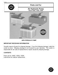
Repair <strong>Parts</strong> Sheet<br />
Turbo II Air Hydraulic Pump<br />
<strong>Model</strong> 10500, 10502, 10504<br />
(AHP-15T, AHP-25TP, AHP-35T))<br />
Install all kit components to insure optimum per<strong>for</strong>mance of the repaired unit.<br />
NOTE: Storing the pump in the vertical position may cause it to lose its prime. If pump loses its prime:<br />
1. Remove cover.<br />
2. Remove relief valve.<br />
3. Fill chamber with oil.<br />
4. Replace relief valve. Apply Loctite 545 to threads <strong>and</strong> torque to 10–12 ft-lbs. [14–16 Nm].<br />
5. Replace pump cover. Tighten fasteners according to torquing sequence on Figure 1, page 2.<br />
AHP-15T<br />
AHP-35T<br />
AHP-25TP<br />
(10502)<br />
Contents<br />
Figure 1 — Treadle Assembly, AHP-15T, AHP-25TP 2 Figure 5 — Air Motor Assembly 6<br />
Figure 2 — Treadle Assembly, AHP-35T 3 Figure 6 — Cover Assembly 7<br />
Figure 3 — Hydraulic Section Detail 4 Figure 7 — Release Valve 8<br />
Figure 4 — Seal Push Tool 5
REV0709<br />
Torque to 17-19 in-lbs. [2 Nm]<br />
Torque to 6-8 in-lbs. [8-11 Nm]<br />
Torque to 17-19 in-lbs. [3 Nm]<br />
tighten using sequence shown on<br />
Both Sides<br />
The gasket is to be oriented with<br />
this opening in the same corners<br />
Sight glass location<br />
as the fill plug on the cover.<br />
on reservoir<br />
Gasket orientation detail <strong>and</strong><br />
Torque to 17-19 in-lbs [2 Nm].<br />
cover screw torquing sequence<br />
Items 120 <strong>and</strong> 121 shown in this view only,<br />
<strong>for</strong> optional mtg. bracket "B" designation.<br />
Figure 1<br />
Repair <strong>Parts</strong> <strong>List</strong> <strong>for</strong> Figure 1<br />
Item Part Number Qty. Description Item Part Number Qty. Description<br />
1 DA12288022 1 Sight Glass 92 DC1523028 2<br />
Slotted Hex Washer Head<br />
Scr.<br />
2 B1908503 1 O Ring 94 DA4849218 1 Treadle<br />
50 DC4321900SR 1 Reservoir, 2 L, Yellow 95 DA4236242 2 Shoulder Screw<br />
DC4320900SR 1 Reservoir, 5 L, Black 111 DC1146026 2 Decal, <strong>Esco</strong> (AHP-15T, AHP-35T)<br />
51 DC4027167 1 Reservoir Gasket, 2 L DC825026 2 Decal, <strong>Esco</strong> (AHP-25TP)<br />
DC714517 1 O-ring Gasket Cover, 5 L 110 DA4296026 1 <strong>Model</strong> No. Decal<br />
54 DA5938028 12 Hi Lo Screw 120 DA5389111 1 Mounting Bracket<br />
90 DA8625116 1 Muffler 121 DA5938028 4 Hi Lo Screw<br />
91 DA5690098 1 Muffler Cover
REV0709<br />
Items included in pump repair kit PAT1100K.<br />
Torque to 15-20 lb-in.<br />
55<br />
56<br />
54<br />
56<br />
Torque to 15-20 lb-in. Tighter using sequence<br />
shown on "Gasket Orientation Detail".<br />
(8 - places)<br />
53<br />
52<br />
51<br />
Torque to 25-30 lb-in. tighten<br />
using sequence shown on<br />
4<br />
3<br />
2<br />
5 1 3<br />
10<br />
7<br />
1<br />
9 8<br />
5<br />
6<br />
2<br />
4<br />
6<br />
Gasket Orientation Detail <strong>and</strong><br />
57<br />
58<br />
Figure 2<br />
Repair <strong>Parts</strong> <strong>List</strong> <strong>for</strong> Figure 2<br />
Item Part Number Qty. Description Item Part Number Qty. Description<br />
1 DA11741025 1 2 Gallon reservoir 53 B1221503 1 0-Ring<br />
2 DA11720037 1<br />
Reservoir Gasket Top<br />
Plate<br />
54 B2521028 8 BHC Screw- .250-20x. 75 lg.<br />
3 DA11730101 1 Plate 55 DC4487028 4 Cap screw<br />
4 B2525028 10 BHC Screw 56 DC1063108 12 Sealing Washer<br />
5 B1015066 14 Washer, Lock, .250 57 B1015066 4 Lock Washer .250<br />
6 B1001122 14 Hex Nut (.250-20) 58 B1001122 4 Hex Nut (.250-20)<br />
51 DA7933167 1 Gasket 110 DA6197028 4 Screw<br />
52 DC460900SR 1 Intake Tube
REV0709<br />
Items included in pump repair kit PAT1100K.<br />
Notes:<br />
1. Lubricate seals with moderate amount of DS-ES grease.<br />
2. Apply Loctite 545 on threads, <strong>and</strong> apply 10–12 ft-lbs. [14-16 Nm] of torque to item #6. Set at 10,400 to<br />
11,000 psi.<br />
3. Apply Loctite 243 on threads <strong>and</strong> apply 34–41 ft-lbs. [46-55 Nm] of torque to item #8 <strong>and</strong> #13<br />
4. Apply one drop of Loctite 242 on threads, <strong>and</strong> apply 16–18 ft-lbs. [22-24 Nm] of torque to item #18<br />
5. Items #24 <strong>and</strong> #25 are installed finger tight.<br />
6. Apply a 1/2 bead of Loctite 243 on threads <strong>and</strong> apply 38-45 ft-lbs. of torque to item #8.<br />
14 — See note #1<br />
15 — See note #1<br />
14 — See note #1<br />
13 — See note #3<br />
See note #6 — 8<br />
See note #2 — 6<br />
12<br />
11<br />
10<br />
9<br />
7<br />
20<br />
21<br />
22<br />
23 — See note #1<br />
11<br />
19<br />
9<br />
7<br />
See note #6—8<br />
2<br />
1<br />
18 — See note #4<br />
17 — Bearing to be installed with<br />
chamfer to the outside<br />
16 — Install U-cup with groove<br />
side towards mounting<br />
See note #5 - 53<br />
5 — Sharp edge away<br />
from mounting bracket<br />
4<br />
3 — See note #1<br />
See note 4 #5 - 53<br />
SECTION A-A<br />
Figure 3
REV0709<br />
Repair <strong>Parts</strong> <strong>List</strong> <strong>for</strong> Figure 3<br />
Item Part Number Qty. Description Item Part Number Qty. Description<br />
1 DC114030 1 Hydraulic Cylinder, Turbo 10 KSI 14 DA4974367 2 Backup Ring<br />
2 DA4298108 1 Washer 15 B1016803 2 O-Ring – Global<br />
3 B1258503 2 O-Ring 16 CB918041 1 U-Cup 10 KSI<br />
4 DA4287111 1 Mtg. Bracket 17 CB624108 1 Bearing 10 KS<br />
5 DA4343044 1 Bowed Ret. Ring 18 DA1204044 1 Bearing Retainer 10 KSI<br />
6 DA8802900SR 1 Relief Valve Assembly 19 DA6911210 1 Conical Spring<br />
7 DA3811167 2 Copper Gasket 20 DA4285110 1 Spring<br />
8 DC283290SR 11 2 Seat 21 DA6600108 1 Rubber Washer 10 KSI<br />
9 B1007016 2 1/4" Dia. Ball 22 DA4284108 1<br />
Spring Washer, Turbo, 10<br />
KSI<br />
10 DA4874110 1 Conical Spring 23 CB180040 1 Plunger, 10 KSI<br />
11 DA3682013 2 Ball Guide 24 DC4440 1 Poppet<br />
12 DC170167 1 Copper Gasket 52 DC442900SR 1 Intake Tube Assembly<br />
13 DC5268SR 1 Pressure Tube 10 KSI 53 B1221503 1 O-Ring Ref. C403503<br />
Items included as part of Repair Kit: (DC2222900K) Also included in complete Pump Repair Kit PATG1100K.<br />
Figure 4, U-cup Installation Tools
REV0709<br />
— See note #2<br />
See note #6<br />
See note #4 —<br />
— See note #2<br />
— See note #2<br />
— See note #5<br />
— See note #1<br />
Notes:<br />
See note #7<br />
See note #7<br />
See note #2 <strong>and</strong> #7<br />
1. Apply 20-25 lb-in [1 Nm] of torque to Item #30.<br />
2. Lubricate seals with a moderate amount of DS-ES grease.<br />
3. Lubricate seal <strong>and</strong> bore with a light coating of HF100 Hydraulic Fluid.<br />
4. Install Item #39 into Item #40 until firmly seated.<br />
5. Install screws in a circular pattern. Apply 39–55 lb-in [5 Nm] of torque to<br />
Item #41. Check torque of first screw.<br />
6. Bend legs on Item #43 to retain clip after assembly.<br />
7. After installing the air motor <strong>and</strong> Item #47 on the mounting bracket (not<br />
shown), assemble Item #48 <strong>and</strong> #49 then apply 30–40 lb-in [4 Nm] of torque<br />
to Item #49.<br />
Figure 5<br />
Repair <strong>Parts</strong> <strong>List</strong> <strong>for</strong> Figure 5<br />
Item Part Number Qty. Description Item Part Number Qty. Description<br />
30 DA7085028 1 Screw – .250-20 Special 39 A1006245 1 1/16 Flush Plug w/Sealant<br />
31 DA3706120 1 B/U Washer 41 DC2261628 4 Screw, Torx (.25-20 x .75 lg.)<br />
32 DC2234051 1 Piston 42 DC2182099 1 Extension Fitting, Air Motor<br />
33 B1013503 1 O-Ring 43 DA5521149 1 Retaining Pin<br />
34 B1001503 1 O-Ring(.12 x .25 x .06) 44 DA4122051SR 1 Air Motor Piston Assembly<br />
35 DC2200900SR 1 Air Motor, Complete 47 B1282503 1 O-Ring<br />
36 B1260503 1 O-Ring 48 DA2687111 2 Clamp Brk.
REV0709<br />
37 B1014503 1 O-Ring Ref M760041 49 DA2686299 1 Hose Clamp<br />
38 B1009503 4 O-Ring Ref K1041<br />
Items included in <strong>and</strong> available only as part of Repair Kit DC2234900SR.<br />
Also included in complete Pump Repair Kit PATG1100K.<br />
66 - Apply 17-19 lb-in [2 Nm]<br />
CAUTION: Do not attempt to remove or otherwise service<br />
the air-switch button (item 73). Removal will damage the<br />
sealing surfaces molded in the reservoir cover.<br />
73<br />
65<br />
64<br />
63<br />
61 Apply Lubriplate 630-AA<br />
72<br />
Install screw until O-Ring<br />
71<br />
88 - Bend clip to retain<br />
70<br />
motor assembly.<br />
SECTION C-C<br />
85 -Locking tabs on retaining ring<br />
Lubricate with Lubriplate DS-ES grease - 80<br />
Lubricate with Lubriplate DS-ES grease - 79<br />
Apply Loctite PST 59241 - 78<br />
or Vibraseal to threads.<br />
must be pointed away from spring<br />
84<br />
Fill cap / vent plug<br />
77<br />
82<br />
83<br />
81<br />
SECTION B-B<br />
67<br />
66 - Apply 17-19 lb-in [2 Nm] of torque<br />
68<br />
60<br />
69<br />
86 - Apply adhesive side of gasket to cover
REV0709<br />
Figure 6<br />
Repair <strong>Parts</strong> <strong>List</strong> <strong>for</strong> Figure 6<br />
Item Part Number Qty. Description Item Part Number Qty. Description<br />
60 DC3913900SR 1 Cover Assy. (includes 61-87) 73 Not serviceable 1 Air Button<br />
61 DA5295034 1 Swivel Coupler 77 DA4871118 1 Breather<br />
62 DA5015118SR 1 Filter 78 A1009245 1 3/8 Flush Plug W/Sealant<br />
63 DA4847799 1 Stamped Bracket 79 DA5349503 1 O Ring (Wear Coated)<br />
64 DA5026349 1 Ret. Ring 80 B1010503 1 O Ring<br />
65 B1220503 1 O Ring Ref B839503 81 DC708440 1 Poppet<br />
66 DA5938028 6 Hi Lo Screw 82 U972038026-2 1 Breather Vent Decal<br />
67 U972038026-3 1 Air Tool Oil Decal 83 B1224503 1 O Ring Ref J711041<br />
68 DA7931026 1 Caution Decal 84 DC821110 1 Compression Spring<br />
69 DA6957037 1 Gasket 85 DC4077160 1 3/16" Retainer<br />
70 DA4390118 1 Filter 86 DA6956037 1 Gasket<br />
71 B1005503 1 O Ring 88 DA5521149 1 Retaining Pin<br />
72 DC1522028 1 Phillips Heads Screw<br />
Items included in Pump Repair Kit PATG1100K.<br />
Notes:<br />
1. Torque Item #19 to 72—78 ft-lbs. [98-105 Nm] with threads lubricated<br />
2. Torque Item #11 to 17—19 in-lbs. [2 Nm]<br />
3. Lubricate all seals <strong>and</strong> mating surfaces w/DS-ES<br />
Grease prior to assembly unless otherwise noted.<br />
4. Prior to assembling Item #6 seat, coin seat with a<br />
¿ .219 ball to a <strong>for</strong>ce of 95—105 lbs. [444 N]<br />
See note 4<br />
— See note 4<br />
See note 1<br />
See note 2
REV0709<br />
Figure 7<br />
Repair <strong>Parts</strong> <strong>List</strong> <strong>for</strong> Figure 7<br />
Item<br />
Part<br />
Part<br />
Qty. Description Item<br />
Number<br />
Number<br />
Qty. Description<br />
1 DA5025349 1 Ret. Ring 11 DA4294028 4 Thd. Form Screw<br />
2 DA4848108 1 Spring Washer 12 B1006564 1 B/U Washer<br />
3 DA4831020 1 Cap 13 B1001503 1 O-Ring (.12 x .25 x .06)<br />
4 DA4832040 1 Release Plunger 14 B1003503 1<br />
O-Ring (.19 x .31 x .06)<br />
BUNA<br />
5 DA6971110 1 Spring 15 B1008564 1 Back-up Washer<br />
6 CB581290 1 Ball Seat 16 B1118903 1 O-Ring<br />
7 P20037 1 Gasket 17 R515245-2 1 Plug<br />
8 CL344167 1 Gasket 18 CJ656110 1 Spring<br />
9 B1006016 1 7/32" Dia. Ball 19 DA4872013 1 Release Guide<br />
10 DA4833190 1 Manifold 20 DA7572013 1 Ball Guide<br />
Items included in <strong>and</strong> available only as part of Repair Kit DA4836900K1.<br />
Also included in complete Pump Repair Kit PATG1100K.
Turbo II Air Hydraulic Pump<br />
Maintenance <strong>Instructions</strong><br />
6. Hold release button <strong>and</strong> air button<br />
Down together <strong>for</strong> about 15 seconds.<br />
This will cycle fluid within the pump<br />
To help remove any existing air packets<br />
release button<br />
air button<br />
7. Let up on release button,<br />
continuing on air button.<br />
The pump should now be<br />
building pressure<br />
1. Remove pedal & cover<br />
2. Remove pressure relief<br />
valve with 7/16 wrench<br />
3. Fill port with hydraulic oil<br />
4. Reinstall pressure relief<br />
Valve (10-12 ft lbs)<br />
5. Put cover back on<br />
Directions apply to the following models of ESCO Turbo II Air Hydraulic Pumps:<br />
10500, 10502 <strong>and</strong> 10504<br />
15270 Flight Path Drive • Brooksville, FL 34604<br />
Phone (352) 754-1117 • Toll Free (800) 352-9852 • Fax (352) 754-4508<br />
Web: http://www.esco.net • Email: sales@esco.net
REV0709<br />
Repair <strong>Parts</strong> Sheet<br />
Turbo Air Hydraulic Pump<br />
<strong>Model</strong> 10500, 10502, 10504<br />
(AHP-15T, AHP-25TP, AHP35T)<br />
INSTALL ALL KIT COMPONENTS TO INSURE OPTIMUM PERFORMANCE OF THE REPAIRED PUMP.<br />
NOTE: Storing the pump in the vertical<br />
position may cause it to loose its prime. If<br />
pump looses its prime:<br />
1. Remove cover.<br />
2. Remove relief valve.<br />
AHP-15T<br />
(10500)<br />
AHP-25TP<br />
(10502)<br />
3. Fill chamber with oil.<br />
4. Replace relief valve. Apply Loctite 545 to threads <strong>and</strong><br />
torque to 10-12 ft-lbs. [14-16 Nm].<br />
5. Replace pump cover. Tighten every other fastener<br />
around the perimeter of the cover in one continuous<br />
direction. Torque screws to 25-30 in-lbs.<br />
AHP-35T<br />
(10504)<br />
<strong>Model</strong> Number<br />
AHP-15T (10500)<br />
AHP-25TP (10502)<br />
AHP-35T (10504)<br />
Use Repair Part Kit:<br />
PAT1053K1<br />
PAT1105K<br />
910018AK1<br />
CAUTION<br />
AHP Air Hydraulic Pumps <strong>and</strong> all tire<br />
tools, should be used only by persons<br />
properly trained according to OSHA<br />
regulation #29CFR1910.177,<br />
"Servicing Single-Piece & Multi-Piece<br />
Wheels."<br />
CONTENTS<br />
Figure 1 - AHP-15T& AHP-25TP Reservoir Cover & Treadle 2<br />
Figure 2 - AHP-35T Reservoir Cover & Treadle 2<br />
Figure 3 - Cover Assembly Side View 4<br />
Figure 4 - Cover Assembly Tool 4<br />
Figure 5- Reservoir End View 5<br />
Figure 6 - Hydraulic Section Detail 6<br />
Figure 7 - Seal Push Tool 7<br />
Figure 8 - Seal Guide Tool 7<br />
Figure 9 - Release Valve 8
REV0709<br />
Figure 1 - AHP-15T (10500) & AHP-25TP (10502) Reservoir Cover & Treadle<br />
Figure 2 - AHP-35T (10504) Reservoir Cover & Treadle<br />
AHP-35T<br />
(10504)
REV0709<br />
REPAIR PARTS LIST FOR FIGURES 1 <strong>and</strong> 2<br />
Item Part Number Qty. Description Item Part Number Qty.<br />
Description<br />
27 DA5528025 1<br />
3.5 Qt. Reservoir (AHP-<br />
15T)<br />
84 CU874028 2 Screw<br />
DC975286 1<br />
5 Qt. Reservoir (AHP-<br />
25TP)<br />
91 DA8625116 1 Muffler<br />
DA11741025 1<br />
2 Gal Reservoir (AHP-<br />
Decal<br />
94 DA6773026 1<br />
35T)<br />
30 DA5938028 16 Hi Lo Screw (AHP-15T) 110 DA6197028 4 Screw (AHP-35T)<br />
31 B2525028 10 BHC Screw 111 B1001122 14 Hex Nut (AHP-35T)<br />
32 DA4890020SR 1<br />
Yellow Cover Ass.y<br />
Washer (AHP-35T)<br />
112 B1015066 14<br />
See Figure 3.<br />
58 DA4849218 1 Treadle 113 DC1063108 8<br />
Sealing Washer<br />
(AHP-35T)<br />
59 DA4236242 2 Shoulder Screw 114 DA11720037 1<br />
Resv. Gasket (AHP-<br />
35T)<br />
60 DA10143026 1<br />
61 DC1146026 1<br />
<strong>Model</strong> Number Decal<br />
(blank)<br />
ESCO Decal<br />
(AHP-15T, AHP-35T)<br />
115 DA11730101 1 Plate (AHP-35T)<br />
116 B2521028 8<br />
BHC Screw (AHP-<br />
35T)<br />
DC825026 1 ESCO Decal (AHP-25TP) 126 DC1161046 16<br />
Hex Hd. Mach. Screw<br />
(AHP-25TP)<br />
62 DA4836900SR 1<br />
Release Valve Ass.y<br />
Sealing Washer<br />
127 DC1162108 12<br />
See Figure 9.<br />
(AHP-25TP)<br />
67 DA5789026 1 Caution Decal 128 DC714517 1<br />
O-Ring Gasket Cover<br />
(AHP-25TP)<br />
72 DA5690098 1 Muffler Cover 137 DC973101 2<br />
Plate Reservoir<br />
Cover (AHP-25TP)<br />
80 DC85900SR 1<br />
Sight Glass Ass.y.<br />
Nylon Spacer (AHP-<br />
138 DC1160186 12<br />
(AHP-15T, AHP-25TP)<br />
25TP)<br />
81 B1016123 1<br />
Hex Nut (AHP-15T, AHP-<br />
25TP) Included in<br />
DC85900SR<br />
(above)<br />
Items included in <strong>and</strong> available only as part of Repair Kit. See front cover <strong>for</strong> the correct Repair Kit <strong>for</strong> your pump.
REV0709<br />
Figure 3 - Cover Assembly Side View<br />
CAUTION . Do not attempt to<br />
remove or otherwise service the air<br />
switch button (34). Removal will<br />
damage the sealing surfaces molded<br />
in the reservoir cover.<br />
Replacement Reservoir Cover Includes:<br />
1. air button assembly (34)<br />
2. reservoir safety relief (44,65,66,75)<br />
3 breather seals (52 53)<br />
5. valve block-hydraulic tube seals (50, 51)<br />
6. valve block gasket (95)<br />
See Item 32 on page 2 <strong>for</strong> part numbers <strong>for</strong> the<br />
Replacement<br />
REPAIR PARTS LIST FOR FIGURE 3<br />
Item Part Number Quantity Description Item Part Number Quantity Description<br />
10 DA4287111 1 Mounting Bracket 39 DA7059900 1 Elbow Assembly<br />
33 HPP179017 1 Retaining Ring 45 DA5521149 1 Retaining Pin<br />
34 not serviceable 1<br />
Air Button<br />
Assembly<br />
49 B1220503 1 O-Ring<br />
36 HDA5026349 1 Retaining Ring 56 B1009503 2<br />
O-Ring (included<br />
with<br />
DA7059900 Elbow<br />
Assembly above)<br />
38 DA5295034 1 Swivel Coupler 63 DA4283900SR 1 Air Motor Assembly<br />
64 DA5015118SR 1 Filter<br />
Figure 4- Cover Assembly Tool<br />
Use the cover assembly tool to<br />
push the retaining ring (Figure 5,<br />
item 132) onto the poppet (Figure<br />
5, item 130).
REV0709<br />
Figure 5 - Reservoir End View<br />
REPAIR PARTS LIST FOR FIGURE 5<br />
Item<br />
Part<br />
Part<br />
Quantity Description Item<br />
Number<br />
Number<br />
Quantity Description<br />
30 DA5938028 6 Hi Lo Screw 54 B1005503 1 Seal<br />
37 DA4847799 1 Stamped Bracket 92 DA6328167 1 Resv. Gasket (AHP-15T)<br />
40 †A1009245 1 Plug DA7933167 1 Resv. Gasket (AHP-35T)<br />
41 DA4871118SR 1 Breather Assembly 129 ▲DC1224503 1 O-Ring<br />
42 DC1522028 1 Phillips Head Screw 130 DC708044SR 1 Cover Relief Assembly<br />
43 DA4390118 1 Filter 131 ▲DC821110 1 Compression Spring<br />
52 †▲DA5349503 1 Wear Coated O-Ring 132 ▲DC822044 1 Star Washer<br />
53 †B1010503 1 O-Ring<br />
Items included in <strong>and</strong> available only as part of Repair Kit. See front cover <strong>for</strong> the correct Repair Kit <strong>for</strong> your pump.<br />
† Included as part of breather assembly DA4871118SR.<br />
▲Included as part of cover Relief Assembly DC708044SR.
REV0709<br />
Figure 6 - Hydraulic Section Detail<br />
NOTE: The step seal,<br />
item 7, is very difficult to<br />
install without the seal<br />
tools in Figures 7 <strong>and</strong> 8.<br />
Torque to 31-35 ft-lbs [42-47 Nm].<br />
(Dry threads)<br />
Detail "J"<br />
See page 2.<br />
Torque to<br />
31-35 ft-lbs.[42-47 Nm].<br />
(Dry threads)<br />
See Detail D<br />
See Detail F<br />
Apply Loctite 545<br />
to threads. Torque to<br />
10-12 ft-lbs. [14-16 Nm].<br />
Detail E<br />
Convex side must face air motor.
REV0709<br />
REPAIR PARTS LIST FOR FIGURE 6<br />
Part<br />
Item Part Number Quantity Description Item Number Quantity Description<br />
4 CB180040 1 Plunger 48 B1258503 1 O-Ring<br />
5 DA1204044 1 Bearing Retainer 50 B1016803 2 O-Ring<br />
6 CB624108 1 Back-Up Bearing 51 DA4974367 2 Back-Up Ring<br />
7 HCB918041 1 U-Cup 57 DA12342037 1 Gasket Set<br />
8 DA4284108 1 Spring Washer 76 DA5854009 1 Caplug<br />
9 DA4285110 1 Spring 79 DA6600108 1 Rubber Washer<br />
13 HB1007016 1 Ball 103 DC114030 1 Cylinder<br />
14 HDA3682013 2 Ball Guide 105 DC170167 1 Copper Gasket<br />
16 HDA3811167 2 Copper Gasket 120 B1221503 1 O-Ring<br />
18 DA4874110 1 Conical Spring 121 DC5268SR 1<br />
Pressure Tube<br />
Ass.y.<br />
19 HDA6911210 1 Conical Spring 122 DC442900SR 1<br />
Intake Tube Ass.y.<br />
(AHP-15T, AHP-<br />
25T)<br />
20 DA4298108 1 Washer DC460900SR 1<br />
Intake Tube Ass.y.<br />
(AHP-35T)<br />
21 DA4343044 1<br />
Bowed Retaining<br />
Ring<br />
105 DC170167 1 Copper Gasket<br />
23 DA8802900SR 1<br />
Relief Valve<br />
Assembly<br />
125 DC283290SR 2 Seat<br />
47 B1282503 1 O-Ring<br />
Items included in <strong>and</strong> available only as part of Repair Kit. See front cover <strong>for</strong> the correct Repair Kit <strong>for</strong> your pump.<br />
Figure 7 - Seal Push Tool<br />
Dimensions in in. [mm]<br />
Figure 8 - Seal Guide Tool<br />
Mat'l Plastic
REV0709<br />
Figure 9 - Release Valve<br />
Torque to<br />
72-78 ft-lbs.<br />
[98-106 Nm]<br />
lubricated.<br />
Torque to 17-19 in-lbs. [1,9-2,2 Nm]<br />
REPAIR PARTS LIST FOR FIGURE 9<br />
Item Part Number Qty. Description Item Part Number Qty. Description<br />
1 DA5025349 1 Retaining Ring 11 DA4294028 4 Thread Forming Screw<br />
2 DA4848108 1 Spring Washer 12 B1006564 1 Back-Up Washer<br />
3 DA4831020 1 Cap 13 B1001503 1 O-Ring<br />
4 DA4832040 1 Release Plunger 14 B1003503 1 O-Ring<br />
5 DA6971110 1 Spring 15 B1008564 1 Back-Up Washer<br />
6 CB581290 1 Ball Seat 16 B1118903 1 O-Ring<br />
7 P20037 1 Gasket 17 CJ656110 1 Spring<br />
8 CL344167 1 Gasket 18 DA4872013SR 1 Release Guide Ass.y.<br />
9 B1006016 1 Ball 20 DA7572013 1 Ball Guide<br />
10 DA4836900SR 1 Complete Valve Ass.y.<br />
Items included in <strong>and</strong> available only as part of Release Valve Repair Kit DA4836900K1.<br />
One Release Valve Repair Kit is included in the Pump Repair Kit. See front cover <strong>for</strong> the correct Repair Kit <strong>for</strong> your pump.
Turbo II Air Hydraulic Pump<br />
Maintenance <strong>Instructions</strong><br />
6. Hold release button <strong>and</strong> air button<br />
Down together <strong>for</strong> about 15 seconds.<br />
This will cycle fluid within the pump<br />
To help remove any existing air packets<br />
release button<br />
air button<br />
7. Let up on release button,<br />
continuing on air button.<br />
The pump should now be<br />
building pressure<br />
1. Remove pedal & cover<br />
2. Remove pressure relief<br />
valve with 7/16 wrench<br />
3. Fill port with hydraulic oil<br />
4. Reinstall pressure relief<br />
Valve (10-12 ft lbs)<br />
5. Put cover back on<br />
Directions apply to the following models of ESCO Turbo II Air Hydraulic Pumps:<br />
10500, 10502 <strong>and</strong> 10504<br />
15270 Flight Path Drive • Brooksville, FL 34604<br />
Phone (352) 754-1117 • Toll Free (800) 352-9852 • Fax (352) 754-4508<br />
Web: http://www.esco.net • Email: sales@esco.net