COLORado⢠Batten 72 Tour UM - Rev. 01c - Northern Sound & Light
COLORado⢠Batten 72 Tour UM - Rev. 01c - Northern Sound & Light
COLORado⢠Batten 72 Tour UM - Rev. 01c - Northern Sound & Light

Create successful ePaper yourself
Turn your PDF publications into a flip-book with our unique Google optimized e-Paper software.
User Manual
Edition Notes<br />
Edition<br />
Notes<br />
Trademarks<br />
Copyright<br />
Notice<br />
Manual<br />
Usage<br />
Document<br />
Printing<br />
Intended<br />
Audience<br />
Disclaimer<br />
CHAUVET®<br />
Publications<br />
Hot Line<br />
Document<br />
<strong>Rev</strong>ision<br />
Fixture at<br />
a Glance<br />
CHAUVET® released this edition of the COLORado <strong>Batten</strong> <strong>72</strong> <strong>Tour</strong> User Manual<br />
<strong>Rev</strong>. in March 2010. The COLORado <strong>Batten</strong> <strong>72</strong> <strong>Tour</strong> User Manual <strong>Rev</strong>. <strong>01c</strong> covers<br />
the description, safety precautions, installation, programming, operation and<br />
maintenance of the COLORado <strong>Batten</strong> <strong>72</strong> <strong>Tour</strong> fixture.<br />
CHAUVET® is a registered trademark of CHAUVET & Sons Inc. (d/b/a CHAUVET® or<br />
Chauvet). The CHAUVET® logo in its entirety including the Chauvet name and the<br />
dotted triangle, and all other trademarks on this manual pertaining to services, products<br />
or marketing statements (example: It’s Green Thinking) are owned or licensed by<br />
CHAUVET®. Any other product names, logos, brands, company names, and other<br />
trademarks featured or referred to within this document are the property of their<br />
respective trademark holders.<br />
CHAUVET® owns the content of this user manual in its entirety, including but not<br />
limited to pictures, logos, trademarks and resources.<br />
© Copyright 2010 CHAUVET®<br />
All rights reserved<br />
Electronically published by CHAUVET® in the United States of America<br />
CHAUVET® authorizes its customers to download and print this manual for<br />
professional information purposes only. CHAUVET® expressly prohibits the usage,<br />
copy, storage, distribution, modification or printing of this manual or its content for any<br />
other purpose without its written consent.<br />
For better results, print this document in color, on letter size paper (8.5 x 11 inches),<br />
double sided. If using A4 paper (210 x 297 mm), configure your printer to scale the<br />
content of this document to A4 paper.<br />
Any person in charge of installing, operating and/or maintaining the COLORado<br />
<strong>Batten</strong> <strong>72</strong> <strong>Tour</strong> should read the Quick Start Guide that shipped with the COLORado<br />
<strong>Batten</strong> <strong>72</strong> <strong>Tour</strong> fixture and this manual in their entirety before installing, operating or<br />
maintaining the COLORado <strong>Batten</strong> <strong>72</strong> <strong>Tour</strong>.<br />
CHAUVET® believes that the information contained in this manual is accurate in all<br />
respects. However, CHAUVET® assumes no responsibility for any error or omissions<br />
in this document. CHAUVET® reserves the right to revise this document and to make<br />
changes from time to time in the content hereof without obligation of CHAUVET® to<br />
notify any person or company of such revision or changes. This does not constitute in<br />
any way a commitment by CHAUVET® to make such changes. CHAUVET® may issue<br />
a revision of this manual or a new edition of it to incorporate such changes.<br />
If you have any comments about the accuracy of this document or general suggestions<br />
regarding how we can improve it, please call us at (800) 762-1084 (US callers) or +1-<br />
954-929-1115 (international callers), ext. 43. You can download the latest versions of<br />
all CHAUVET® products’ manuals from www.chauvetlighting.com.<br />
The COLORado <strong>Batten</strong> <strong>72</strong> <strong>Tour</strong> User Manual <strong>Rev</strong>. <strong>01c</strong> supersedes all previous<br />
versions of this manual. Please discard any older versions of this manual you may<br />
have, whether in printed or electronic format, and replace them with this version.<br />
Use on Dimmer<br />
x Auto Programs P<br />
Outdoor Use<br />
x Auto-ranging Power Supply P<br />
<strong>Sound</strong> Activated<br />
x Replaceable Fuse P<br />
DMX User Serviceable<br />
P x<br />
Master/Slave Duty Cycle<br />
P x<br />
COLORado <strong>Batten</strong> <strong>72</strong> <strong>Tour</strong> User Manual <strong>Rev</strong>. <strong>01c</strong>
Table of Contents<br />
Table of Contents<br />
1. Before you Begin ............................................................................................................ 1<br />
What is included .................................................................................................................................. 1<br />
Unpacking Instructions ........................................................................................................................ 1<br />
Text Conventions ................................................................................................................................. 1<br />
Icons .................................................................................................................................................... 1<br />
Safety Notes ........................................................................................................................................ 2<br />
Expected LED Lifespan ....................................................................................................................... 2<br />
2. Introduction .................................................................................................................... 3<br />
Product Description ............................................................................................................................. 3<br />
Features ............................................................................................................................................... 3<br />
Additional Features ........................................................................................................................................... 3<br />
Options ............................................................................................................................................................. 3<br />
DMX Channel Summary ...................................................................................................................... 4<br />
Product Overview ................................................................................................................................ 5<br />
3. Setup ............................................................................................................................... 6<br />
AC Power ............................................................................................................................................. 6<br />
Power Linking ................................................................................................................................................... 6<br />
AC Plug ............................................................................................................................................................ 6<br />
Fuse Replacement............................................................................................................................................ 6<br />
Lens Replacement ............................................................................................................................... 7<br />
DMX Linking......................................................................................................................................... 7<br />
DMX Modes ...................................................................................................................................................... 7<br />
Master/Slave Linking ........................................................................................................................... 7<br />
ID Addressing ...................................................................................................................................... 7<br />
Mounting .............................................................................................................................................. 8<br />
Orientation ........................................................................................................................................................ 8<br />
Rigging ............................................................................................................................................................. 8<br />
4. Operation ........................................................................................................................ 9<br />
Control Panel Description .................................................................................................................... 9<br />
Control Options .................................................................................................................................... 9<br />
Programming ....................................................................................................................................... 9<br />
DMX Personality ............................................................................................................................................... 9<br />
DMX Control Without ID Addressing ................................................................................................................. 9<br />
DMX Control With ID Addressing.................................................................................................................... 10<br />
Static Color ..................................................................................................................................................... 10<br />
Auto Programs ................................................................................................................................................ 10<br />
Edit Customs .................................................................................................................................................. 10<br />
Master/Slave ................................................................................................................................................... 11<br />
Color Settings ................................................................................................................................................. 11<br />
Dimmer Curves ............................................................................................................................................... 11<br />
Control Panel Lock ......................................................................................................................................... 11<br />
Program Upload.............................................................................................................................................. 12<br />
Reset .............................................................................................................................................................. 12<br />
Whites Setting ................................................................................................................................................ 12<br />
Fan Setting ..................................................................................................................................................... 13<br />
TOUR Notes ...................................................................................................................................... 13<br />
Master Dimmer ............................................................................................................................................... 13<br />
Red, Green, Blue White and Amber Color Selection ..................................................................................... 13<br />
Color Macros .................................................................................................................................................. 13<br />
Strobe ............................................................................................................................................................. 13<br />
ID Address Selection ...................................................................................................................................... 13<br />
Auto ................................................................................................................................................................ 13<br />
Dimmer Speed ................................................................................................................................................ 13<br />
March 3, 2010 -a- COLORado <strong>Batten</strong> <strong>72</strong> <strong>Tour</strong> User Manual <strong>Rev</strong>. <strong>01c</strong>
Table of Contents<br />
COLORado <strong>Batten</strong> <strong>72</strong> <strong>Tour</strong> Menu Map ......................................................................................... 14<br />
DMX Values ...................................................................................................................................... 15<br />
TOUR ..............................................................................................................................................................15<br />
BLOCK1 ..........................................................................................................................................................16<br />
BLOCK1 ..........................................................................................................................................................16<br />
DMX Mode or Personality ................................................................................. Error! Bookmark not defined.<br />
ARC1 ..............................................................................................................................................................17<br />
ARC1 + D .......................................................................................................................................................17<br />
ARC2 ..............................................................................................................................................................17<br />
ARC2 + D .......................................................................................................................................................17<br />
ARC2 + S ........................................................................................................................................................17<br />
HSV ................................................................................................................................................................17<br />
5. Technical Information ................................................................................................... 18<br />
General Maintenance ........................................................................................................................ 18<br />
COLORado <strong>Batten</strong> <strong>72</strong> <strong>Tour</strong> Troubleshooting Guide ..................................................................... 19<br />
Exploded View ................................................................................................................................... 20<br />
Photometric Data ............................................................................................................................... 21<br />
Returns Procedure ............................................................................................................................ 22<br />
Claims ............................................................................................................................................... 22<br />
Contact Us ......................................................................................................................................... 22<br />
Technical Specifications .................................................................................................................... 23<br />
6. Appendix ....................................................................................................................... 24<br />
DMX Primer ....................................................................................................................................... 24<br />
The Physical Medium......................................................................................................................................24<br />
The Signals .....................................................................................................................................................24<br />
The Functions .................................................................................................................................................24<br />
DMX Configuration ............................................................................................................................ 24<br />
Personalities ...................................................................................................................................................24<br />
Starting Address .............................................................................................................................................24<br />
Assigning Addresses ......................................................................................................................................25<br />
DMX Universes ...............................................................................................................................................25<br />
DMX Connectivity .............................................................................................................................. 25<br />
Fixture Location ..............................................................................................................................................25<br />
Number of Fixtures .........................................................................................................................................25<br />
DMX Data Cabling ..........................................................................................................................................25<br />
Making your Own DMX Cable .........................................................................................................................25<br />
DMX Cable Characteristics .............................................................................................................................25<br />
DMX Cable Connectors ..................................................................................................................................26<br />
3-Pin to 5-Pin Conversion Chart .....................................................................................................................26<br />
DMX Connection .............................................................................................................................................26<br />
Master/Slave Linking ......................................................................................................................... 27<br />
Master/Slave Connection ................................................................................................................................27<br />
ID Addressing .................................................................................................................................... 28<br />
Single Row Connection...................................................................................................................................28<br />
Standard Block Connection ............................................................................................................................28<br />
Repeated Row Block Connection ...................................................................................................................28<br />
Other Effects ...................................................................................................................................................28<br />
Sizing the Circuit Breakers ................................................................................................................ 29<br />
Using the Spec Sticker....................................................................................................................................29<br />
Using the Watts/Volts Method .........................................................................................................................29<br />
Considering the Power Factor ........................................................................................................................29<br />
Using the Volt Amps Method ..........................................................................................................................29<br />
Selecting the Circuit Breaker ..........................................................................................................................29<br />
COLORado <strong>Batten</strong> <strong>72</strong> <strong>Tour</strong> User Manual <strong>Rev</strong>. <strong>01c</strong> -b- March 3, 2010
Before you Begin<br />
1. Before you Begin<br />
What is<br />
Included<br />
• One COLORado <strong>Batten</strong> <strong>72</strong> <strong>Tour</strong><br />
• One power cord<br />
• One safety cable<br />
• Warranty Card<br />
• User Manual<br />
Unpacking<br />
Instructions<br />
Text<br />
Conventions<br />
Immediately upon receiving a fixture, carefully unpack the carton. Check the box or<br />
flight case contents to ensure that all parts are present and that they are in good<br />
condition. If any part appears damaged from shipping, or if the carton show signs of<br />
mishandling, notify the shipper immediately. In addition, retain the box and all the<br />
packing material for inspection.<br />
In any event, save the carton and all packing material because, in case that you have to<br />
return the fixture to the factory, you will have to do so in its original box or flight case,<br />
with its original packing. See the Claims section in the Technical Information chapter.<br />
Convention Meaning<br />
1~512 A range of values<br />
50/60 A set of mutually exclusive values in the text<br />
[10] A DIP switch to be configured<br />
Claims A fixture function, a new term, a section or a chapter<br />
“COLORado <strong>UM</strong>” The name of another publication or manual<br />
A button to be pressed on the fixture’s control panel<br />
Settings A menu option that can be selected but not modified<br />
MENU > Settings A sequence of menu options to be followed<br />
[1~10] A range of menu values of which one can be selected<br />
Yes/No A set of mutually exclusive menu options to choose<br />
ON A value to be entered or selected<br />
Icons<br />
Icons Meaning<br />
This icon indicates critical installation, configuration or operation<br />
information. Failure to comply with this information may render<br />
the fixture partially or completely inoperative, damage third-party<br />
equipment, or cause harm to the user.<br />
This icon indicates important installation or configuration<br />
information. Failure to comply with this information may prevent<br />
the fixture from functioning correctly.<br />
This icon indicates useful, although non-critical information.<br />
The term “DMX” used throughout this document refers to the USITT DMX512-A<br />
transmission protocol.<br />
March 3, 2010 -1- COLORado <strong>Batten</strong> <strong>72</strong> <strong>Tour</strong> User Manual <strong>Rev</strong>. <strong>01c</strong>
Before you Begin<br />
Safety Notes<br />
Please read the following notes carefully because they include important safety<br />
information about the installation, usage and maintenance of this product.<br />
It is important to read all these notes before starting to work with this product.<br />
There are no user serviceable parts inside the COLORado <strong>Batten</strong> <strong>72</strong> <strong>Tour</strong>. Any<br />
reference to servicing this unit you may find from now on in this User Manual<br />
will only apply to properly CHAUVET® certified technicians. Do not open the<br />
housing or attempt any repairs unless you are one of them.<br />
Please refer to all applicable local codes and regulations for proper installation<br />
of the COLORado <strong>Batten</strong> <strong>72</strong> <strong>Tour</strong>.<br />
Keep this manual for future consultation. If you sell the COLORado <strong>Batten</strong> <strong>72</strong><br />
<strong>Tour</strong> to another user, make sure that they also receive this manual.<br />
Personal Safety • Avoid direct eye exposure to the light source(s) while they are on.<br />
• Always disconnect the COLORado <strong>Batten</strong> <strong>72</strong> <strong>Tour</strong> from its power source before<br />
servicing.<br />
• Always connect the COLORado <strong>Batten</strong> <strong>72</strong> <strong>Tour</strong> to a grounded circuit to avoid<br />
the risk of electrocution.<br />
• Do not touch the COLORado <strong>Batten</strong> <strong>72</strong> <strong>Tour</strong>’s housing when operating.<br />
Mounting and Rigging • This product is for indoor use only! To prevent risk of fire or shock, do not expose<br />
this product to rain or moisture.<br />
• Make sure there are no flammable materials close to the fixture(s) while operating.<br />
• When hanging this fixture, always secure it to a fastening device using the<br />
included safety cable.<br />
Power and Wiring • Always make sure that you are connecting the COLORado <strong>Batten</strong> <strong>72</strong> <strong>Tour</strong> to the<br />
proper voltage, as per the specifications in this manual or on the product’s sticker.<br />
• Never connect the COLORado <strong>Batten</strong> <strong>72</strong> <strong>Tour</strong> to a dimmer pack.<br />
• Make sure the controller’s external voltage adapter housing or cable is not<br />
cracked, crimped or damaged.<br />
• Never disconnect the fixture by pulling or tugging on the power cable.<br />
Operation • Maximum ambient temperature (Ta) is 104° F (40° C). Do not operate the fixture at<br />
a higher temperature.<br />
• In case of a serious operating problem, stop using this product immediately!<br />
In the unlikely event that your COLORado <strong>Batten</strong> <strong>72</strong> <strong>Tour</strong> may require service,<br />
please contact CHAUVET® Technical Support.<br />
Expected LED<br />
Lifespan<br />
LEDs gradually decline in brightness over time, mostly because of heat. Packaged in<br />
clusters, LEDs exhibit higher operating temperatures than in ideal or singular optimum<br />
conditions. For this reason, using all color LEDs at their fullest intensity significantly<br />
reduces the LEDs’ lifespan. Under normal conditions, this lifespan can be of 40,000 to<br />
50,000 hours. If extending this lifespan expectancy is vital, lower the operational<br />
temperature by improving ventilation and reducing the external temperature, as well as<br />
limiting the overall projection intensity<br />
bcLORado <strong>Batten</strong> <strong>72</strong> <strong>Tour</strong> User Manual <strong>Rev</strong>. <strong>01c</strong> -2- March 3, 2010
Introduction<br />
2. Introduction<br />
Product<br />
Description<br />
The COLORado <strong>Batten</strong> <strong>72</strong> <strong>Tour</strong> is RGBW linear LED wash light fixture. It consists of<br />
a single module that accommodates the internal power supply, the main control, the<br />
control panel, the LED drivers, the LED boards and lenses as well as the power and<br />
signal connectors. It features two mounting brackets that double as floor mount feet<br />
and hanging support brackets. These brackets have tilt adjust knobs to simplify<br />
mounting this fixture.<br />
Features • 3, 4, 5, 6, 7, 9, 13, or 15-channel RGBWA LED linear wash light<br />
• Operating modes<br />
3-channel: RGB control<br />
3-channel: HSV control (hue, saturation and value)<br />
4-channel: RGB, dimmer<br />
5-channel: RGBWA control<br />
6-channel: RGBWA, dimmer<br />
7-channel: RGBWA, dimmer, strobe<br />
9-channel: RGB for individual block control<br />
13-channel: RGBWA, ID addressing, dimmer, dimmer speed, strobe,<br />
macro, auto/custom, and module select<br />
15-channel: RGBWA for individual block control<br />
• Built-in automated programs via DMX<br />
• Recall custom programs via DMX<br />
• RGBWA color mixing with or without DMX control<br />
Additional Features • Five distinct dimming curves<br />
• Additional power output: max 13 units @ 120 V<br />
• LED display with lock-out feature<br />
• NEUTRIK® powerCON connectors<br />
• 3-pin and 5-pin DMX input and output connectors<br />
• Adjustable feet double as hanging bracket<br />
Options • Optical systems: 30 (installed), 25º x 6 (CL20x25x6) optional<br />
March 3, 2010 -3- COLORado <strong>Batten</strong> <strong>72</strong> <strong>Tour</strong> User Manual <strong>Rev</strong>. <strong>01c</strong>
Introduction<br />
DMX Channel Summary<br />
TOUR DMX Channel Function ARC1 DMX Channel Function<br />
1 Master Dimmer 1 Red<br />
2 Red 2 Green<br />
3 Green 3 Blue<br />
4 Blue<br />
5 White ARC1 + D DMX Channel Function<br />
6 Amber 1 Master Dimmer<br />
7 Macro + White Balance 2 Red<br />
8 Strobe 3 Green<br />
9 Auto Programs + Fan 4 Blue<br />
10 Auto Speed<br />
11 Dimmer Speed ARC2 DMX Channel Function<br />
12 ID Address 1 Red<br />
13 Block Selection 2 Green<br />
3 Blue<br />
BLOCK1 DMX Channel Function 4 White<br />
1 Block 1 Red 5 Amber<br />
2 Block 1 Green<br />
3 Block 1 Blue ARC2 + D DMX Channel Function<br />
4 Block 2 Red 1 Master Dimmer<br />
5 Block 2 Green 2 Red<br />
6 Block 2 Blue 3 Green<br />
7 Block 3 Red 4 Blue<br />
8 Block 3 Green 5 White<br />
9 Block 3 Blue 6 Amber<br />
BLOCK2 DMX Channel Function ARC2 + S DMX Channel Function<br />
1 Block 1 Red 1 Master Dimmer<br />
2 Block 1 Green 2 Red<br />
3 Block 1 Blue 3 Green<br />
4 Block 1 White 4 Blue<br />
5 Block 1 Amber 5 White<br />
6 Block 2 Red 6 Amber<br />
7 Block 2 Green 7 Strobe<br />
8 Block 2 Blue<br />
9 Block 2 White HSV DMX Channel Function<br />
10 Block 2 Amber 1 Hue<br />
11 Block 3 Red 2 Saturation<br />
12 Block 3 Green 3 Value<br />
13 Block 3 Blue<br />
14 Block 3 White<br />
15 Block 3 Amber<br />
bcLORado <strong>Batten</strong> <strong>72</strong> <strong>Tour</strong> User Manual <strong>Rev</strong>. <strong>01c</strong> -4- March 3, 2010
Introduction<br />
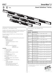
Product Overview<br />
Control<br />
Panel<br />
5-Pin DMX<br />
In/Out<br />
3-Pin DMX<br />
In/Out<br />
Safety<br />
Eye Bolt<br />
Fuse<br />
Power Out<br />
Power In<br />
Tilt<br />
Adjustment<br />
Knob<br />
Tilt<br />
Adjustment<br />
Knob<br />
March 3, 2010 -5- COLORado <strong>Batten</strong> <strong>72</strong> <strong>Tour</strong> User Manual <strong>Rev</strong>. <strong>01c</strong>
Setup<br />
3. Setup<br />
AC Power<br />
The COLORado <strong>Batten</strong> <strong>72</strong> <strong>Tour</strong> has an auto-ranging power supply that can work<br />
with an input voltage range of 100~240 VAC, 50/60 Hz.<br />
Make sure that you are connecting this product to the proper voltage, as per the<br />
specifications in this guide, the product’s user manual or on the product’s sticker.<br />
Always connect the COLORado <strong>Batten</strong> <strong>72</strong> <strong>Tour</strong> to a protected circuit with an<br />
appropriate electrical ground to avoid the risk of electrocution or fire.<br />
To determine the power requirements for the COLORado <strong>Batten</strong> <strong>72</strong> <strong>Tour</strong> see the<br />
label affixed to the side of the fixture. Alternatively, you may refer to the corresponding<br />
specifications chart in the Technical Information chapter of this manual.<br />
The listed current rating indicates the maximum current draw during normal operation.<br />
Please refer to the Sizing the Circuit Breakers section in the Appendix chapter of this<br />
manual.<br />
Never connect the COLORado <strong>Batten</strong> <strong>72</strong> <strong>Tour</strong> to a rheostat (variable resistor)<br />
or dimmer circuit, even if the rheostat or dimmer channel serves only as a 0 to<br />
100% switch.<br />
Power Linking<br />
AC Plug<br />
The COLORado <strong>Batten</strong> <strong>72</strong> <strong>Tour</strong> supports power linking for up to 13 other<br />
COLORado <strong>Batten</strong> <strong>72</strong> <strong>Tour</strong> fixtures at 120 VAC. Each COLORado <strong>Batten</strong> <strong>72</strong> <strong>Tour</strong><br />
has Neutrik POWERCON sockets for Power In and Power Out. Although the fixture<br />
comes with a power input cord, it comes with no power linking cord.<br />
The COLORado <strong>Batten</strong> <strong>72</strong> <strong>Tour</strong> comes with a power input cord terminated with a<br />
NEUTRIK® powerCON A connector on one end and an Edison plug on the other end<br />
(US market). If the power cord that came with your fixture has no plug or you need to<br />
change the Edison plug, use the table below to wire the new plug.<br />
Connection Wire (US) Wire (Europe) Screw Color<br />
AC Live Black Brown Yellow or Brass<br />
AC Neutral White Blue Silver<br />
AC Ground Green/Yellow Green/Yellow Green<br />
Fuse Replacement<br />
1) With a Phillips #2 head screwdriver, unscrew the fuse holder cap from its housing.<br />
2) Remove the blown fuse and replace it with a good fuse of the same type and rating.<br />
3) Screw the fuse holder cap back in its place and reconnect power.<br />
Make sure to disconnect the fixture’s power cord before replacing the blown<br />
fuse, and always replace it with a fuse of the same type and rating.<br />
The fuse is<br />
located inside<br />
this fuse holder<br />
bcLORado <strong>Batten</strong> <strong>72</strong> <strong>Tour</strong> User Manual <strong>Rev</strong>. <strong>01c</strong> -6- March 3, 2010
Setup<br />
Lens<br />
Replacement<br />
The COLORado <strong>Batten</strong> <strong>72</strong> <strong>Tour</strong> comes with the 15 lens assembly pre-installed from<br />
the factory. However, there is an optional lens kit (CL20x25x6) available as an<br />
accessory, which will provide a 25º x 6º beam.<br />
Follow the instructions below to to change or replace the LED lenses.<br />
a) Disconnect the fixture from the AC power before opening it.<br />
b) This procedure gives you direct access to the LEDs, which are very fragile.<br />
Use maximum care when handling the lenses over the LED assembly.<br />
The numbers in parenthesis in the procedure below correspond to the parts<br />
indicated in the Exploded View section of the Technical Information chapter.<br />
Procedure 1) Remove the four screws that hold either one of the side covers (10).<br />
2) Remove the side cover.<br />
3) Slide the clear cover (1) out of the way to expose the lens holders (2).<br />
4) Remove the eight screws that hold each of the three lens holders.<br />
5) Remove the lens holders from the fixture.<br />
6) Remove the existing lenses from the lens holders.<br />
7) Insert the new lenses in the lens holders, making sure that you have aligned them<br />
properly.<br />
8) <strong>Rev</strong>erse steps “1” to “5” to complete the lens replacement procedure.<br />
DMX Linking<br />
If you are using the COLORado <strong>Batten</strong> <strong>72</strong> <strong>Tour</strong> with a DMX controller, you can link<br />
them using a regular DMX serial connection. If using other DMX compatible fixtures<br />
with the COLORado <strong>Batten</strong> <strong>72</strong> <strong>Tour</strong>, it is possible to control them individually with a<br />
single DMX controller. It is also possible to run several DMX compatible fixtures<br />
synchronized without a DMX controller in a master/slave operating mode.<br />
If you are not familiar with the DMX standard, please refer to the DMX Primer and DMX<br />
Connectivity sections in the Appendix chapter of this manual.<br />
The DMX Channel Summary section in this chapter contains a brief description<br />
of what COLORado <strong>Batten</strong> <strong>72</strong> <strong>Tour</strong> features have a DMX channel assigned to<br />
them. The Operation chapter of this manual provides a detailed list of the<br />
COLORado <strong>Batten</strong> <strong>72</strong> <strong>Tour</strong> DMX channel assignments.<br />
DMX Modes<br />
Master/Slave<br />
Linking<br />
The COLORado <strong>Batten</strong> <strong>72</strong> <strong>Tour</strong> uses the standard DMX data connection for its DMX<br />
modes, TOUR, BLOCK1, BLOCK2, ARC1, ARC + D, ARC2, ARC2 + D, ARC + S, and<br />
HSV. Refer to the Introduction chapter for a brief description of these modes and the<br />
Operation Instructions chapter to learn how to configure the COLORado <strong>Batten</strong> <strong>72</strong><br />
<strong>Tour</strong> to work with these modes. The DMX Values section will give you detailed<br />
information regarding the above-mentioned DMX modes.<br />
The Master/Slave mode allows a COLORado <strong>Batten</strong> <strong>72</strong> <strong>Tour</strong> fixture (the master)<br />
running a preconfigured program to control several other COLORado <strong>Batten</strong> <strong>72</strong> <strong>Tour</strong><br />
fixtures (the slaves) without requiring a DMX controller. In this mode, all the slave<br />
fixtures will operate in unison with the master fixture.<br />
When in Master/Slave mode, the COLORado <strong>Batten</strong> <strong>72</strong> <strong>Tour</strong> units link to each other<br />
using the standard DMX connection.<br />
If you are not familiar with the Master/Slave connectivity, please refer to the DMX<br />
Primer and DMX Connectivity sections in the Appendix chapter of this manual.<br />
The Operation chapter of this manual provides detailed instructions on how to<br />
configure the Master and Slave units.<br />
ID Addressing<br />
The COLORado <strong>Batten</strong> <strong>72</strong> <strong>Tour</strong> uses the ID Addressing feature to increase the<br />
number of addressable fixtures in the same DMX universe when in the TOUR<br />
personality. Refer to the Operation chapter in this manual to learn in detail how to<br />
configure the COLORado 2 <strong>Tour</strong> fixtures when using ID Addressing.<br />
If you are not familiar with the various connection methods when using ID Addressing,<br />
you may refer to the ID Addressing section of the Appendix chapter in this manual.<br />
March 3, 2010 -7- COLORado <strong>Batten</strong> <strong>72</strong> <strong>Tour</strong> User Manual <strong>Rev</strong>. <strong>01c</strong>
Setup<br />
Mounting<br />
Orientation<br />
Rigging<br />
Read the safety notes at the beginning of this guide and follow their recommendations<br />
before mounting this product.<br />
Always mount this fixture in any safe position while making sure that there is adequate<br />
room around it for ventilation.<br />
Make sure to mount this fixture away from any flammable material as indicated in the<br />
Safety Notes.<br />
CHAUVET® recommends following the general guidelines below when mounting the<br />
COLORado <strong>Batten</strong> <strong>72</strong> <strong>Tour</strong>.<br />
• When selecting an installation location, consider ease of access to the product for<br />
operation, programming adjustments and routine maintenance.<br />
• Always mount this product making sure that there is adequate room around it for<br />
ventilation.<br />
• Do not expose this product to extreme temperature changes, rain or humidity.<br />
• If mounting this fixture overhead, make sure that the location where you are<br />
mounting it can support its weight. Please see the Technical Specifications section<br />
of this guide for the weight requirement of this product.<br />
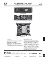
Procedure<br />
The COLORado <strong>Batten</strong> <strong>72</strong> <strong>Tour</strong> comes with two adjustable feet that double as<br />
hanging bracket to which you can attach “C” or “O” clamps. These feet also serve as<br />
floor or wall mount supports. You must supply your own “C” or “O” clamps and make<br />
sure that they are capable of supporting the weight of this fixture. You will have to use<br />
two mounting points per fixture.<br />
Clamp<br />
(Not<br />
provided)<br />
Safety<br />
Cable<br />
(Included)<br />
Clamp<br />
(Not<br />
provided)<br />
Product Mounting<br />
Diagram<br />
Overhead Mounting<br />
Floor Mounting<br />
bcLORado <strong>Batten</strong> <strong>72</strong> <strong>Tour</strong> User Manual <strong>Rev</strong>. <strong>01c</strong> -8- March 3, 2010
Operation<br />
4. Operation<br />
Control Panel<br />
Description<br />
Control Options<br />
Button Function CONTROL PANEL<br />
<br />
Exits from the current menu or<br />
function<br />
<br />
Enables the currently displayed<br />
menu or sets the currently selected<br />
value in to the current function<br />
<br />
Navigates upwards through the<br />
menu list and increases the<br />
numeric value when in a function.<br />
<br />
Navigates downwards through the<br />
menu list and decreases the<br />
numeric value when in a function<br />
You can set the COLORado <strong>Batten</strong> <strong>72</strong> <strong>Tour</strong> start address in the 001~512 DMX<br />
range. This allows for the control of up to 39 fixtures in the 13-channel TOUR<br />
personality. In addition, the ID address system allows you to assign up to 66 fixtures for<br />
each starting DMX address, thus multiplying the number of fixtures you can control<br />
within a single universe. You can access the fixture’s ID address system from channel<br />
12 when in the TOUR DMX personality.<br />
When programming live performances as well as cues that need to trigger on<br />
demand or on a time line, program no more than 10 fixtures on ID addressing per<br />
DMX channel. This is to remain within a one-second execution time.<br />
Programming<br />
DMX Personality<br />
DMX Control Without<br />
ID Addressing<br />
Carry out all the programming procedures indicated below from the control panel. Refer<br />
to the Menu Map on page 14 to learn how the menu options relate to each other.<br />
This setting allows the user to choose a particular DMX personality.<br />
1) Press repeatedly until PERSON shows, and press to accept.<br />
2) Use or to select the desired personality (TOUR, BLOCK1,<br />
BLOCK2, ARC1, AR1 + D, ARC2, AR2 + D, AR2 + S, or HSV).<br />
3) Press to accept.<br />
4) Press to return to the main level.<br />
In this mode, each unit will respond to a unique starting address from the DMX<br />
controller. All units with the same starting address will respond at unison.<br />
1) Select the TOUR personality as shown in DMX Personality.<br />
2) Set the running mode:<br />
a) Press repeatedly until RUN shows, and press to accept.<br />
b) Use or to select DMX, and press to accept.<br />
c) Press to return to the main level.<br />
3) Set the starting address:<br />
a) Press repeatedly until ADDRESS shows, and press to<br />
accept.<br />
b) Use or to select the starting address (001~512).<br />
c) Press to accept.<br />
d) Press to return to the main level.<br />
4) Deactivate ID Addressing in each fixture:<br />
a) Press repeatedly until SETTINGS shows, and press to<br />
accept.<br />
b) Use or to select ID ON/OFF, and press to accept.<br />
c) Use or to select OFF, and press to accept.<br />
d) Press twice to return to the main level.<br />
Make sure to deactivate ID Addressing in each fixture when using the TOUR<br />
personality. Otherwise, unintended results may occur if channel 11 is not set to<br />
“0”.<br />
March 3, 2010 -9- COLORado <strong>Batten</strong> <strong>72</strong> <strong>Tour</strong> User Manual <strong>Rev</strong>. <strong>01c</strong>
Operation<br />
Programming (Cont.)<br />
DMX Control With ID<br />
Addressing<br />
In this mode, the fixtures with the same DMX starting address will respond to the DMX<br />
controller based on the fixture’s individual ID address setting. If the user selects ID<br />
address “0”, all the fixtures with the same DMX address will respond in unison.<br />
Otherwise, each fixture will follow the control for its particular ID address.<br />
1) Repeat steps 1, 2 and 3 from DMX Control Without ID Addressing.<br />
2) Activate ID Addressing in each fixture:<br />
a) Press repeatedly until SETTINGS shows, and press to<br />
accept.<br />
b) Use or to select ID ON/OFF and press to accept.<br />
c) Use or to select ON, and press to accept.<br />
d) Press twice to return to the main level.<br />
Static Color<br />
The Static Color mode allows for permanent RGBWA color mixing without a DMX<br />
controller.<br />
1) Press repeatedly until STATIC shows, and press to accept.<br />
2) Use or to select the desired color (RED, GREEN, BLUE, WHITE or<br />
AMBER).<br />
3) Press to accept.<br />
4) Use or to select the desired color value (0~255).<br />
5) Press to accept.<br />
6) Repeat for the other colors.<br />
7) Use or to select STROBE, and press to accept.<br />
8) Use or to select the desired frequency (0~20).<br />
9) Press twice to return to the main level.<br />
Auto Programs<br />
Auto programs allow for dynamic RGBWA color mixing without a DMX controller.<br />
1) Press repeatedly until AUTO shows, and press to accept.<br />
2) Use or to select the desired auto program (AUTO 01~10 or<br />
CUSTOM 01~10).<br />
3) Press to accept.<br />
You cannot edit any of the auto programs (AUTO 01~10). However you can edit<br />
custom programs CUSTOM 01~10 (see Edit Customs).<br />
Edit Customs<br />
This setting allows the programming of up to 30 scenes for each of the 10 customizable<br />
programs, including colors and effects.<br />
1) Press repeatedly until EDIT shows, and press to accept.<br />
2) Use or to select the desired auto program (CUSTOM 01~10).<br />
3) Press to accept.<br />
4) Use or to select the desired scene (SCENE 01~30).<br />
5) Press to accept.<br />
6) Use or to select the desired color or effect (RED, GREEN, BLUE,<br />
WHITE, AMBER, STROBE, TIME or FADE) and press to accept.<br />
7) Use or to adjust the color or effect (000~255 for colors and timers,<br />
or 00~20 for Strobe) and press to accept.<br />
8) Repeat for the other colors or effects.<br />
9) Press to return to the SCENE level (step “4”).<br />
10) Repeat for the other scenes.<br />
11) Press to return to the main level once done.<br />
bcLORado <strong>Batten</strong> <strong>72</strong> <strong>Tour</strong> User Manual <strong>Rev</strong>. <strong>01c</strong> -10- March 3, 2010
Operation<br />
Programming (Cont.)<br />
Master/Slave<br />
The Master/Slave mode allows a group of COLORado <strong>Batten</strong> <strong>72</strong> <strong>Tour</strong> fixtures (the<br />
slaves) to execute simultaneously the same program, whether auto or custom, that<br />
another COLORado <strong>Batten</strong> <strong>72</strong> <strong>Tour</strong> fixture (the master) is executing, and without a<br />
DMX controller.<br />
1) Set the Master Unit:<br />
a) Set the running mode to DMX as explained in “DMX Control Without ID<br />
Addressing”<br />
b) Select an Auto program as explained in “Auto Programs”.<br />
2) Set the slave units:<br />
a) Press repeatedly until RUN shows, and press to accept.<br />
b) Use or to select SLAVE, and press to accept.<br />
c) Press to return to the main level.<br />
a) The fixture that runs an auto program automatically becomes the Master.<br />
b) Do not connect a DMX controller to the master or slave fixtures.<br />
Color Settings<br />
The COLOR setting determines how the COLORado <strong>Batten</strong> <strong>72</strong> <strong>Tour</strong> generates the<br />
white color based on various RGB settings.<br />
1) Press repeatedly until SETTINGS shows, and press to accept.<br />
2) Use or to select COLOR, and press to accept.<br />
3) Use or to select OFF, RGB TO W or UC.<br />
4) Press to accept.<br />
4) Press twice to exit to the main level.<br />
OFF = When RGB are all set to “255”, output is maximum.<br />
RGB TO W = When RGB are all set to “255”, output is the defined by the<br />
configured White color (see Whites Setting).<br />
UC = RGB are all set to the produce the same universal color<br />
Dimmer Curves<br />
This setting determines the output of the COLORado <strong>Batten</strong> <strong>72</strong> <strong>Tour</strong> based on the<br />
position of the Red, Green, Blue, White and Dimmer faders.<br />
1) Press repeatedly until SETTINGS shows, and press to accept.<br />
2) Use or to select DIMMER, and press to accept.<br />
3) Use or to select a dimmer curve (OFF, DIM1, DIM2, DIM3 or DIM4).<br />
4) Press to accept.<br />
When Dim is set to “OFF”, the output is proportional (linear) to the Dimmer and<br />
RGBW channel values.<br />
When Dim is set to “DIM1” through “DIM4”, the output follows the Dimmer and<br />
RGBW channel values based on the corresponding dimmer curve, being DIM1<br />
the fastest and DIM4 the slowest.<br />
Control Panel Lock<br />
This setting allows the user to activate or disable the control panel lock, which keeps<br />
non-authorized personnel from changing the fixture’s settings.<br />
1) Press repeatedly until KEYLOCK shows, and press to accept.<br />
2) Use or to select ON or OFF, and press to accept.<br />
When the control panel lock is active, the fixture will prompt the user to enter the<br />
password after 30 seconds of control panel inactivity or after turning on the<br />
fixture.<br />
After being prompted to enter the password:<br />
1) Press , , , and <br />
March 3, 2010 -11- COLORado <strong>Batten</strong> <strong>72</strong> <strong>Tour</strong> User Manual <strong>Rev</strong>. <strong>01c</strong>
Operation<br />
Programming (Cont.)<br />
Program Upload<br />
This option allows the user to copy the custom programs of one COLORado <strong>Batten</strong><br />
<strong>72</strong> <strong>Tour</strong> fixture onto other COLORado <strong>Batten</strong> <strong>72</strong> <strong>Tour</strong> fixtures by using the<br />
Master/Slave method<br />
1) Configure and connect the fixtures in a Master/Slave arrangement, where the<br />
master unit has the custom programs you want to transfer onto the slave units.<br />
2) At the master unit, press repeatedly until SETTINGS shows, and press<br />
to accept.<br />
3) Use or to select UPLOAD and press to accept.<br />
4) When prompted, enter the master access password as shown in Control Panel<br />
Lock.<br />
5) When SEND shows, press to start the upload.<br />
6) Wait for the upload process to finish before disconnecting the fixtures.<br />
During and after the upload, the master and slave units will visually indicate the<br />
status of the process, as follows:<br />
Yellow means that the upload is running.<br />
Red means that the upload failed due to an error.<br />
Green means that the upload completed successfully.<br />
Reset<br />
This setting allows the user to reset the COLORado <strong>Batten</strong> <strong>72</strong> <strong>Tour</strong> fixture to its<br />
default values, including the custom programs.<br />
1) Press repeatedly until SETTINGS shows, and press to accept.<br />
2) Use or to select RESET, and press to accept.<br />
3) When prompted, enter the master access password as shown in Control Panel<br />
Lock.<br />
4) Wait for the reset process to finish.<br />
Default Values Parameter Default Value Parameter Default Value<br />
STATIC 000 DIMMER DIM4<br />
ADDRESS 001 COLOR OFF<br />
RUN DMX EDIT 000<br />
PERSON TOUR FANS AUTO<br />
ID 001 KEYLOCK OFF<br />
ID ON/OFF<br />
ON<br />
Whites Setting<br />
This setting allows the user to select and edit the temperature of the white colors used<br />
in channel 7 (Macros) when in the TOUR mode. It also allows the user to define the<br />
maximum RGB values when RGB to White is active.<br />
1) Press repeatedly until CALIB shows, and press to accept.<br />
2) Use or to select a white color (WHITE 1~11) or RGB TO W.<br />
3) Press to accept.<br />
4) Use or to select a color (RED, GREEN, BLUE, WHITE, .AMBER).<br />
5) Press to accept.<br />
6) Use or to select a color value (0~255).<br />
7) Repeat for the other colors.<br />
8) Press to exit once done.<br />
When selecting RGB TO W, you will only be able to define the values of RED,<br />
GREEN and BLUE.<br />
The values of RED, GREEN and BLUE configured from CALIB > RGB TO W will<br />
define the color temperature shown when the RGB faders are set to “255” if<br />
COLOR > RGB TO W is active.<br />
bcLORado <strong>Batten</strong> <strong>72</strong> <strong>Tour</strong> User Manual <strong>Rev</strong>. <strong>01c</strong> -12- March 3, 2010
Operation<br />
Programming (Cont.)<br />
Fan Setting<br />
1) Press repeatedly until FANS shows, and press to accept.<br />
2) Use or to select a setting (OFF, LOW, NORMAL, HIGH or AUTO).<br />
3) Press to exit once done.<br />
a) When in AUTO, the fan speed automatically changes so the fixture’s<br />
temperature does not exceed the limit.<br />
b) When in the other settings, the fan speed follow the predefine values.<br />
c) The internal controller will override any manual setting if the internal<br />
temperature rises above a certain level.<br />
TOUR Notes<br />
Master Dimmer<br />
Red, Green, Blue<br />
White and Amber<br />
Color Selection<br />
Color Macros<br />
These notes intent to clarify the way the TOUR DMX personality works.<br />
• Channel 1 controls the intensity of the currently projected color.<br />
• When the slider is at the highest position (255) the intensity of the output is at its<br />
maximum<br />
• Channels, 2, 3, 4, 5 and 6 control the intensity ratio of each of the Red, Green, Blue,<br />
White and LEDs<br />
• When the slider is at the highest position (255) the intensity of each color is at its<br />
maximum if SETTINGS > COLOR is OFF.<br />
• You can combine channels, 2, 3, 4,5 and 6 to create over one trillion colors<br />
• Channel 7 selects the required Color Macro<br />
• Channel 7 has priority over channels 2, 3, 4 and 5<br />
• Channel 1 controls the intensity of the Color Macro<br />
Strobe • Channel 8 controls the strobe of channels 2~6<br />
ID Address Selection<br />
Auto<br />
Dimmer Speed<br />
• Channel 12 selects the target ID address<br />
• Each independent DMX address may have up to 66 independent ID addresses<br />
• An ID address of 0 will activate all ID address locations<br />
• Channel 9 selects the preset Auto programs AUTO 01~10 or the custom Auto<br />
programs CUSTOM 01~10<br />
• When activating the custom Auto programs CUSTOM 01~10, it is possible to control<br />
the Step Time and Fade Time using channels 2 and 3 respectively<br />
• Channel 9 has priority over channels 2, 3, 4, 5, 6, 7 and 8.<br />
• Channel 10 is for selecting the dimmer mode and speed. When DIMMER is set to<br />
OFF, RGBW and Master Dimmer are linear. Otherwise, DIM1 is the fastest dimmer<br />
curve, while DIM4 is the slowest.<br />
March 3, 2010 -13- COLORado <strong>Batten</strong> <strong>72</strong> <strong>Tour</strong> User Manual <strong>Rev</strong>. <strong>01c</strong>
Operation<br />
COLORado <strong>Batten</strong> <strong>72</strong> <strong>Tour</strong> Menu Map<br />
bcLORado <strong>Batten</strong> <strong>72</strong> <strong>Tour</strong> User Manual <strong>Rev</strong>. <strong>01c</strong> -14- March 3, 2010
Operation<br />
DMX Values<br />
TOUR Channel Function Value Percent/Setting<br />
1 Dimmer 000 255 0~100%<br />
2 Red 000 255 0~100% (or Step Time if Custom 01~10 in Ch. 9 is active)<br />
3 Green 000 255 0~100% (or Fade Time if Custom 01~10 in Ch. 9 is active)<br />
4 Blue 000 255 0~100%<br />
5 White 000 255 0~100%<br />
6 Amber 000 255 0~100%<br />
7<br />
Color Macro +<br />
White Balance<br />
8 Strobe<br />
9<br />
Auto + Custom<br />
Programs +<br />
Fan Control<br />
000 010<br />
011 030<br />
031 050<br />
051 070<br />
071 090<br />
091 110<br />
111 130<br />
131 150<br />
151 170<br />
171 200<br />
201 205<br />
206 210<br />
211 215<br />
216 220<br />
221 225<br />
226 230<br />
231 235<br />
236 240<br />
241 245<br />
246 250<br />
251 255<br />
000 009<br />
010 255<br />
000 010<br />
011 020<br />
021 030<br />
031 040<br />
041 050<br />
051 060<br />
061 070<br />
071 080<br />
081 090<br />
091 100<br />
101 110<br />
111 120<br />
121 130<br />
131 140<br />
141 150<br />
151 160<br />
161 170<br />
171 180<br />
181 190<br />
191 200<br />
201 210<br />
211 220<br />
221 230<br />
231 240<br />
241 250<br />
251 255<br />
10 Auto Speed 000 255 0~100%<br />
11 Dimmer Speed<br />
000 009<br />
010 029<br />
030 069<br />
070 129<br />
130 189<br />
190 255<br />
No function<br />
R: 100% / G: Up / B: 0%<br />
R: Down / G: 100% / B: 0%<br />
R: 0% / G: 100% / B: Up<br />
R: 0% / G: Down / B: 100%<br />
R: Up / G: 0% / B: 100%<br />
R: 100% / G: 0% / B: Down<br />
R: 100% / G: Up / B: Up<br />
R: Down / G: Down / B: 100%<br />
R: 100% / G: 100% / B: 100% / W: 100%<br />
White 1: 3200 K<br />
White 2: 3400 K<br />
White 3: 4200 K<br />
White 4: 4900 K<br />
White 5: 5600 K<br />
White 6: 5900 K<br />
White 7: 6500 K<br />
White 8: <strong>72</strong>00 K<br />
White 9: 8000 K<br />
White 10: 8500 K<br />
White 11: 10,000 K<br />
No function<br />
1~20 Hz<br />
No function<br />
Fans Off (Stay 3 s)<br />
Fans Low (Stay 3 s)<br />
Fans Normal (Stay 3 s)<br />
Fans High (Stay 3 s)<br />
Fans Auto (Stay 3 s)<br />
Auto 1<br />
Auto 2<br />
Auto 3<br />
Auto 4<br />
Auto 5<br />
Auto 6<br />
Auto 7<br />
Auto 8<br />
Auto 9<br />
Auto 10<br />
Custom 1<br />
Custom 2<br />
Custom 3<br />
Custom 4<br />
Custom 5<br />
Custom 6<br />
Custom 7<br />
Custom 8<br />
Custom 9<br />
Custom 10<br />
Dimmer speed as per Control Panel<br />
Linear dimmer<br />
Non-linear dimmer 1 (fastest)<br />
Non-linear dimmer 2<br />
Non-linear dimmer 3<br />
Non-linear dimmer 4 (slowest)<br />
March 3, 2010 -15- COLORado <strong>Batten</strong> <strong>72</strong> <strong>Tour</strong> User Manual <strong>Rev</strong>. <strong>01c</strong>
Operation<br />
TOUR (Cont.) Channel Function Value Setting Value Setting Value Setting<br />
12 ID Address<br />
000 009<br />
010 019<br />
020 029<br />
030 039<br />
040 049<br />
050 059<br />
060 069<br />
070 079<br />
080 089<br />
090 099<br />
100 109<br />
110 119<br />
120 129<br />
130 139<br />
140 149<br />
150 159<br />
160 169<br />
170 179<br />
180 189<br />
190 199<br />
200 209<br />
210<br />
211<br />
All IDs<br />
ID 1<br />
ID 2<br />
ID 3<br />
ID 4<br />
ID 5<br />
ID 6<br />
ID 7<br />
ID 8<br />
ID 9<br />
ID 10<br />
ID 11<br />
ID 12<br />
ID 13<br />
ID 14<br />
ID 15<br />
ID 16<br />
ID 17<br />
ID 18<br />
ID 19<br />
ID 20<br />
ID 21<br />
ID 22<br />
Channel Function Value Percent/Setting<br />
13 Block Selection<br />
000 004<br />
005 034<br />
035 064<br />
065 094<br />
095 124<br />
125 154<br />
155 184<br />
185 214<br />
215 255<br />
Blocks 1, 2 & 3<br />
Block 1<br />
Block 2<br />
Block 3<br />
Blocks 1 & 2<br />
Blocks 2 & 3<br />
Blocks 1 & 3<br />
Blocks 1, 2 & 3<br />
No Function<br />
BLOCK1 Channel Function Value Percent/Setting<br />
1 Block 1 - Red 000 255 0~100%<br />
2 Block 1 - Green 000 255 0~100%<br />
3 Block 1 - Blue 000 255 0~100%<br />
4 Block 2 - Red 000 255 0~100%<br />
5 Block 2 - Green 000 255 0~100%<br />
6 Block 2 - Blue 000 255 0~100%<br />
7 Block 3 - Red 000 255 0~100%<br />
8 Block 3 - Green 000 255 0~100%<br />
9 Block 3 - Blue 000 255 0~100%<br />
BLOCK1 Channel Function Value Percent/Setting<br />
1 Block 1 - Red 000 255 0~100%<br />
2 Block 1 - Green 000 255 0~100%<br />
3 Block 1 - Blue 000 255 0~100%<br />
4 Block 1 – White 000 255 0~100%<br />
5 Block 1 - Amber 000 255 0~100%<br />
6 Block 2 - Red 000 255 0~100%<br />
7 Block 2 - Green 000 255 0~100%<br />
8 Block 2 - Blue 000 255 0~100%<br />
9 Block 2 – White 000 255 0~100%<br />
10 Block 2 - Amber 000 255 0~100%<br />
11 Block 3 - Red 000 255 0~100%<br />
12 Block 3 - Green 000 255 0~100%<br />
13 Block 3 - Blue 000 255 0~100%<br />
14 Block 3 - White 000 255 0~100%<br />
15 Block 3 - Amber 000 255 0~100%<br />
212<br />
213<br />
214<br />
215<br />
216<br />
217<br />
218<br />
219<br />
220<br />
221<br />
222<br />
223<br />
224<br />
225<br />
226<br />
227<br />
228<br />
229<br />
230<br />
231<br />
232<br />
233<br />
234<br />
ID 23<br />
ID 24<br />
ID 25<br />
ID 26<br />
ID 27<br />
ID 28<br />
ID 29<br />
ID 30<br />
ID 31<br />
ID 32<br />
ID 33<br />
ID 34<br />
ID 35<br />
ID 36<br />
ID 37<br />
ID 38<br />
ID 39<br />
ID 40<br />
ID 41<br />
ID 42<br />
ID 43<br />
ID 44<br />
ID 45<br />
235<br />
236<br />
237<br />
238<br />
239<br />
240<br />
241<br />
242<br />
243<br />
244<br />
245<br />
246<br />
247<br />
248<br />
249<br />
250<br />
251<br />
252<br />
253<br />
254<br />
255<br />
ID 46<br />
ID 47<br />
ID 48<br />
ID 49<br />
ID 50<br />
ID 51<br />
ID 52<br />
ID 53<br />
ID 54<br />
ID 55<br />
ID 56<br />
ID 57<br />
ID 58<br />
ID 59<br />
ID 60<br />
ID 61<br />
ID 62<br />
ID 63<br />
ID 64<br />
ID 65<br />
ID 66<br />
bcLORado <strong>Batten</strong> <strong>72</strong> <strong>Tour</strong> User Manual <strong>Rev</strong>. <strong>01c</strong> -16- March 3, 2010
Operation<br />
ARC1 Channel Function Value Percent/Setting<br />
1 Red 000 255 0~100%<br />
2 Green 000 255 0~100%<br />
3 Blue 000 255 0~100%<br />
ARC1 + D Channel Function Value Percent/Setting<br />
1 Master Dimmer 000 255 0~100%<br />
2 Red 000 255 0~100%<br />
3 Green 000 255 0~100%<br />
4 Blue 000 255 0~100%<br />
ARC2 Channel Function Value Percent/Setting<br />
1 Red 000 255 0~100%<br />
2 Green 000 255 0~100%<br />
3 Blue 000 255 0~100%<br />
4 White 000 255 0~100%<br />
5 Amber 000 255 0~100%<br />
ARC2 + D Channel Function Value Percent/Setting<br />
1 Master Dimmer 000 255 0~100%<br />
2 Red 000 255 0~100%<br />
3 Green 000 255 0~100%<br />
4 Blue 000 255 0~100%<br />
5 White 000 255 0~100%<br />
6 Amber 000 255 0~100%<br />
ARC2 + S Channel Function Value Percent/Setting<br />
1 Master Dimmer 000 255 0~100%<br />
2 Red 000 255 0~100%<br />
3 Green 000 255 0~100%<br />
4 Blue 000 255 0~100%<br />
5 White 000 255 0~100%<br />
6 Amber 000 255 0~100%<br />
7 Strobe<br />
000 010 No function<br />
011 255 0~20 Hz<br />
HSV Channel Function Value Percent/Setting<br />
1 Hue 000 255 0~100%<br />
2 Saturation 000 255 0~100%<br />
3 Value 000 255 0~100%<br />
In HSV mode, Hue refers to the visible light, such as red, yellow, and cyan, etc. Saturation<br />
is the dominance of hue in the color; when saturation is at 100%, the color is at its purest.<br />
Value is the color’s brightness; when value is at 100%, the color is at its brightest.<br />
March 3, 2010 -17- COLORado <strong>Batten</strong> <strong>72</strong> <strong>Tour</strong> User Manual <strong>Rev</strong>. <strong>01c</strong>
Technical Information<br />
5. Technical Information<br />
General<br />
Maintenance<br />
To maintain optimum performance and minimize wear, the user should clean the<br />
fixtures frequently. Usage and environment are contributing factors in determining the<br />
cleaning frequency. As a rule, the user should clean the fixtures at least twice a<br />
month. Dust build up reduces light output performance and can cause overheating.<br />
This can lead to reduced light source life and increased mechanical wear.<br />
For fixtures containing external optical lenses, the user should clean them periodically<br />
to optimize light output. The cleaning frequency depends on the environment in which<br />
the fixture operates. Damp, smoky or particularly dirty surrounding can cause greater<br />
accumulation of dirt on the unit’s optics. Even in the cleanest type of surroundings, the<br />
user should clean the external optics at least once every 30 days. CHAUVET®<br />
recommends cleaning the fixture’s external optics with a soft cloth using normal glass<br />
cleaning fluid.<br />
To clean a fixture, follow the below recommendations:<br />
• Unplug the fixture from power.<br />
• Wait until the fixture is cold.<br />
• Use a vacuum (or dry compressed air) and a soft brush to remove dust collected<br />
on the external vents and reachable internal components.<br />
• Clean all external optics and glass surfaces with a mild solution of glass cleaner or<br />
isopropyl alcohol, and a soft, lint free cotton cloth or a lens cleaning tissue.<br />
• Apply the solution directly to the cloth or tissue and drag any dirt and grime to the<br />
outside of the lens.<br />
• Gently polish the external glass surfaces until they are free of haze and lint.<br />
• When cleaning movable mirrors, to avoid scratching or damaging their surface,<br />
minimize the contact with the mirror surface to a minimum.<br />
Always dry the external optics and glass surfaces carefully after cleaning them.<br />
Never spin a fan using compressed air.<br />
bcLORado <strong>Batten</strong> <strong>72</strong> <strong>Tour</strong> User Manual <strong>Rev</strong>. <strong>01c</strong> -18- March 3, 2010
Technical Information<br />
COLORado <strong>Batten</strong> <strong>72</strong> <strong>Tour</strong> Troubleshooting Guide<br />
Symptom Cause(s) Action(s)<br />
General low light intensity<br />
Dirty lens assembly<br />
Clean the fixture regularly<br />
Misaligned lens assembly<br />
Install lens assembly properly<br />
A single LED (R, G, B, W Faulty LED<br />
or A) does not illuminate Faulty LED board<br />
Replace the LED board<br />
A group of LEDs (R, G, B,<br />
Faulty LED<br />
W or A) does not<br />
Faulty LED board<br />
Replace the LED board<br />
illuminate<br />
Faulty LED driver<br />
Replace the LED Driver board<br />
Faulty LED board<br />
Replace the LED board<br />
None of the LEDs in a<br />
module are illuminating<br />
Faulty LED Driver board<br />
Replace the LED Driver board<br />
Faulty Display/Main board<br />
Replace the Display/Main board<br />
Breaker/Fuse keeps Excessive circuit load<br />
Check total load placed on the electrical circuit<br />
blowing<br />
Short circuit along the power wires Check for a short in the electrical wiring<br />
No power<br />
Check for power on power outlet<br />
Fixture does not power up<br />
Loose or damaged power cord<br />
Check power cord<br />
Blown fuse<br />
Replace fuse<br />
Faulty internal power supply<br />
Replace internal power supply<br />
Wrong DMX addressing<br />
Check Control Panel and unit addressing<br />
Damaged DMX cables<br />
Check DMX cables<br />
Fixture does not respond Wrong polarity on the controller<br />
Check polarity switch settings on the controller<br />
to DMX<br />
Loose DMX cables<br />
Check cable connections<br />
Faulty DMX interface<br />
Replace the Display/Main board<br />
Faulty Display/Main board<br />
Replace the Display/Main board<br />
Non DMX cables<br />
Use only DMX compatible cables<br />
Bouncing signals<br />
Install terminator as suggested<br />
DMX signal problems<br />
Long cable / low level signal<br />
Install an optically coupled DMX splitter right after<br />
the fixture with the strong signal<br />
Too many fixtures<br />
Install an optically coupled DMX splitter after unit<br />
#32 or before<br />
Interference from AC wires<br />
Keep DMX cables separated from power cables or<br />
fluorescent/black lights<br />
If you still experience technical problems after trying the above solutions, contact<br />
CHAUVET® Technical Support.<br />
March 3, 2010 -19- COLORado <strong>Batten</strong> <strong>72</strong> <strong>Tour</strong> User Manual <strong>Rev</strong>. <strong>01c</strong>
Technical Information<br />
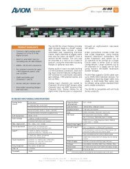
Exploded View<br />
Item Description Part Code<br />
1 Clear front plate P300-CB<strong>72</strong>TCP<br />
2 Complete lens set P115-CB<strong>72</strong>T<br />
3 LED board A P222-CB<strong>72</strong>TA<br />
4 LED board B P222-CB<strong>72</strong>TB<br />
5 Heat sink board P222-CB<strong>72</strong>THS<br />
6 Power supply P142-CB<strong>72</strong>T<br />
7 Display board P173-CB<strong>72</strong>T<br />
8 LED driver board P1<strong>72</strong>-CB<strong>72</strong>T<br />
9 Fan P131-24V40X20<br />
10 Side cover P300-CB<strong>72</strong>TS<br />
11 Power output socket (white) P136-NAC3FCB<br />
12 Power input socket (blue) P136-NAC3MPA<br />
13 Fuse holder P144-CB<strong>72</strong>T<br />
14 Support bracket P125-CB<strong>72</strong>T<br />
bcLORado <strong>Batten</strong> <strong>72</strong> <strong>Tour</strong> User Manual <strong>Rev</strong>. <strong>01c</strong> -20- March 3, 2010
Technical Information<br />
Photometric Data<br />
March 3, 2010 -21- COLORado <strong>Batten</strong> <strong>72</strong> <strong>Tour</strong> User Manual <strong>Rev</strong>. <strong>01c</strong>
Technical Information<br />
Returns<br />
Procedure<br />
The user must send the merchandise prepaid, in the original box, and with its original<br />
packing and accessories. CHAUVET® will not issue call tags.<br />
Call CHAUVET® and request a Return Merchandise Authorization Number (RMA #)<br />
before shipping the fixture. Be prepared to provide the model number, serial number<br />
and a brief description of the cause for the return.<br />
The user must clearly label the package with a Return Merchandise Authorization<br />
Number (RMA #). CHAUVET® will refuse any product returned without an RMA #.<br />
DO NOT write the RMA # directly on the box. Instead, write it on a properly<br />
affixed label.<br />
Once you are given an RMA #, please include the following information on a piece of<br />
paper inside the box:<br />
• Your name<br />
• Your address<br />
• Your phone number<br />
• The RMA #<br />
• A brief description of the symptoms<br />
Be sure to pack the fixture properly. Any shipping damage resulting from inadequate<br />
packaging will be the customer’s responsibility. As a suggestion, proper UPS packing<br />
or double-boxing is always a safe method to use.<br />
CHAUVET® reserves the right to use its own discretion to repair or replace<br />
returned product(s).<br />
Claims<br />
The shipper is responsible for any damage incurred during shipping. Therefore, if the<br />
merchandize appears damaged due to shipping, the customer's must submit the<br />
damage report and any related claims with the carrier, not CHAUVET®. The customer<br />
must submit the report upon reception of the damaged merchandise. Failure to do so in<br />
a timely manner may invalidate the customer’s claim with the carrier.<br />
For other issues such as missing components or parts, damage not related to shipping,<br />
or concealed damage, the customer must made claims to CHAUVET® within seven (7)<br />
days of receiving the merchandise.<br />
Contact Us<br />
World Wide<br />
General Information<br />
Technical Support<br />
World Wide Web<br />
CHAUVET®<br />
3000 North 29th Court<br />
Hollywood, FL 33020<br />
Voice: (954) 929-1115<br />
Fax: (954).929-5560<br />
Toll free: (800) 762-1084<br />
Voice: (954) 929-1115 (Press 4)<br />
Fax: (954) 929-5560 (Attention: Service)<br />
www.chauvetlighting.com<br />
bcLORado <strong>Batten</strong> <strong>72</strong> <strong>Tour</strong> User Manual <strong>Rev</strong>. <strong>01c</strong> -22- March 3, 2010
Technical Information<br />
Technical Specifications<br />
Weight & Dimensions<br />
Length .............................................................................................................................. 38.9 in (989 mm)<br />
Width.................................................................................................................................... 3.0 in (77 mm)<br />
Height ................................................................................................................................ 6.1 in (156 mm)<br />
Weight................................................................................................................................. 9.8 lbs (4.4 kg)<br />
Power<br />
Auto-ranging ........................................................................................................ 100~240 VAC, 50/60 Hz<br />
Power Consumption @ 120 V ............................................................................................. <strong>72</strong> W (1.067 A)<br />
Power Consumption @ 230 V ............................................................................................. 71 W (0.568 A)<br />
Inrush Current .............................................................................................. 0.4 A @ 120 V, 0.8 A@ 230 V<br />
Power Linking .......................................................................................................... 13 units max @ 120 V<br />
Power Connectors ................................................................................ NEUTRIK® powerCON connectors<br />
<strong>Light</strong> Source<br />
Type ............................................................................................................ 1 W, 350 mA 50,000 hrs LEDs<br />
Configuration ................................................. <strong>72</strong> LEDs (18 Red, 18 Green, 18 Blue, 9 White and 9 Amber)<br />
Photometrics<br />
Installed optics: ..................................................................................................................................... 30º<br />
Beam angle: ....................................................................................................................................... 40.1º<br />
Field angle: ........................................................................................................................................ 54.8º<br />
Illuminance: ....................................................................................................................... 1,300 lux @ 2 m<br />
Thermal<br />
Maximum ambient temperature ............................................................................................ 104° F (40° C)<br />
Control & Programming<br />
Data input ..................................................................................... Locking 3-pin or 5-pin XLR male socket<br />
Data output ................................................................................ Locking 3-pin or 5-pin XLR female socket<br />
Data pin configuration ................................................................................. Pin 1 shield, pin 2 (-), pin 3 (+)<br />
Protocols ........................................................................................................................ USITT DMX512-A<br />
DMX Channels ....................................................................................................... 3, 4, 5, 6, 7, 9, 13 or 15<br />
Ordering Information<br />
COLORado <strong>Batten</strong> <strong>72</strong> <strong>Tour</strong> ..................................................................... COLORADOBATTEN<strong>72</strong>TOUR<br />
Warranty Information<br />
Warranty ................................................................................................................. 2-year limited warranty<br />
March 3, 2010 -23- COLORado <strong>Batten</strong> <strong>72</strong> <strong>Tour</strong> User Manual <strong>Rev</strong>. <strong>01c</strong>
Appendix<br />
6. Appendix<br />
DMX Primer<br />
The Physical Medium<br />
The DMX protocol (USITT DMX512-A) is a networking protocol that enables a universal<br />
DMX controller device to control the features of multiple DMX compatible fixtures,<br />
whether par cans, wash lights, moving heads, followspots, foggers, proprietary fixture<br />
controllers, etc.<br />
As any other networking protocol, the USITT DMX512-A describes the physical<br />
medium, the signals and the functions they control.<br />
The DMX controller connects to it associated DMX compatible fixtures using a DMX<br />
connection. This connection consists of a series of jumps between the DMX controller<br />
and the various DMX compatible fixtures, also known as a daisy chain connection. In<br />
this type of connection, the DATA OUT of one fixture or the DMX controller connects to<br />
the DATA IN of the next fixture, and so on.<br />
Each DMX fixture links to the previous and next DMX fixture or controller using a DMX<br />
cable. This type of cable consists of a section of shielded, two-conductor twisted pair<br />
cable with one 3-pin XLR male connector on one end and a 3-pin XLR female<br />
connector on the other end. The XLR connectors pin-out is as follows: pin 1 is the<br />
Common (shield), pin 2 is Signal Negative (S-) and pin 3 is Signal Positive (S+).<br />
The Signals<br />
The Functions<br />
DMX<br />
Configuration<br />
Personalities<br />
Starting<br />
Address<br />
The DMX signal stream is unidirectional, from the DMX controller to the DMX<br />
compatible fixtures. These signals conform to the EIA-485 standard.<br />
The stream of DMX signals consists of 512 individual, sequential channels that form a<br />
frame. The DMX controller constantly sends frames of DMX signals to the DMX<br />
connection, even if not all of the 512 channels are in use. Because of this constant<br />
transmission method, there can be only one DMX controller in a DMX connection.<br />
Otherwise, the DMX signals sent by one controller would interfere with the signals sent<br />
by the other controller(s).<br />
Each DMX channel can have any unitary value in the 000~255 range. Each DMX<br />
compatible fixture uses as many consecutive DMX channels as features the user can<br />
control. The sequential numbers assigned to each DMX channel (1~512) are also<br />
known as DMX addresses.<br />
The function each DMX channel has and the results of assigning a value to each<br />
depend on each controlled fixture. Some fixtures only use a single DMX channel, while<br />
others may require 15 or more DMX channels to control all their functions.<br />
The DMX fixture configuration consists in determining how many channels each fixture<br />
will need as well as assigning the corresponding DMX channels to each fixture in order<br />
to size correctly the DMX controller.<br />
Most DMX fixtures use multiple personalities, each of them requiring a different number<br />
of channels, depending on the number of features it enables. The number of DMX<br />
channels used by a fixture may vary from only one (usually the general dimmer control)<br />
to 15 or more, as mentioned above.<br />
When the job does not require using all the fixture’s capabilities, the user can select a<br />
more basic personality (less channels), thus allowing the DMX controller to<br />
accommodate more DMX fixtures.<br />
For the DMX controller to control each DMX fixture, the user must first configure each<br />
fixture’s personality. This will determine the number of required channels to control the<br />
fixture. Each channel will have a DMX address assigned to it. However, since assigning<br />
a particular DMX address to each channel is impractical, the user will only need to<br />
configure on each fixture the DMX address that corresponds to the fixture’s Channel 1.<br />
This is the fixture’s starting address. The fixture will automatically assign the other<br />
channels to the subsequent DMX addresses.<br />
Once this assignment is complete, and based on the number of channels it uses, the<br />
fixture will respond to the DMX signals sent to the range of DMX channels that begins<br />
with the starting address.<br />
For example, a fixture that uses six DMX channels and whose starting address is 100,<br />
will accept DMX data sent by the DMX controller to channels 100, 101, 102, 103, 104,<br />
and 105.<br />
bcLORado <strong>Batten</strong> <strong>72</strong> <strong>Tour</strong> User Manual <strong>Rev</strong>. <strong>01c</strong> -24- March 3, 2010
Appendix<br />
DMX Configuration (Cont.)<br />
Assigning Addresses<br />
DMX Universes<br />
DMX<br />
Connectivity<br />
Fixture<br />
Location<br />
Number of<br />
Fixtures<br />
The user must carefully assign the starting addresses for each individual fixture to<br />
avoid DMX channel overlapping. If the DMX channels do overlap, the affected fixtures<br />
could operate erratically.<br />
However, the user may decide to configure two or more similar fixtures with the same<br />
personality and starting address. In this case, all the fixtures with the same starting<br />
address will operate at unison.<br />
A DMX universe is the set of DMX compatible fixtures connected to the same DMX<br />
daisy chain, which are receiving DMX data from the same DMX controller using the<br />
same set of 512 DMX channels.<br />
Although in most cases an installation will consist of only one DMX universe, it could be<br />
necessary to define two or more universes because of constrains imposed by the<br />
distance or the number of features.<br />
Most DMX controllers support only one universe, although some DMX controllers may<br />
support two or more universes. Each universe will have its own separated DMX daisy<br />
chain. A DMX compatible fixture can only be part of a single DMX universe.<br />
Connecting the DMX fixtures to a DMX controller in small to medium installations is<br />
usually a rather simple operation that requires a minimum of tools and some planning<br />
(not including the actual fixture rigging and configuration).<br />
However, in large installations it may be necessary to plan carefully the position and<br />
cabling of each fixture to avoid unexpected problems.<br />
The order in which the fixtures connect to the DMX controller is not important and it has<br />
no effect on how a controller communicates to each fixture. However, the user should<br />
always define a physical location for the fixtures that provides for the easiest and most<br />
direct cabling to the controller and other fixtures.<br />
When using a DMX controller, the combined number of channels required by all the<br />
fixtures on the serial data link determines the number of fixtures the DMX controller has<br />
to support. Conversely, the number of onboard sliders, page buttons and fixture buttons<br />
limits the number of discrete DMX channels a DMX controller can support.<br />
To comply with the EIA-485 standard, which is the base for the USITT<br />
DMX512-A protocol, do not connect more than 32 fixtures without using a DMX<br />
optically-isolated splitter. Doing otherwise may result in deterioration of the<br />
digital DMX signal.<br />
DMX Data<br />
Cabling<br />
You must use DMX compliant data cables to link two or more DMX compatible fixtures.<br />
You may purchase CHAUVET® certified DMX cables directly from a dealer/distributor<br />
or construct your own cable.<br />
USITT recommends limiting the total length of the DMX cable (from the first<br />
fixture/controller to the last fixture) to 300~455 m (985~1,500 ft).<br />
Making your Own<br />
DMX Cable<br />
If you choose to create your own DMX cable, make sure to use data-grade cables that<br />
can carry a high frequency signal and are less prone to electromagnetic interference.<br />
Use a Belden© 9841 or equivalent cable, which meets the specifications for EIA RS-<br />
485 applications.<br />
Do not use standard microphone cables for DMX applications because they<br />
cannot transmit DMX data reliably over long distances.<br />
DMX Cable<br />
Characteristics<br />
The DMX data cable must have the following characteristics:<br />
Type:<br />
shielded, 2-conductor twisted pair<br />
Maximum capacitance between conductors:<br />
30 pF/ft<br />
Maximum capacitance between conductor and shield:<br />
55 pF/ft<br />
Maximum resistance:<br />
20 ohms/1000 ft<br />
Nominal impedance:<br />
100~140 ohms<br />
March 3, 2010 -25- COLORado <strong>Batten</strong> <strong>72</strong> <strong>Tour</strong> User Manual <strong>Rev</strong>. <strong>01c</strong>
Appendix<br />
DMX Connectivity (Cont.)<br />
DMX Cable<br />
Connectors<br />
Each DMX cable must have a male, 3-pin XLR connector on one end and a female, 3-<br />
pin XLR connector on the other end.<br />
DMX Connector Configuration<br />
To DMX Input<br />
(Female)<br />
1<br />
3<br />
2<br />
Common<br />
DMX +<br />
DMX -<br />
To DMX Output<br />
(Male)<br />
1<br />
3<br />
2<br />
To avoid signal transmission problems and interference, it is always advisable to<br />
connect a DMX signal terminator, as seen below.<br />
1<br />
3<br />
2<br />
120 ohm, ¼ W<br />
resistor between<br />
pin 2 (DMX -) and<br />
pin 3 (DMX +) on<br />
the output of the<br />
last fixture.<br />
Test all DMX cables with an ohmmeter to verify their correct polarity and to make<br />
sure that there are no short-circuits between any of the pins, or between any pin<br />
and ground.<br />
If the Common wire (shield) touched the chassis ground, a ground loop could<br />
form, which may cause the fixture to perform erratically.<br />
3-Pin to 5-Pin<br />
Conversion Chart<br />
DMX Connection<br />
If you use a DMX controller or fixture with a 5-pin DMX connector, you will need to use<br />
a 5-pin to 3-pin adapter. The chart below details a proper cable conversion.<br />
3-Pin to 5-Pin Conversion Chart<br />
Conductor 3-Pin Female (Output) 5-Pin Male (Input)<br />
Ground/Shield Pin 1 Pin 1<br />
Negative (-) signal Pin 2 Pin 2<br />
Positive (+) signal Pin 3 Pin 3<br />
Not Used Pin 4<br />
Not Used Pin 5<br />
Make sure that the fixtures with which you are working can operate in DMX mode, not<br />
in a proprietary connection mode. Refer to the fixtures’ manual to learn how to enable<br />
their respective DMX modes.<br />
The procedure below illustrates a possible DMX connection method.<br />
1) Connect the 3-pin, male connector of the first DMX cable to the DMX Output<br />
connector (3-pin, female) of the DMX controller.<br />
2) Connect the 3-pin, female connector of the first DMX cable coming from the<br />
controller to the DMX Input connector (3-pin, male) of the first DMX fixture.<br />
3) Connect the 3-pin, male connector of the second DMX cable to the DMX Output<br />
connector (3-pin, female) of the first DMX fixture.<br />
4) Connect the 3-pin, female connector of the second DMX cable coming from the first<br />
DMX fixture to the DMX Input connector of the second DMX compatible fixture.<br />
5) Continue linking the other DMX fixtures in the same way.<br />
The figure below is only an example of a possible DMX serial connection.<br />
bcLORado <strong>Batten</strong> <strong>72</strong> <strong>Tour</strong> User Manual <strong>Rev</strong>. <strong>01c</strong> -26- March 3, 2010
Appendix<br />
DMX Connectivity (Cont.)<br />
DMX<br />
Controlle<br />
Generic<br />
DMX Data<br />
Connection<br />
Diagram<br />
Other DMX<br />
Compatible<br />
Fixtures<br />
Third<br />
DMX<br />
Cable<br />
Second<br />
DMX<br />
Cable<br />
First<br />
DMX<br />
Cable<br />
2 nd DMX Fixture 1 st DMX Fixture<br />
Master/Slave<br />
Linking<br />
Master/Slave<br />
Connection<br />
The Master/Slave mode allows one fixture (the master) to run a preconfigured program<br />
to control several other fixtures of the same model (the slaves) without requiring a DMX<br />
controller. In this mode, all the slave fixtures will operate in unison with the master<br />
fixture.<br />
If a fixture supports the Master/Slave mode, it will have some sort of programming<br />
function to configure it as master or slave. Those fixtures that only support DMX mode<br />
cannot operate in Master/Slave mode.<br />
Make sure the fixtures with which you are working are capable of operating in<br />
Master/Slave mode. When working in Master/Slave mode, most fixtures use the DMX<br />
data connection as well. The difference in this case is that there is no DMX controller<br />
involved. Refer to the fixtures’ manual to learn how to configure them to work in<br />
Master/Slave mode.<br />
The procedure below illustrates a possible connection method.<br />
1) Connect the 3-pin, male connector of the first DMX cable to the DMX Output<br />
connector (3-pin, female) of the master fixture.<br />
2) Connect the 3-pin, female connector of the first DMX cable coming from the master<br />
fixture to the DMX Input connector (3-pin, male) of the first slave fixture.<br />
3) Connect the 3-pin, male connector of the second DMX cable to the DMX Output<br />
connector (3-pin, female) of the first slave fixture.<br />
4) Connect the 3-pin, female connector of the second DMX cable coming from the first<br />
slave fixture to the DMX Input connector (3-pin, male) of the second slave fixture.<br />
5) Continue linking the other slave fixtures in the same way.<br />
6) Follow the steps in fixtures’ manual to configure the fixtures as master and slaves.<br />
Other Slave<br />
Fixtures<br />
Second<br />
DMX<br />
Cable<br />
First<br />
DMX<br />
Cable<br />
Generic<br />
Master/Slave<br />
Connection<br />
Diagram<br />
First Slave Fixture<br />
Master Fixture<br />
March 3, 2010 -27- COLORado <strong>Batten</strong> <strong>72</strong> <strong>Tour</strong> User Manual <strong>Rev</strong>. <strong>01c</strong>
Appendix<br />
ID Addressing<br />
Single Row<br />
Connection<br />
ID Addressing is a sub-addressing method by which each fixture, apart from its starting<br />
address, can also have an “ID” address in the 1~66 range. This allows users to multiply<br />
the number of fixtures they can control with a single DMX controller.<br />
Many fixtures have at least one DMX personality or mode that enables ID addressing.<br />
In this case, one of the channels of such DMX mode is in charge of selecting an ID<br />
address. When using ID addressing, setting the value of the ID addressing channel to<br />
“0” allows for the simultaneous control of all the fixtures with the same starting address,<br />
regardless of their particular ID address.<br />
ID addressing is also a tool for creating special lighting effects by having several<br />
fixtures sharing the same starting DMX address and ID address, as indicated below.<br />
The figure below shows a simple DMX layout that uses four fixtures, all with the same<br />
DMX address and a unique ID address for each fixture. This allows the user to control<br />
simultaneously the whole group of units at that DMX address by setting the ID<br />
Addressing channel to 0. Similarly, the user can control each fixture at that DMX<br />
address independently by first selecting the DMX address and then using the ID<br />
Addressing channel to locate the target ID address.<br />
Single Row ID Addressing<br />
Diagram<br />
Standard Block<br />
Connection<br />
Repeated Row Block<br />
Connection<br />
In the Standard Block connection, the fixtures appear in repeated rows of the same<br />
length to form a block. For instance, three rows of fixtures with three fixtures per row<br />
to form a 3 x 3 block. Each of the fixtures has unique, sequential ascending ID<br />
addresses for the controller to control each fixture individually.<br />
In this type of connection, the fixtures appear in repeated rows or columns of the same<br />
length to form a block. For instance, there may be three columns of fixtures with three<br />
fixtures per column to form a 3 x 3 block. In this case, the fixtures form groups, each<br />
with its own sequential ascending ID addresses. This way, the controller will control<br />
each group of fixtures individually.<br />
Standard Block Connection<br />
Repeated Block Connection<br />
Other Effects<br />
For other types of effects, you may group the fixtures in diagonal lines or place them in<br />
random positions within a single block.<br />
bcLORado <strong>Batten</strong> <strong>72</strong> <strong>Tour</strong> User Manual <strong>Rev</strong>. <strong>01c</strong> -28- March 3, 2010
Appendix<br />
Sizing the<br />
Circuit<br />
Breakers<br />
Using the<br />
Spec Sticker<br />
Calculating the total current drawn by the fixtures connected to a particular circuit is not<br />
complicated if the installer has the right information at hand and knows how to interpret<br />
it.<br />
With the fixture’s current draw information, the installer can calculate and select the<br />
right circuit breaker size (rating) to which they can connect a group of fixtures.<br />
CHAUVET® fixtures come with a sticker that indicates the current they consume in a<br />
circuit at the specified voltage. This greatly simplifies calculating the total current<br />
drawn.<br />
For instance, if the sticker on the fixture indicates, “0.1 A @ 115 VAC, 60 Hz” and the<br />
installer is connecting 12 of them on the same 115 VCA circuit, to determine the total<br />
current required by the fixtures it would be enough to do this simple calculation:<br />
0.1 A x 12 = 1.2 A<br />
Using the<br />
Watts/Volts Method<br />
Some installers may prefer to determine the current drawn by the fixture by dividing its<br />
power consumption, indicated in watts (W), by the voltage (V) on the circuit. As an<br />
example, assuming that a certain fixture consumes 240 W and it is connected to a 120<br />
VAC circuit, the current it draws would be:<br />
240 W / 120 V = 2 A<br />
Considering the<br />
Power Factor<br />
The above method is accurate only with fixtures whose power factor (PF) is equal, or<br />
very close, to “1.” Otherwise, the calculated current may be too low with respect to the<br />
actual current drawn by the fixture.<br />
In fact, as the PF decreases, the difference between the current calculated using the<br />
watts/volts method and the actual current increases.<br />
Therefore, for fixtures with a PF below “0.9,” the installer must always consider the<br />
fixture’s PF when using the watts figure to calculate the current it draws.<br />
For the above example, if the published fixture’s PF were “0.7,” the resulting drawn<br />
current would be as follows:<br />
2 A / 0.7 = 2.8571 A<br />
This is approximately equal ≈) ( to 2.86 A, 2.9 A, or even 3 A, depending on the<br />
installer’s desire for accuracy. In other words, the actual current ended up being close<br />
to 50% higher than originally calculated.<br />
Using the<br />
Volt Amps Method<br />
If the fixture’s sticker indicates the power consumption in “volt amps” (VA), the<br />
calculation of the drawn current is simply the result of dividing the amount in VA by the<br />
voltage on the circuit (V). For a fixture with a consumption of 360 VA, the calculation<br />
would be as follows:<br />
360 VA / 120 V = 3 A<br />
Note that when the power consumption is in VA, the fixture’s PF is never part of the<br />
current draw calculation.<br />
Selecting the<br />
Circuit Breaker<br />
The National Electric Code (NEC) determines that circuit breakers should handle 80%<br />
of their rated capacity for continuous loads (those being on for three or more hours)<br />
and 100% for intermittent loads. For safety reasons, CHAUVET® recommends<br />
assuming that all loads are continuous.<br />
After calculating the total current the fixtures connected to a particular circuit will draw,<br />
the installer must consider the 80% rule indicated above. For a total current of 22 A, the<br />
calculation is as follows:<br />
22 A * 1.25 = 27.5 A<br />
The installer should use a 30 A CB because the immediately lower CB rating, 25 A,<br />
would not be enough for this load.<br />
March 3, 2010 -29- COLORado <strong>Batten</strong> <strong>72</strong> <strong>Tour</strong> User Manual <strong>Rev</strong>. <strong>01c</strong>
CHAUVET®<br />
3000 N 29th Ct,<br />
Hollywood, FL 33020 U.S.A.<br />
(800) 762-1084 – (954) 929-1115<br />
FAX (954) 929-5560<br />
www.chauvetlighting.com<br />
COLORado <strong>Batten</strong> <strong>72</strong> <strong>Tour</strong> User Manual <strong>Rev</strong>. <strong>01c</strong><br />
March 2010