Robinair 75650 Coolant Recycler - NY Tech Supply
Robinair 75650 Coolant Recycler - NY Tech Supply
Robinair 75650 Coolant Recycler - NY Tech Supply

Create successful ePaper yourself
Turn your PDF publications into a flip-book with our unique Google optimized e-Paper software.
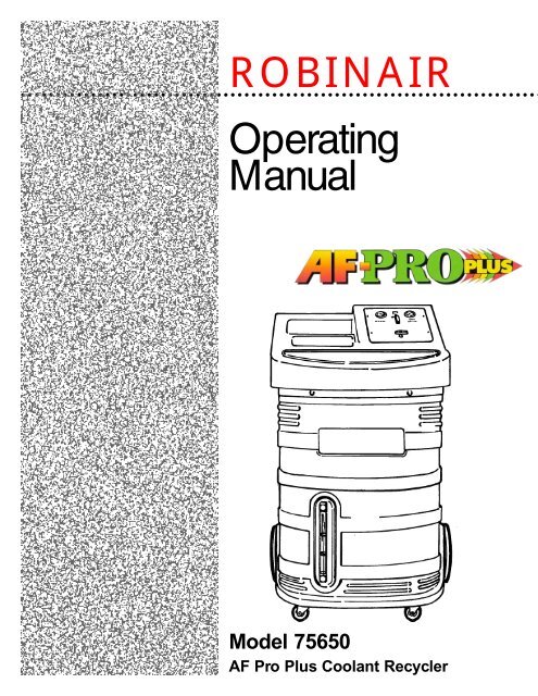
ROBINAIR<br />
○ ○ ○ ○ ○ ○ ○ ○ ○ ○ ○ ○ ○ ○ ○ ○ ○ ○ ○ ○ ○ ○ ○ ○ ○ ○ ○ ○ ○ ○ ○ ○ ○ ○ ○ ○ ○ ○ ○ ○ ○ ○ ○ ○ ○ ○ ○ ○ ○ ○ ○ ○ ○ ○ ○ ○ ○ ○ ○ ○ ○ ○ ○ ○ ○ ○ ○ ○ ○ ○ ○ ○ ○ ○<br />
Operating<br />
Manual<br />
Model <strong>75650</strong><br />
AF Pro Plus <strong>Coolant</strong> <strong>Recycler</strong>
Model <strong>75650</strong><br />
AF Pro Plus <strong>Coolant</strong> Recyc<br />
ycler<br />
READ ALL INSTRUCTIONS COMPLETELY!<br />
WARNING<br />
Make certain all safety devices are functioning properly before operating this equipment. Before operating, read and<br />
understand the instructions and warnings in this manual. During operation, follow the procedures described in this<br />
manual.<br />
Do not drink antifreeze or solution. If swallowed, give two glasses of water and induce vomiting. Call a physician.<br />
Ethylene glycol base. Avoid inhaling mist or hot vapors. If inhaled, remove to fresh air. Ethylene glycol<br />
causes birth defects in laboratory animals. Do not store in open or unlabeled containers. Wash thoroughly after<br />
handling. Solution may taste pleasant to animals, but is poisonous to them.<br />
Contact with antifreeze/coolant may cause injury. Wear proper protective equipment including safety goggles when<br />
operating this equipment. If contact with eyes occurs, flush with cold water for 30 minutes and call physician immediately.<br />
If contact with skin occurs, thoroughly wash area with soap and water.<br />
Do not use excessive RPM levels (high idle). The engine should run at low idle. Excessive RPM (high idle) may result in<br />
equipment malfunction and personal injuries.<br />
Hot antifreeze/coolant can burn skin and injure eyes. Wear proper protective equipment including safety goggles, and<br />
follow all procedures as set forth in this manual.<br />
Vehicle cooling systems which are hot are under pressure — opening a hot system except as described in this<br />
manual can cause an uncontrolled release of engine coolant. Do not open the radiator cap, and do not remove hoses<br />
from a hot system except as directed in this manual.<br />
Never run a vehicle engine without adequate ventilation. Breathing vehicle emissions can cause sickness, injury, or<br />
death.<br />
HANDLE BATTERY CONNECTION CABLES WITH EXTREME CAUTION — BATTERIES GENERATE EXPLOSIVE<br />
GASES DURING NORMAL BATTERY OPERATION. Working in the vicinity of a lead-acid or other automotive battery is<br />
dangerous. Wear complete eye protection. NEVER smoke or allow a spark or flame in the vicinity of a battery.<br />
Do not pressurize the vehicle cooling system above its pressure rating. Doing so may result in cooling system<br />
failure and the release of engine coolant.<br />
CAUTION! EQUIPMENT SHOULD BE OPERATED BY QUALIFIED PERSONNEL. Operator must be familiar with<br />
vehicle cooling systems, coolants, and the dangers they present.<br />
This equipment is not designed for any other purposes than testing cooling systems and exchanging used antifreeze/<br />
coolant with new or recycled product.<br />
Operator is responsible for complying with any and all applicable laws and regulations governing the use of this type of<br />
equipment as well as disposal of used antifreeze/coolant and used equipment and components.<br />
SAVE THESE INSTRUCTIONS!<br />
2 <strong>75650</strong> AF Pro Plus <strong>Coolant</strong> <strong>Recycler</strong>
Glossary of Terms ............................................................................................................. 3<br />
Introduction ...................................................................................................................... 4<br />
Operating Tips .............................................................................................................. 4<br />
Figure 1—Front View of Unit ...................................................................................... 4<br />
Figure 2—Rear View of Unit ....................................................................................... 4<br />
Set Up Instructions .......................................................................................................... 5<br />
Figure 3—Items Shipped With Unit ........................................................................... 5<br />
Figure 4—Rear View of Unit ....................................................................................... 6<br />
Figure 5—Front View of Unit ...................................................................................... 7<br />
Drain and Fill Procedures/Conventional Method ........................................................... 8<br />
Figure 6—Connections to Vehicle ................................................................................ 8<br />
Figure 7—Graduations on New <strong>Coolant</strong> Tank ........................................................... 9<br />
Figure 8—Control Panel ............................................................................................ 10<br />
Drain and Fill Procedures/Heater Hose Access Process .............................................. 13<br />
Figure 9—Tee Installation ........................................................................................... 13<br />
Figure 10—Hookup to Unit .......................................................................................... 14<br />
On-Vehicle Reinhibiting ................................................................................................. 15<br />
Figure 11—Connections to Vehicle ............................................................................ 15<br />
Refilling Using Vacuum Assist ...................................................................................... 19<br />
Checking For Leaks ........................................................................................................ 20<br />
Optional Power Fill.. ...................................................................................................... 21<br />
Emptying Procedure ....................................................................................................... 22<br />
Figure 10—Rear View of Unit ................................................................................... 22<br />
Flow Diagram ................................................................................................................. 23<br />
Replacement Parts List .................................................................................................. 23<br />
Maintenance Instructions .............................................................................................. 24<br />
Cleaning the Unit ....................................................................................................... 24<br />
Cleaning the Strainer ................................................................................................ 24<br />
Limited Warranty ........................................................................................................... 25<br />
Table Of<br />
Contents<br />
Antifreeze<br />
<strong>Coolant</strong><br />
Unit<br />
System<br />
Virgin product that has not been mixed with water<br />
A mixture of antifreeze and water<br />
The <strong>75650</strong> AF Pro Plus <strong>Coolant</strong> Exchanger<br />
The cooling system of the vehicle being serviced<br />
Glossary<br />
©1999 <strong>Robinair</strong>, SPX Corporation<br />
3
Introduction<br />
The <strong>75650</strong> AF Pro Plus <strong>Coolant</strong> <strong>Recycler</strong><br />
gives you everything you need to quickly<br />
remove, filter, and reinhibit coolant in a<br />
vehicle. Functions include drain and fill,<br />
pressure testing for leaks, and vacuum<br />
fill for use on an empty or partially<br />
empty system. The polyethylene portable<br />
cart provides durability and isn't damaged<br />
by coolant or other chemicals. The<br />
unit also has a tank within a tank<br />
feature, which keeps all serviced coolant<br />
at hand and doesn't require the use of<br />
additional storage vessels.<br />
The <strong>75650</strong> saves time and labor. It<br />
reduces the time needed for a typical<br />
drain and fill procedure by at least 50%.<br />
It also eliminates the need to wait for a<br />
hot system to cool down. This process<br />
also substantially reduces damaging air<br />
bubbles and air locks in a system.<br />
The unit provides a means for fast, easy<br />
filtering of a cooling system clogged by<br />
accumulations of rust and other contaminants.<br />
In addition, the pressure function can<br />
check the system for leaks after servicing<br />
the system.<br />
OPERATING TIPS<br />
1. Before filling a vehicle with new/<br />
recycled coolant, be sure there is an<br />
adequate amount of coolant in the unit’s<br />
New <strong>Coolant</strong> tank. The amount of coolant<br />
in the tank can be seen by looking at<br />
the sight glass on the front of the unit.<br />
An alarm will sound during operation if<br />
the New <strong>Coolant</strong> tank is empty.<br />
2. A 12-volt diaphragm pump circulates<br />
coolant during the drain and fill procedure.<br />
A 12V DC electric source is required.<br />
It is intended that the power<br />
leads be connected to the vehicle being<br />
serviced; proper operation will not drain<br />
the vehicle battery. To power the<br />
vacuum, you need a source of compressed<br />
air regulated at 75 psi (517 kPa, 5.2 bar)<br />
to 120 psi (827 kPa, 8.3 bar) with a 5 cfm<br />
(116 l/min.) capacity.<br />
Figure 1 — Front View of Unit<br />
Figure 2 — Rear View of Unit<br />
4 <strong>75650</strong> AF Pro Plus <strong>Coolant</strong> <strong>Recycler</strong>
The AF Pro Plus <strong>Coolant</strong> <strong>Recycler</strong> comes<br />
complete and ready to use.<br />
1. Unpack all materials listed below<br />
(and shown in Figure 3). Check to see<br />
that you have the following items:<br />
Set Up<br />
Instructions<br />
A (1) Large Radiator Cap Adapter<br />
B (1) Small Radiator Cap Adapter<br />
C (1) 5 /16” Siphon Hose Assembly<br />
D (1) 3 /8” Siphon Hose Assembly<br />
E (1) 1 1 /4” Hose Adapter<br />
F (1) 1 3 /8” Hose Adapter<br />
G (1) 1 1 /2” Hose Adapter<br />
H (2) Quick Connect Nipples (male<br />
thread)<br />
I (1) Quick Connect Nipple (female<br />
thread)<br />
J (2) Quick Connect Couplers<br />
K (2) Step Adapters<br />
L (1) <strong>Coolant</strong> Hose Assembly (Inlet)*<br />
M (1) <strong>Coolant</strong> Hose with View Window<br />
Assembly (Outlet)*<br />
N (2) Garden Hose Gaskets*<br />
ii *Not Shown<br />
i<br />
Part numbers are also listed in the Replacement Parts List on page 23.<br />
D<br />
C<br />
G I<br />
B<br />
E<br />
H<br />
A<br />
F<br />
J<br />
K<br />
Figure 3 — Items Shipped With Unit<br />
©1999 <strong>Robinair</strong>, SPX Corporation<br />
5
Set Up<br />
Instructions<br />
2. Connect a 1 /4” male fitting to the air<br />
supply inlet located on the upper left<br />
side of the unit’s rear panel<br />
(see Figure 5). You will have to<br />
furnish this fitting.<br />
3. Add at least three gallons (11.4 liters)<br />
of coolant by pouring the coolant into<br />
the large sink located on the top front<br />
of the unit. Use a 50/50 mix of new<br />
antifreeze and water or recycled<br />
coolant which has been adjusted to a<br />
50/50 mix.<br />
Strainer<br />
Air Inlet<br />
Hose<br />
Storage<br />
Power Cable<br />
Reinhibitor<br />
Injector<br />
<strong>Coolant</strong> Outlet<br />
Port<br />
<strong>Coolant</strong> Inlet<br />
Port<br />
5 Micron<br />
Filter<br />
20 Micron<br />
Filter<br />
<strong>Coolant</strong><br />
Level<br />
Used <strong>Coolant</strong><br />
Tank<br />
Drain Port<br />
Figure 4 — Rear View of Unit<br />
4. Connect the solid black hose to the<br />
<strong>Coolant</strong> Inlet port. Connect the hose<br />
with the clear window to the <strong>Coolant</strong><br />
Outlet port.<br />
5. Attach a quick connect coupler to the<br />
end of each hose. Insert a rubber hose<br />
gasket into each step adapter.<br />
6 <strong>75650</strong> AF Pro Plus <strong>Coolant</strong> <strong>Recycler</strong>
6. Make sure that the filter housings<br />
are tightened securely. Keep extra<br />
filters on hand because they must be<br />
replaced.<br />
7. Change the filters whenever the<br />
pressure drops below normal operating<br />
psi. Either filter could become<br />
clogged quickly, however, you can<br />
expect the 20 micron filter to become<br />
clogged first.<br />
8. Observe the clarity of the coolant<br />
through the <strong>Coolant</strong> Outlet hose view<br />
window. If the coolant does not run<br />
clear after the entire filtration<br />
process, the filters need to be replaced.<br />
9. To change filters, turn the main<br />
power switch to OFF. Unscrew the<br />
filter housing(s), remove the dirty<br />
filter(s), and replace with a new<br />
filter(s). Reinstall the filter<br />
housing(s) and tighten securely.<br />
Set Up<br />
Instructions<br />
Storage Area<br />
Control Panel<br />
Sink<br />
(New <strong>Coolant</strong><br />
Tank)<br />
Sight<br />
Glass<br />
Figure 5 — Front View of Unit<br />
©1999 <strong>Robinair</strong>, SPX Corporation<br />
7
Drain & Fill<br />
Procedures/<br />
Conventional<br />
Method<br />
WARNING!<br />
Contact with antifreeze/coolant can<br />
cause injury. Wear proper protective<br />
equipment and read the warnings at the<br />
beginning of this manual. Follow<br />
instructions carefully. Failure to perform<br />
the procedures as described can result<br />
in personal injury and damage to the<br />
vehicle and equipment.<br />
The AF Pro Plus <strong>Coolant</strong> <strong>Recycler</strong> allows<br />
you to quickly filter and inhibit the<br />
coolant in the vehicle. This process<br />
substantially reduces air bubbles and<br />
prevents air locks in the system. The<br />
entire process should take 15 to 20<br />
minutes.<br />
IMPORTANT! To protect the pump and<br />
prevent air from entering the system, an<br />
alarm will sound if there is not enough<br />
coolant in the unit.<br />
CAUTION! Before performing a drain<br />
and fill procedure, be sure to purge the<br />
vehicle’s cooling system of any flush<br />
product. Follow the flush manufacturer’s<br />
directions.<br />
This procedure can be performed on an<br />
engine that is cool or hot. The process<br />
can be completed faster if the engine is at<br />
operating temperature.<br />
<strong>Coolant</strong> Inlet<br />
Hose<br />
<strong>Coolant</strong> Outlet<br />
Hose<br />
Heater Core<br />
Radiator<br />
Engine<br />
Block<br />
Water<br />
Pump<br />
Figure 6 — Connections to Vehicle<br />
8 <strong>75650</strong> AF Pro Plus <strong>Coolant</strong> <strong>Recycler</strong>
1. Position the AF Pro Plus near the<br />
vehicle’s engine compartment.<br />
CAUTION! Be sure the Used <strong>Coolant</strong><br />
tank has enough room to hold the<br />
vehicle’s capacity.<br />
2. In order to fill the New <strong>Coolant</strong> tank<br />
with the proper amount of new or<br />
recycled coolant, check the sight<br />
glass on the front of the unit for the<br />
graduation levels. These levels depict<br />
the amount of coolant in the tank.<br />
Remember to check the manufacturer’s<br />
specifications for engine<br />
coolant capacity. Use a 50/50 mix of<br />
new antifreeze and water or recycled<br />
coolant which has been adjusted to a<br />
50/50 mix.<br />
Once you have filled the New <strong>Coolant</strong><br />
tank, set the top ring on the sight<br />
glass in line with the level of coolant<br />
in the tank. Place the second ring at<br />
the level of coolant needed to meet<br />
the vehicle's requirements. This<br />
serves as a guide when measuring<br />
coolant in the tank.<br />
WARNING!<br />
Handle battery connection cables with<br />
extreme caution — batteries generate<br />
explosive gases during normal battery<br />
operation. Working in the vicinity of a<br />
lead-acid or other automotive battery is<br />
dangerous. Wear complete eye protection.<br />
NEVER smoke or allow a spark or<br />
flame in the vicinity of a battery.<br />
3. Connect the red power lead to the “+”<br />
(positive) post of the vehicle battery<br />
or to another 12V power source. Then<br />
connect the black power lead to an<br />
engine ground, not the battery “-”<br />
terminal.<br />
Verify that the Power Switch is in the<br />
OFF position.<br />
4. If the system is hot and pressurized,<br />
relieve the pressure in the system as<br />
follows:<br />
• Remove the vehicle’s overflow tank<br />
hose from the fitting on the radiator<br />
neck.<br />
Drain & Fill<br />
Procedures/<br />
Conventional<br />
Method<br />
Figure 7 —<br />
Graduations on<br />
New <strong>Coolant</strong> Tank<br />
©1999 <strong>Robinair</strong>, SPX Corporation<br />
9
Drain & Fill<br />
Procedures/<br />
Conventional<br />
Method<br />
• Attach the correct size vacuum<br />
siphon hose to the overflow fitting on<br />
the vehicle, then connect the Quick<br />
Coupler of the <strong>Coolant</strong> Inlet hose<br />
(solid black) to the siphon hose.<br />
• Turn the upper control panel valve to<br />
DRAIN AND FILL. Turn the lower<br />
control panel valve to NEW<br />
COOLANT.<br />
• Connect the air supply hose to the air<br />
supply inlet fitting on the back left of<br />
the unit. Make sure incoming pressure<br />
is regulated between 75 psi (517<br />
kPa, 5.2 bar) and 120 psi (827 kPa,<br />
8.3 bar) at 5 cfm (116 l/m).<br />
• When the vacuum gauge on the<br />
control panel shows 20 in. Hg of<br />
vacuum, slowly remove the vehicle’s<br />
radiator cap.<br />
• Disconnect the siphon hose from the<br />
vehicle's radiator neck.<br />
If the system is cold:<br />
• Slowly remove the vehicle’s radiator<br />
cap.<br />
• Turn the upper control panel valve to<br />
DRAIN AND FILL. Turn the lower<br />
control panel valve to NEW<br />
COOLANT.<br />
• Connect the air supply hose to the air<br />
supply inlet fitting on the back left of<br />
the unit. Make sure incoming pressure<br />
is regulated between 75 psi (517<br />
kPa, 5.2 bar) and 120 psi (827 kPa,<br />
8.3 bar) at 5 cfm (116 l/m).<br />
5. Remove the cap on the vehicle’s<br />
overflow tank. Then attach a vacuum<br />
siphon hose to the <strong>Coolant</strong> Inlet hose<br />
(solid black). To remove any remaining<br />
coolant, place the vacuum siphon<br />
hose in the over-flow tank.<br />
6. Place the vacuum siphon hose<br />
attached to the <strong>Coolant</strong> Inlet hose<br />
(solid black) in the radiator. Remove<br />
enough coolant to lower the coolant<br />
level in the radiator below the level of<br />
the upper radiator inlet hose fitting.<br />
7. Disconnect the air supply.<br />
8. Replace the caps on the vehicle’s<br />
radiator and overflow tank and<br />
reconnect the overflow hose.<br />
PRESSURE<br />
TRANSFER<br />
DRAIN<br />
AND FILL<br />
VACUUM<br />
VACUUM<br />
FILL<br />
COOLANT SOURCE<br />
NEW<br />
USED<br />
Figure 8 — Control Panel<br />
10<br />
<strong>75650</strong> AF Pro Plus <strong>Coolant</strong> <strong>Recycler</strong>
9. Disconnect the vacuum siphon hose<br />
from the <strong>Coolant</strong> Inlet hose (solid<br />
black). Store the siphon hose and its<br />
fitting on the side brackets.<br />
10. Examine the vehicle’s upper radiator<br />
hose to determine which location (at<br />
either the radiator or engine) will be<br />
most convenient to remove one end<br />
of the radiator hose and to install the<br />
hose adapter.<br />
11. Remove the hose clamp securing the<br />
radiator hose to the radiator or the<br />
engine, and remove the hose from the<br />
radiator or engine. Be careful not to<br />
overstress the radiator hose fitting.<br />
12. Connect the male quick connect<br />
nipples to both step adapters.<br />
13. Insert a step adapter onto the engine<br />
side hose and another onto the<br />
radiator side hose.<br />
14. Secure the step adapters to the<br />
radiator hose and adapter hose with<br />
hose clamps. You will have to<br />
supply these clamps.<br />
15. Connect the <strong>Coolant</strong> Outlet hose<br />
(with clear window) to the radiator<br />
side connection and open the valve<br />
on <strong>Coolant</strong> Outlet hose.<br />
16. Connect the <strong>Coolant</strong> Inlet hose (solid<br />
black) to the engine side connection.<br />
17. Turn the upper control panel valve to<br />
DRAIN AND FILL and turn the<br />
lower control panel valve to NEW<br />
COOLANT. Turn the main power<br />
switch ON.<br />
WARNING!<br />
Before starting the vehicle, be sure it is<br />
in Park or Neutral with the emergency<br />
brake on.<br />
Do not use excessive RPM levels (high<br />
idle). The engine should run at low idle.<br />
Excessive RPM (high idle) may result in<br />
equipment malfunction and personnel<br />
injuries.<br />
Never run a vehicle without adequate<br />
ventilation. Breathing vehicle emissions<br />
can cause sickness, injury or death.<br />
Keep hands and service components/tools<br />
away from moving parts on the vehicle.<br />
18. Start the vehicle. <strong>Coolant</strong> will be<br />
pumped from the New <strong>Coolant</strong> tank<br />
into the vehicle. Used coolant will be<br />
transferred to the Used <strong>Coolant</strong> tank.<br />
Note: <strong>Coolant</strong> exchange will not occur<br />
unless the thermostat is open. If the<br />
thermostat will not open, turn the vehicle<br />
off, and check the cooling system components.<br />
If the flow stops, monitor the<br />
engine temperature. Continue to run the<br />
vehicle — the thermostat should open<br />
and the flow will start.<br />
IMPORTANT! If the alarm sounds during<br />
the drain and fill process, immediately<br />
turn off the vehicle’s engine to avoid<br />
discharging excess coolant from the<br />
cooling system. Set the control panel<br />
switch to OFF.<br />
Drain & Fill<br />
Procedures/<br />
Conventional<br />
Method<br />
©1999 <strong>Robinair</strong>, SPX Corporation<br />
11
Drain & Fill<br />
Procedures/<br />
Conventional<br />
Method<br />
19. When the correct amount of coolant<br />
has been exchanged in the vehicle,<br />
close the valve on the <strong>Coolant</strong> Outlet<br />
hose (with clear window). Wait 10 to<br />
15 seconds, then turn off the engine<br />
and set the control panel switch to<br />
OFF.<br />
WARNING!<br />
The radiator may contain hot coolant.<br />
Wear eye and hand protection.<br />
20. Disconnect the <strong>Coolant</strong> Outlet hose<br />
(with clear window) from the step<br />
adapter. Then, disconnect the<br />
<strong>Coolant</strong> Inlet hose from the other<br />
step adapter.<br />
21. Remove the hose connectors and<br />
clamps from the radiator hose and<br />
the rubber adapter hose. Disconnect<br />
from the radiator side first, then<br />
disconnect from the engine side.<br />
22. Reconnect the radiator hose to the<br />
fitting (radiator or engine) on the<br />
vehicle from which it was removed.<br />
Secure with a clamp.<br />
23. Remove the vehicle’s radiator cap.<br />
With the siphon hose attached to the<br />
<strong>Coolant</strong> Outlet hose (with clear<br />
window), turn the control panel<br />
switch to ON, fill the vehicle’s overflow<br />
tank and top off the radiator to<br />
the correct level. Use the valve on the<br />
<strong>Coolant</strong> Outlet hose (with clear<br />
window) to control the flow.<br />
24. Close the valve on the <strong>Coolant</strong> Outlet<br />
hose (with clear window), then<br />
disconnect the siphon hose from the<br />
<strong>Coolant</strong> Outlet hose.<br />
25. Set the control panel switch to OFF.<br />
Replace the radiator and overflow<br />
caps.<br />
26. Disconnect the black power lead,<br />
then disconnect the red power lead<br />
from the vehicle battery or 12V<br />
power source. Store the hoses and<br />
power leads on the side brackets. If<br />
the Used <strong>Coolant</strong> tank is full, you<br />
may drain it by following the steps on<br />
page 18 of this manual.<br />
The drain and fill procedure is now<br />
complete. Start the vehicle and check<br />
for leaks (see Checking for Leaks on<br />
page 16).<br />
12<br />
<strong>75650</strong> AF Pro Plus <strong>Coolant</strong> <strong>Recycler</strong>
Installing The Tee<br />
Use this process to reverse the flow of<br />
coolant in order to loosen and remove<br />
scale, rust, and other contaminants from<br />
the cooling system.<br />
1. On the vehicle, locate the heater<br />
outlet hose that runs between the<br />
heater core (in the fire wall) and the<br />
water pump or radiator. The tee will<br />
be installed in the heater outlet hose<br />
(see Figure 9).<br />
CAUTION! Be sure that you locate<br />
the heater outlet hose and not the<br />
heater inlet hose that runs between<br />
the heater core and the engine block<br />
or thermostat housing.<br />
2. Find a convenient spot on the heater<br />
outlet hose to install the tee. Clamp<br />
pinch-off pliers on the hose two or<br />
four inches on each side of the<br />
installation point.<br />
3. Using a hose cutter, cut completely<br />
through the heater outlet hose at the<br />
selected point.<br />
4. Slide a hose clamp (not supplied) onto<br />
each cut section of the heater hose to<br />
pinch-off pliers. Select the correct<br />
size tee (not supplied) to fit on the<br />
hose sections. Connect the tee to the<br />
hose sections. Slide each clamp onto<br />
the connection and tighten the hose<br />
clamps.<br />
NOTE: If the tee is not already capped,<br />
install a tee cap on the tee. Make sure<br />
the cap contains a rubber washer.<br />
5. Remove the pinch-off pliers.<br />
NOTE: This tee will permanently<br />
remain in place on the vehicle.<br />
Drain & Fill<br />
Procedures/<br />
Heater Hose<br />
Access<br />
Process<br />
Heater Core<br />
Heater Inlet<br />
Hose<br />
Upper Hose<br />
Water Pump<br />
Engine<br />
Block<br />
Radiator<br />
Heater Outlet<br />
Hose<br />
Pinch-Off<br />
Pliers<br />
Tee with clamps<br />
on both sides<br />
Figure 9 - Tee Installation<br />
©1999 <strong>Robinair</strong>, SPX Corporation<br />
13
Drain & Fill<br />
Procedures/<br />
Heater Hose<br />
Access<br />
Process<br />
1. Follow steps 1 - 14 from the Drain &<br />
Fill Procedures/Conventional<br />
Method section (pages 8-11).<br />
2. Using pinch-off pliers, pinch off the<br />
heater hose on both sides of the tee.<br />
Remove the tee cap and connect the<br />
quick connect nipple (female) to the<br />
tee. Remove the pinch-off pliers<br />
between the tee and the heater core<br />
(see Figure 10).<br />
3. Connect the <strong>Coolant</strong> Outlet hose<br />
(with view window) to the quick<br />
connect nipple and open the valve on<br />
the <strong>Coolant</strong> Outlet hose. Connect the<br />
<strong>Coolant</strong> Inlet hose (solid black) to the<br />
radiator side connector.<br />
*<strong>Coolant</strong> will be pumped from the<br />
New <strong>Coolant</strong> tank into the vehicle.<br />
Used coolant will be transferred to<br />
the Used <strong>Coolant</strong> tank.<br />
WARNING! DO NOT START THE<br />
VEHICLE! This procedure does not<br />
require the vehicle to run during Drain<br />
& Fill or recycling procedure. Failure<br />
to perform procedures as described<br />
can result in personal injury and<br />
damage to the vehicle and equipment.<br />
4. When the correct amount of coolant<br />
has been exchanged in the vehicle,<br />
close the valve on the <strong>Coolant</strong> Outlet<br />
hose (with view window) and set the<br />
control panel switch to OFF.<br />
5. Disconnect the <strong>Coolant</strong> Outlet hose<br />
(with view window) from the quick<br />
connect nipple. Disconnect the<br />
<strong>Coolant</strong> Inlet hose (solid black) from<br />
the step adapter.<br />
6. Remove the hose connectors and<br />
clamps from the radiator hose and<br />
the rubber adapter hose. Disconnect<br />
from the radiator side first, then<br />
disconnect from the engine side.<br />
7. Reconnect the radiator hose to the<br />
fitting (radiator or engine) on the<br />
vehicle from which it was removed.<br />
Secure with a clamp.<br />
8. Remove the vehicle’s radiator cap.<br />
With the siphon hose attached to the<br />
<strong>Coolant</strong> Outlet hose (w/clear window),<br />
turn the control panel switch to<br />
ON, fill the vehicle’s overflow tank<br />
and top off the radiator to the correct<br />
level. Use the valve on the <strong>Coolant</strong><br />
Outlet hose (w/clear window) to<br />
control the flow.<br />
9. Close the valve on the <strong>Coolant</strong> Outlet<br />
hose (w/clear window), then disconnect<br />
the siphon hose from the <strong>Coolant</strong><br />
Outlet hose.<br />
10. Set the control panel switch to OFF.<br />
Replace the radiator and overflow<br />
caps.<br />
11. After disconnecting the quick connect<br />
nipple, install a cap with a rubber<br />
washer onto the tee.<br />
12. Disconnect the black power lead,<br />
then disconnect the red power lead<br />
from the vehicle battery or 12V<br />
power source. Store the hoses and<br />
power leads on the side brackets. If<br />
the Used <strong>Coolant</strong> tank is full, you<br />
may drain it (see page 18).<br />
Heater<br />
Core<br />
<strong>Coolant</strong> Inlet<br />
Hose<br />
Radiator<br />
<strong>Coolant</strong><br />
Outlet<br />
Hose<br />
Figure 10 -<br />
Hookup to Unit<br />
14<br />
<strong>75650</strong> AF Pro Plus <strong>Coolant</strong> <strong>Recycler</strong>
WARNING!<br />
Contact with antifreeze/coolant can<br />
cause injury. Wear proper protective<br />
equipment and read the warnings at the<br />
beginning of this manual.<br />
Follow instructions carefully. Failure to<br />
perform the procedures as described<br />
can result in personal injury and damage<br />
to the vehicle and equipment.<br />
CAUTION! During filtering, unit components<br />
are extremely hot! Wear adequate<br />
eye and hand protection.<br />
The AF Pro Plus <strong>Coolant</strong> <strong>Recycler</strong> allows<br />
you to quickly filter and reinhibit the<br />
coolant in the vehicle. The entire process<br />
should take 15 to 20 minutes.<br />
This procedure can be performed on an<br />
engine that is cool or hot. The process<br />
can be completed faster if the engine is at<br />
operating temperature.<br />
1. Position the AF Pro Plus near the<br />
vehicle’s engine compartment.<br />
CAUTION! Be sure the Used <strong>Coolant</strong><br />
tank has enough room to hold the<br />
vehicle’s capacity.<br />
WARNING!<br />
Handle battery connection cables with<br />
extreme caution — batteries generate<br />
explosive gases during normal battery<br />
operation. Working in the vicinity of a<br />
lead-acid or other automotive battery is<br />
dangerous. Wear complete eye protection.<br />
NEVER smoke or allow a spark or<br />
flame in the vicinity of a battery.<br />
2. Connect the red power lead to the “+”<br />
(positive) post of the vehicle battery<br />
or to another 12V power source. Then<br />
connect the black power lead to an<br />
engine ground, not the battery “-”<br />
terminal.<br />
Verify that the Power Switch is in the<br />
OFF position.<br />
3. If the system is hot and pressurized,<br />
relieve the pressure in the system as<br />
follows:<br />
• Remove the vehicle’s overflow tank<br />
hose from the fitting on the radiator<br />
neck.<br />
On-Vehicle<br />
Reinhibiting<br />
CAUTION! Be sure<br />
used coolant<br />
appears on the<br />
<strong>Coolant</strong> Level on<br />
the Used <strong>Coolant</strong><br />
tank. There MUST<br />
be coolant present<br />
before starting<br />
this process. See<br />
page 6 for the<br />
location of the<br />
<strong>Coolant</strong> Level.<br />
<strong>Coolant</strong> Inlet<br />
Hose<br />
<strong>Coolant</strong> Outlet<br />
Hose<br />
Heater Core<br />
Radiator<br />
Engine<br />
Block<br />
Water<br />
Pump<br />
Figure 11 — Connections to Vehicle<br />
©1999 <strong>Robinair</strong>, SPX Corporation<br />
15
On-Vehicle<br />
Reinhibiting<br />
• Attach the correct size vacuum<br />
siphon hose to the overflow fitting on<br />
the vehicle, then connect the Quick<br />
Coupler of the <strong>Coolant</strong> Inlet hose<br />
(solid black) to the siphon hose.<br />
• Turn the upper control panel valve to<br />
DRAIN AND FILL. Turn the lower<br />
control panel valve to NEW<br />
COOLANT.<br />
• Connect the air supply hose to the air<br />
supply inlet fitting on the back left of<br />
the unit. Make sure incoming pressure<br />
is regulated between 75 psi (517<br />
kPa, 5.2 bar) and 120 psi (827 kPa,<br />
8.3 bar) at 5 cfm (116 l/m).<br />
• When the vacuum gauge on the<br />
control panel shows 20 in. Hg of<br />
vacuum, slowly remove the vehicle’s<br />
radiator cap.<br />
• Disconnect the siphon hose from the<br />
vehicle's radiator neck.<br />
If the system is cold:<br />
• Slowly remove the vehicle’s radiator<br />
cap.<br />
• Turn the upper control panel valve to<br />
DRAIN AND FILL. Turn the lower<br />
control panel valve to NEW<br />
COOLANT.<br />
• Connect the air supply hose to the air<br />
supply inlet fitting on the back left of<br />
the unit. Make sure incoming pressure<br />
is regulated between 75 psi (517<br />
kPa, 5.2 bar) and 120 psi (827 kPa,<br />
8.3 bar) at 5 cfm (116 l/m).<br />
4. Remove the cap on the vehicle's<br />
overflow tank. Check the freeze point<br />
of the coolant using the test strips<br />
provided (follow directions on the<br />
strip) or with any other acceptable<br />
method. The correct freeze point<br />
level at a 50/50 mix is -34F (-36.7C).<br />
5. Attach a vacuum siphon hose to the<br />
<strong>Coolant</strong> Inlet hose (solid black). To<br />
remove any remaining coolant, place<br />
the vacuum siphon hose in the overflow<br />
tank.<br />
6. Place the vacuum siphon hose<br />
attached to the <strong>Coolant</strong> Inlet hose<br />
(solid black) in the radiator. Remove<br />
enough coolant to lower the coolant<br />
level in the radiator below the level of<br />
the upper radiator inlet hose fitting.<br />
7. Disconnect the air supply.<br />
8. Replace the caps on the vehicle’s<br />
radiator and overflow tank. Reconnect<br />
the overflow hose.<br />
PRESSURE<br />
DRAIN<br />
VACUUM<br />
AND FILL<br />
TRANSFER VACUUM<br />
FILL<br />
COOLANT SOURCE<br />
NEW<br />
USED<br />
Figure 11 — Control Panel<br />
16<br />
<strong>75650</strong> AF Pro Plus <strong>Coolant</strong> <strong>Recycler</strong>
9. Disconnect the vacuum siphon hose<br />
from the <strong>Coolant</strong> Inlet hose (solid<br />
black). Store the siphon hose and its<br />
fitting in the storage area.<br />
10. Examine the vehicle’s upper radiator<br />
hose to determine which location (at<br />
either the radiator or engine) will be<br />
most convenient to remove one end<br />
of the radiator hose and to install the<br />
hose adapter.<br />
11. Remove the hose clamp securing the<br />
radiator hose to the radiator or the<br />
engine, and remove the hose from the<br />
radiator or engine. Be careful not to<br />
overstress the radiator hose fitting.<br />
12. Connect the male quick connect<br />
nipples to both step adapters.<br />
13. Insert a step adapter onto the engine<br />
side hose and another onto the<br />
radiator side hose.<br />
14. Secure the step adapters to the<br />
radiator hose and adapter hose with<br />
hose clamps. You will have to<br />
supply these clamps.<br />
15. Connect the <strong>Coolant</strong> Outlet hose<br />
(with clear window) to the radiator<br />
side connection and open the valve<br />
on <strong>Coolant</strong> Outlet hose.<br />
16. Connect the <strong>Coolant</strong> Inlet hose (solid<br />
black) to the engine side connection.<br />
17. Unscrew the Reinhibitor Injector<br />
bottle on the back of the unit. Add<br />
reinhibitor (not included, see the<br />
Replacement Parts List) to the bottle<br />
based on the vehicle's coolant capacity:<br />
• 6-15 quarts (6-14 liters) - add one<br />
bottle, 12 fl. oz. (355ml)<br />
• 16-30 quarts (15-28 liters) - add two<br />
bottles, 24 fl. oz. (710ml)<br />
You may have to repeat this process<br />
several times during this procedure<br />
to meet the vehicle's capacity.<br />
18. Turn the control panel valve to<br />
DRAIN AND FILL. Turn the lower<br />
control panel valve to USED COOL-<br />
ANT.<br />
19. Turn the main power ON.<br />
WARNING!<br />
Before starting the vehicle, be sure it is<br />
in Park or Neutral with the emergency<br />
brake on.<br />
Do not use excessive RPM levels (high<br />
idle). The engine should run at low idle.<br />
Excessive RPM (high idle) may result in<br />
equipment malfunction and personnel<br />
injuries.<br />
Never run a vehicle without adequate<br />
ventilation. Breathing vehicle emissions<br />
can cause sickness, injury or death.<br />
Keep hands and service components/<br />
tools away from moving parts on the<br />
vehicle.<br />
20. Start the vehicle. <strong>Coolant</strong> from the<br />
engine will be circulated into the<br />
Used <strong>Coolant</strong> tank, then pumped<br />
through the unit's filters and the<br />
coolant will be returned to the<br />
engine.<br />
Note: <strong>Coolant</strong> exchange will not occur<br />
unless the thermostat is open. If the<br />
thermostat will not open, turn the<br />
vehicle off, and check the cooling<br />
system components. If the flow stops,<br />
monitor the engine temperature.<br />
Continue to run the vehicle — the<br />
thermostat should open and the flow<br />
will start.<br />
IMPORTANT! <strong>Coolant</strong> exchange will not<br />
occur unless the thermostat is open. If<br />
the thermostat will not open, stop the<br />
engine and check the cooling system<br />
components. If the flow stops, monitor<br />
the engine temperature. Continue to run<br />
the engine - the thermostat should and<br />
the flow will start.<br />
21. Open the valve on the Reinhibitor<br />
Injector. Allow reinhibitor to be<br />
drawn into the unit. When the bottle<br />
is almost empty, turn the valve off.<br />
Unscrew the bottle and refill it with<br />
additional reinhibitor (if required).<br />
Screw the bottle back onto the unit<br />
and repeat this process as required.<br />
On-Vehicle<br />
Reinhibiting<br />
CAUTION! Do not<br />
allow air to be<br />
drawn into the<br />
unit. Damage to<br />
equipment and/or<br />
vehicle may occur.<br />
©1999 <strong>Robinair</strong>, SPX Corporation<br />
17
On-Vehicle<br />
Reinhibiting<br />
22. Allow the coolant to circulate between<br />
the vehicle and the unit at<br />
least two cycles. Wait 10 to 15 seconds,<br />
then turn off the engine and set<br />
the control panel switch to OFF.<br />
WARNING!<br />
The radiator may contain hot coolant.<br />
Wear eye and hand protection.<br />
23. Disconnect the <strong>Coolant</strong> Outlet hose<br />
(with clear window) from the step<br />
adapter. Then, disconnect the<br />
<strong>Coolant</strong> Inlet hose from the other<br />
step adapter.<br />
24. Remove the hose connectors and<br />
clamps from the radiator hose and<br />
the rubber adapter hose. Disconnect<br />
from the radiator side first, then<br />
disconnect from the engine side.<br />
25. Reconnect the radiator hose to the<br />
fitting (radiator or engine) on the<br />
vehicle from which it was removed.<br />
Secure with a clamp.<br />
26. Remove the vehicle’s radiator cap.<br />
With the siphon hose attached to the<br />
<strong>Coolant</strong> Outlet hose (with clear<br />
window), turn the control panel<br />
switch to ON, fill the vehicle’s overflow<br />
tank and top off the radiator to<br />
the correct level. Use the valve on the<br />
<strong>Coolant</strong> Outlet hose (with clear<br />
window) to control the flow.<br />
27. Close the valve on the <strong>Coolant</strong> Outlet<br />
hose (with clear window), then<br />
disconnect the siphon hose from the<br />
<strong>Coolant</strong> Outlet hose.<br />
28. Set the control panel switch to OFF.<br />
Replace the radiator and overflow<br />
caps.<br />
29. Disconnect the black power lead,<br />
then disconnect the red power lead<br />
from the vehicle battery or 12V<br />
power source. Store the hoses and<br />
power leads on the side brackets. If<br />
the Used <strong>Coolant</strong> tank is full, you<br />
may drain it by following the steps on<br />
page 18 of this manual.<br />
The On-Vehicle Reinhibiting procedure is<br />
now complete. Start the vehicle and<br />
check for leaks (see Checking for Leaks<br />
on page 16).<br />
18<br />
<strong>75650</strong> AF Pro Plus <strong>Coolant</strong> <strong>Recycler</strong>
CAUTION! Do not perform this procedure<br />
on a full system!<br />
If you have to make repairs to the vehicle,<br />
the vacuum function lets you fill a<br />
partially or completely empty system<br />
instead of draining and filling at the<br />
same time.<br />
Be sure the New <strong>Coolant</strong> tank has the<br />
amount of antifreeze/coolant needed for<br />
the vehicle being serviced by checking<br />
the sight glass on the front of the unit.<br />
Also, check the manufacturer’s specifications<br />
for engine coolant capacity. Use a<br />
50/50 mix of new antifreeze and water or<br />
recycled coolant which has been adjusted<br />
to a 50/50 mix.<br />
WARNING!<br />
The radiator may contain hot coolant.<br />
Wear eye and hand protection.<br />
1. First, connect the red power lead to<br />
the “+” (positive) post of the vehicle<br />
battery or to another 12V power<br />
source. Then connect the black power<br />
lead to an engine ground, not the<br />
battery “-” terminal.<br />
WARNING!<br />
Handle battery connection cables with<br />
extreme caution — batteries generate<br />
explosive gases during normal battery<br />
operation. Working in the vicinity of a<br />
lead-acid or other automotive battery is<br />
dangerous. Wear complete eye protection.<br />
NEVER smoke or allow a spark or<br />
flame in the vicinity of a battery.<br />
2. Slowly remove the vehicle’s radiator<br />
cap (on vehicles with closed loop<br />
cooling systems, remove the overflow<br />
tank cap).<br />
3. Connect and tighten the appropriate<br />
size radiator cap adapter to the<br />
radiator fill neck. Connect the <strong>Coolant</strong><br />
Inlet hose (solid black) to the<br />
radiator service cap adapter.<br />
4. Turn the upper control panel valve to<br />
DRAIN AND FILL and the lower<br />
control panel valve to NEW COOL-<br />
ANT.<br />
5. Connect the air supply hose to the air<br />
supply inlet fitting. Be sure incoming<br />
pressure is regulated between 75 psi<br />
(517 kPa, 5.2 bar) and 120 psi (827<br />
kPa, 8.3 bar) at 5 cfm (116 l/m).<br />
Allow the system to pull down to 20-<br />
28 in. Hg.<br />
6. Disconnect the air supply. Turn the<br />
control panel valve to VAC FILL.<br />
When the vacuum gauge reaches<br />
zero, disconnect the <strong>Coolant</strong> Inlet<br />
hose (solid black) from the radiator<br />
cap adapter.<br />
7. Remove the radiator cap adapter and<br />
the cap from the overflow tank.<br />
8. Attach one of the unit’s siphon hose<br />
assemblies to the <strong>Coolant</strong> Outlet hose<br />
(w/clear window). Turn the control<br />
panel valve to DRAIN AND FILL.<br />
Turn the valve on the <strong>Coolant</strong> Outlet<br />
hose to OFF, then set the control<br />
panel switch to ON. Using the valve<br />
on the <strong>Coolant</strong> Outlet hose to control<br />
the flow, fill the radiator and overflow<br />
tank to the correct level.<br />
9. When the system has been filled, set<br />
the control panel switch to OFF and<br />
remove the siphon hose and store it.<br />
Replace the caps on the radiator and<br />
overflow tank.<br />
10. Disconnect the black power lead,<br />
then disconnect the red power lead<br />
from the vehicle battery or 12V<br />
power source. Store the hoses and<br />
power leads on the side brackets.<br />
11. If the Used <strong>Coolant</strong> tank is full, you<br />
can transfer the used coolant to a<br />
suitable storage container as described<br />
in the Optional Power Fill<br />
section on page 18.<br />
Refilling<br />
Using<br />
Vacuum<br />
Assist<br />
©1999 <strong>Robinair</strong>, SPX Corporation<br />
19
Checking<br />
For Leaks<br />
20<br />
You can check a cooling system for leaks<br />
using the built-in pressure testing<br />
function prior to servicing or after. If the<br />
system holds a pressure level, you know<br />
it is leak-free and you can refill it with<br />
coolant. However, if it doesn’t hold a<br />
pressure level, you know there is a leak<br />
that must be repaired.<br />
Be sure the New <strong>Coolant</strong> tank has the<br />
amount of antifreeze/coolant needed for<br />
the vehicle being serviced by checking<br />
the sight glass on the front of the unit.<br />
Also, check the manufacturer’s specifications<br />
for engine coolant capacity. Use a<br />
50/50 mix of new antifreeze and water or<br />
recycled coolant which has been adjusted<br />
to a 50/50/ mix.<br />
WARNING!<br />
Handle battery connection cables with<br />
extreme caution — batteries generate<br />
explosive gases during normal battery<br />
operation. Working in the vicinity of a<br />
lead-acid or other automotive battery is<br />
dangerous. Wear complete eye protection.<br />
NEVER smoke or allow a spark or<br />
flame in the vicinity of a battery.<br />
1. First, connect the red power lead to<br />
the “+” (positive) post of the vehicle<br />
battery or to another 12V power<br />
source. Then connect the black power<br />
lead to an engine ground, not the<br />
battery “-” terminal.<br />
WARNING!<br />
The radiator may contain hot coolant.<br />
Wear eye and hand protection.<br />
2. Slowly remove the vehicle’s radiator<br />
cap, connect and tighten the appropriate<br />
radiator cap adapter, then<br />
connect the <strong>Coolant</strong> Outlet hose<br />
(with clear window) to the radiator<br />
cap adapter.<br />
3. Turn the upper control panel valve to<br />
DRAIN AND FILL and the lower<br />
control panel valve to NEW COOL-<br />
ANT. Set the control panel switch to<br />
ON.<br />
<strong>75650</strong> AF Pro Plus <strong>Coolant</strong> <strong>Recycler</strong> 4. Open the valve on the <strong>Coolant</strong> Outlet<br />
hose (with clear window). The pump<br />
will pressurize the system to about 7<br />
psi.<br />
5. Watch the pressure gauge for any<br />
pressure loss. The system should<br />
hold a constant pressure; the pump<br />
will try to maintain the pressure at 7<br />
psi (48 kPa, 0.5 bar). If there is a loss<br />
of pressure, check for system leaks. If<br />
a leak is noted, set the control panel<br />
switch to OFF. Then turn the valve<br />
on the <strong>Coolant</strong> Outlet hose (w/clear<br />
window) to OFF and repair the leak.<br />
If necessary, drain the coolant before<br />
making repairs.<br />
6. Repeat Steps 3 and 4 until no loss of<br />
pressure and no leaks are indicated.<br />
If you drained the system before<br />
making repairs, refill using vacuum<br />
assist (refer to Refilling Using<br />
Vacuum Assist section on page 15).<br />
Repeat this entire procedure.<br />
7. To end the pressure test, set the<br />
control panel switch to OFF. Close<br />
the valve on the <strong>Coolant</strong> Outlet hose<br />
(with clear window). Disconnect the<br />
<strong>Coolant</strong> Outlet hose from the radiator<br />
cap adapter.<br />
WARNING!<br />
The system is under pressure. Be sure<br />
to remove the radiator cap adapter very<br />
slowly in the next step.<br />
8. To relieve pressure, connect the<br />
<strong>Coolant</strong> Inlet hose (solid black) to the<br />
radiator cap adapter. Slowly remove<br />
the radiator cap adapter. Replace the<br />
vehicle’s radiator cap.<br />
9. Disconnect the black power lead,<br />
then disconnect the red power lead<br />
from the vehicle battery or 12V<br />
power source. Store the hoses and<br />
power leads on the side brackets.
The unit has an optional powered fill<br />
and discharge feature, which provides a<br />
“hands-off” method of transferring used<br />
coolant to another approved bulk<br />
container.<br />
USING THE POWER FILL<br />
WARNING!<br />
Handle battery connection cables with<br />
extreme caution — batteries generate<br />
explosive gases during normal battery<br />
operation. Working in the vicinity of a<br />
lead-acid or other automotive battery is<br />
dangerous. Wear complete eye protection.<br />
NEVER smoke or allow a spark or<br />
flame in the vicinity of a battery.<br />
1. Connect the power leads to the<br />
vehicle battery or to another 12V<br />
power source. The red lead goes to<br />
the “+” (positive) post first, then the<br />
black lead to an engine ground, not<br />
the battery “-” terminal.<br />
2. Connect a siphon hose to the <strong>Coolant</strong><br />
Inlet hose (solid black). Connect the<br />
other siphon hose to the <strong>Coolant</strong><br />
Outlet hose (with clear window).<br />
3. Place the end of the <strong>Coolant</strong> Inlet<br />
hose (solid black) in the container of<br />
new or recycled coolant to be transferred.<br />
4. Hold the end of the <strong>Coolant</strong> Outlet<br />
hose (with clear window) in the sink<br />
and open the valve on the <strong>Coolant</strong><br />
Outlet hose.<br />
5. Turn the upper control panel valve to<br />
TRANSFER. Set the control panel<br />
switch to ON.<br />
6. When the New <strong>Coolant</strong> tank is filled<br />
to the desired level (check graduation<br />
on sight glass), close the valve on the<br />
<strong>Coolant</strong> Outlet hose (with clear<br />
window) and set the control panel<br />
switch to OFF.<br />
7. Disconnect the siphon hoses from<br />
both the <strong>Coolant</strong> Inlet and Outlet<br />
hose, and return all hoses to their<br />
original positions.<br />
8. Disconnect the black power lead,<br />
then disconnect the red power lead<br />
from the vehicle battery or 12V<br />
power source. Store the hoses and<br />
power leads on the side brackets.<br />
Optional<br />
Power Fill<br />
©1999 <strong>Robinair</strong>, SPX Corporation<br />
21
Emptying<br />
Procedures<br />
EMPTYING THE USED COOLANT<br />
TANK<br />
Use the pump to transfer the coolant<br />
from the Used <strong>Coolant</strong> tank into<br />
a suitable storage container.<br />
WARNING!<br />
Handle battery connection cables with<br />
extreme caution — batteries generate<br />
explosive gases during normal battery<br />
operation. Working in the vicinity of a<br />
lead-acid or other automotive battery is<br />
dangerous. Wear complete eye protection.<br />
NEVER smoke or allow a spark or<br />
flame in the vicinity of a battery.<br />
1. Connect the power leads to the<br />
vehicle battery or to another 12V<br />
power source. The red lead goes to<br />
the “+” (positive) post first, then the<br />
black lead to an engine ground, not<br />
the battery “-” terminal.<br />
2. Connect the <strong>Coolant</strong> Inlet hose (solid<br />
black) to the drain port on the bottom<br />
front of the unit. Connect a siphon<br />
hose to the <strong>Coolant</strong> Outlet hose (with<br />
clear window).<br />
3. Secure the <strong>Coolant</strong> Outlet hose in a<br />
suitable storage container and open<br />
the valve on the <strong>Coolant</strong> Outlet hose.<br />
4. Turn the upper control panel valve to<br />
TRANSFER and set the control panel<br />
switch to ON.<br />
5. To stop the transfer, set the control<br />
panel switch to OFF.<br />
6. Close the valve on the <strong>Coolant</strong> Outlet<br />
hose (with clear window) and disconnect<br />
the siphon hose assembly from<br />
the <strong>Coolant</strong> Outlet hose. Return all<br />
hoses to their original positions.<br />
7. Disconnect the black power lead,<br />
then disconnect the red power lead<br />
from the vehicle battery or 12V<br />
power source. Store the hoses and<br />
power leads on the side brackets.<br />
Strainer<br />
<strong>Coolant</strong> Outlet<br />
Port<br />
<strong>Coolant</strong> Inlet<br />
Port<br />
Used <strong>Coolant</strong><br />
Tank<br />
Drain Port<br />
Figure 15 -<br />
Rear View<br />
of Unit<br />
22<br />
<strong>75650</strong> AF Pro Plus <strong>Coolant</strong> <strong>Recycler</strong>
Air Inlet<br />
<strong>Coolant</strong><br />
Inlet (Suction)<br />
<strong>Coolant</strong><br />
Outlet (Pressure)<br />
Flow<br />
Diagram<br />
Pressure<br />
Switch<br />
Pressure Gauge<br />
5 Micron Filter<br />
20 Micron Filter<br />
Vacuum<br />
Venturi<br />
Vacuum<br />
Gauge<br />
Pump<br />
Reinhibitor<br />
Injector<br />
Strainer<br />
Used<br />
<strong>Coolant</strong><br />
Tank<br />
Check<br />
Valve<br />
<strong>Coolant</strong><br />
Source<br />
Valve<br />
Drain<br />
Port<br />
Directional Valve<br />
New<br />
<strong>Coolant</strong><br />
Tank<br />
Air<br />
<strong>Coolant</strong><br />
75612 1”, 1 1 /4”, 1 3 /8”, 1 1 /2” Step Adapter<br />
75134 <strong>Coolant</strong> Test Strips<br />
75251 20-Micron Filter (4 per box)<br />
75252 5-Micron Filter (4 per box)<br />
75253 <strong>Robinair</strong> Advanced Formula<br />
Reinhibitor - North American (24<br />
bottles per case)<br />
75254 <strong>Robinair</strong> Advanced Formula<br />
Reinhibitor - Asian (24 bottles per case)<br />
RA19554 5 /16” Siphon Hose Adapter<br />
RA19553 3 /8” Siphon Hose Adapter<br />
RA19541 Large Radiator Cap Assembly<br />
RA19542 Small Radiator Cap Assembly<br />
RA19524 Rear Tire<br />
RA19525 Front Caster<br />
RA19526 Relay<br />
RA19527 Outlet Hose Assembly<br />
RA19528 Inlet Hose Assembly<br />
RA19529 Sight Glass<br />
RA19530 Power Switch<br />
RA19531 <strong>Coolant</strong> Directional Valve<br />
RA19532 Vacuum Gauge<br />
RA19533 Pressure Gauge<br />
RA19534 Float Switch<br />
RA19537 Coupling Body<br />
RA19538 Coupling Insert, Female<br />
RA19539 Coupling Insert, Male<br />
RA19540 Strainer<br />
Optional Accessories<br />
75613 1 3 /4", 2", 2 1 /4 " Step Adapter<br />
75323 Refractometer<br />
Replacement<br />
Parts List<br />
Because of on-going product improvements, we reserve the right to change specifications,<br />
design and materials without notice.<br />
©1999 <strong>Robinair</strong>, SPX Corporation<br />
23
Maintenance<br />
Instructions<br />
There are just a few routine maintenance<br />
procedures required to keep your unit<br />
operating properly.<br />
CLEANING THE UNIT<br />
1. After servicing your vehicle, return<br />
all hoses and power leads to the side<br />
brackets. Replace any adapters or<br />
accessories in the storage area. This<br />
will help prevent damage to the<br />
components.<br />
2. Regularly wipe off the unit to remove<br />
any spilled coolant, grease, dust, and<br />
other foreign materials.<br />
CLEANING THE STRAINER<br />
The strainer is located in the back of the<br />
unit under the handles. Check the bowl<br />
before each use and clean if any amount<br />
of debris is present.<br />
IMPORTANT! If the strainer plugs, the<br />
drain and fill operation will not function<br />
properly and may cause engine overheating.<br />
Follow these steps to clean the strainer:<br />
1. Set the control panel switch to OFF<br />
and disconnect the air supply.<br />
2. Remove the plastic bowl.<br />
WARNING!<br />
Wear proper protective equipment including<br />
gloves and safety goggles when<br />
removing and cleaning the strainers.<br />
3. Remove the screen and rinse both the<br />
bowl and the screen. Be careful not to<br />
damage the screen, bowl or gasket.<br />
4. Place the gasket and the screen in<br />
the bowl and screw the bowl back on<br />
to the body.<br />
5. Hand tighten the bowl to the body<br />
(do not use pliers or wrenches).<br />
24<br />
<strong>75650</strong> AF Pro Plus <strong>Coolant</strong> <strong>Recycler</strong>
Notes<br />
©1999 <strong>Robinair</strong>, SPX Corporation<br />
25
Limited<br />
Warranty<br />
26<br />
This product is warranted to be free from<br />
defects in workmanship, materials and<br />
components for a period of one year from<br />
date of purchase. All parts and labor<br />
required to repair defective products<br />
covered under the warranty will be at<br />
no charge.<br />
The following restrictions apply:<br />
1. The limited warranty applies to the<br />
original purchaser only.<br />
2. The warranty applies to the product<br />
in normal usage situations only, as<br />
described in the Operating Manual.<br />
The product must also be serviced<br />
and maintained as specified.<br />
3. If the product fails, it will be repaired<br />
or replaced at the option of the<br />
manufacturer.<br />
4. Warranty service is provided by our<br />
network of authorized service centers.<br />
Call the toll-free <strong>Tech</strong>nical<br />
Support Line, (800) 822-5561, for<br />
service authorization and the location<br />
of the nearest service center. Do not<br />
ship or deliver units to a service<br />
center without authorization. Do not<br />
ship units to the factory.<br />
<strong>75650</strong> AF Pro Plus <strong>Coolant</strong> <strong>Recycler</strong> 5. Warranty service claims are subject<br />
to factory inspection for product<br />
defect(s). The factory or service<br />
center personnel are the sole determiners<br />
of warranty coverage.<br />
6. The manufacturer shall not be<br />
responsible for any additional costs,<br />
such as loss of coolant or shop labor,<br />
associated with a product failure.<br />
7. All warranty service claims must be<br />
made within the specified warranty<br />
period. Proof-of-purchase date must<br />
be supplied to the manufacturer.<br />
This Limited Warranty does not apply if:<br />
• The product or product part has been<br />
broken by accident.<br />
• The product has been misused,<br />
tampered with, or modified.<br />
• The product has been used for any<br />
purpose other than exchanging and<br />
testing engine coolant.
☎<br />
Call toll-free<br />
<strong>Tech</strong>nical Support Line<br />
800-822-5561<br />
in the continental U.S. and Canada.<br />
In all other locations, contact your local distributor. To help<br />
us serve you better, please be prepared to provide the model<br />
number, serial number, and date of purchase.<br />
To validate your warranty, you must complete the warranty<br />
card attached to your unit and return it within ten days from<br />
date of purchase.<br />
NATIONWIDE NETWORK OF AUTHORIZED SERVICE CENTERS<br />
If your unit needs repairs or replacement parts, you should<br />
contact the service center in your area. For help in locating a<br />
service center, call the toll free technical support line, or<br />
visit our web site at www.robinair.com.<br />
Additional copies of this operating manual<br />
are available for $5 each.<br />
To order, call (800) 822-5561.<br />
SPX ROBINAIR<br />
SPX Corporation<br />
1224 <strong>Robinair</strong> Way<br />
Montpelier, OH 43543-1952 USA<br />
Phone (419) 485-5561<br />
Fax (419) 485-8300<br />
120811 (1/99) Printed In USA<br />
27<br />
©1999 ©1999 <strong>Robinair</strong>, <strong>Robinair</strong>, SPX Corporation SPX Corporation