S6100 Manual UK - DSL electronic ® GmbH
S6100 Manual UK - DSL electronic ® GmbH
S6100 Manual UK - DSL electronic ® GmbH

Create successful ePaper yourself
Turn your PDF publications into a flip-book with our unique Google optimized e-Paper software.
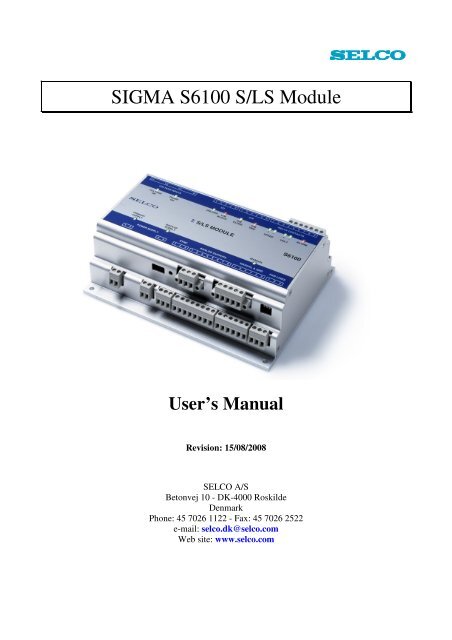
SIGMA <strong>S6100</strong> S/LS Module<br />
User’s <strong>Manual</strong><br />
Revision: 15/08/2008<br />
SELCO A/S<br />
Betonvej 10 - DK-4000 Roskilde<br />
Denmark<br />
Phone: 45 7026 1122 - Fax: 45 7026 2522<br />
e-mail: selco.dk@selco.com<br />
Web site: www.selco.com
SELCO A/S<br />
SIGMA <strong>S6100</strong> S/LS Module<br />
Table of Contents<br />
1 Preface .......................................................................................................................................... 6<br />
2 Isolation and Grounding ............................................................................................................... 7<br />
3 Function ....................................................................................................................................... 8<br />
3.1 Protection ............................................................................................................................. 8<br />
3.1.1 Voltage Establishment ..................................................................................................... 8<br />
3.1.2 Frequency Establishment ................................................................................................. 9<br />
3.1.3 Frequency Deviation Protection (Rate of Change of Frequency, ROCOF, df/dt relay) .. 9<br />
3.1.4 Start of standby generator in case of bus bar error (PM Start) ........................................ 9<br />
3.2 Frequency Stabilization...................................................................................................... 10<br />
3.3 Voltage Stabilization .......................................................................................................... 11<br />
3.4 Voltage Matching ............................................................................................................... 12<br />
3.5 Auto Synchronization ........................................................................................................ 13<br />
3.6 Check Synchronizer ........................................................................................................... 14<br />
3.7 Active Load Sharing .......................................................................................................... 15<br />
3.8 Reactive Load Sharing ....................................................................................................... 15<br />
4 System Preparation..................................................................................................................... 17<br />
4.1 CAN Bus Address .............................................................................................................. 17<br />
5 Installation .................................................................................................................................. 18<br />
6 Connection ................................................................................................................................. 19<br />
6.1 Power Supply ..................................................................................................................... 19<br />
6.1.1 Primary Supply .............................................................................................................. 19<br />
6.1.2 Backup Supply ............................................................................................................... 20<br />
6.2 Voltage Inputs .................................................................................................................... 20<br />
6.3 Sync .................................................................................................................................... 21<br />
6.4 I/O ...................................................................................................................................... 21<br />
6.4.1 Unload ............................................................................................................................ 22<br />
6.4.2 F/V Ctrl. Disable ............................................................................................................ 22<br />
6.4.3 Volt. In ........................................................................................................................... 22<br />
6.4.4 Freq. In ........................................................................................................................... 22<br />
6.4.5 C/B Close Block............................................................................................................. 22<br />
6.5 C/B ..................................................................................................................................... 22<br />
6.6 Relay Contacts ................................................................................................................... 23<br />
6.6.1 Speed +/- ........................................................................................................................ 23<br />
6.6.2 Volt +/- ........................................................................................................................... 23<br />
6.6.3 Alarm ............................................................................................................................. 23<br />
6.7 Analogue Outputs .............................................................................................................. 24<br />
6.8 <strong>Manual</strong> I/O & COM ........................................................................................................... 24<br />
Revision: 15-08-200815-08-2008 13:09:00 Page 2 of 52
SELCO A/S<br />
SIGMA <strong>S6100</strong> S/LS Module<br />
6.9 Par Lines ............................................................................................................................ 25<br />
6.10 RS485 ................................................................................................................................. 25<br />
6.11 CAN Bus ............................................................................................................................ 25<br />
6.12 Auxiliary I/O ...................................................................................................................... 26<br />
6.12.1 Engine Start ................................................................................................................ 27<br />
6.12.2 Engine Stop ................................................................................................................ 27<br />
6.12.3 DB Out ....................................................................................................................... 27<br />
6.12.4 DB In .......................................................................................................................... 27<br />
6.12.5 Engine Failed ............................................................................................................. 27<br />
6.12.6 Off Duty ..................................................................................................................... 27<br />
7 Configuration ............................................................................................................................. 28<br />
7.1 PID Regulation ................................................................................................................... 28<br />
7.1.1 Proportional control parameter (P) ................................................................................ 28<br />
7.1.2 Integrator control parameter (I)...................................................................................... 28<br />
7.1.3 Differentiator control parameter (D).............................................................................. 28<br />
7.2 Console Password .............................................................................................................. 28<br />
7.3 System Settings .................................................................................................................. 29<br />
7.3.1 Power-up Delay.............................................................................................................. 29<br />
7.4 Voltage OK Window ......................................................................................................... 29<br />
7.5 Speed Control ..................................................................................................................... 29<br />
7.5.1 Speed control enabled .................................................................................................... 30<br />
7.5.2 Mode .............................................................................................................................. 30<br />
7.5.3 Output............................................................................................................................. 30<br />
7.5.4 Minimum Pulse Duration ............................................................................................... 30<br />
7.5.5 Duty Cycle ..................................................................................................................... 30<br />
7.5.6 Analogue Signal ............................................................................................................. 30<br />
7.5.7 Voltage Range ................................................................................................................ 31<br />
7.5.8 Current Range ................................................................................................................ 31<br />
7.5.9 PWM Settings ................................................................................................................ 31<br />
7.6 Voltage Control .................................................................................................................. 31<br />
7.6.1 Voltage control enabled ................................................................................................. 31<br />
7.6.2 Mode .............................................................................................................................. 32<br />
7.6.3 Output............................................................................................................................. 32<br />
7.6.4 Minimum Pulse Duration ............................................................................................... 32<br />
7.6.5 Duty Cycle ..................................................................................................................... 32<br />
7.6.6 Analogue Signal ............................................................................................................. 32<br />
7.6.7 Voltage Range ................................................................................................................ 33<br />
7.6.8 Current Range ................................................................................................................ 33<br />
7.6.9 PWM Settings ................................................................................................................ 33<br />
7.7 Protection ........................................................................................................................... 33<br />
7.7.1 Voltage Establishment Protection .................................................................................. 33<br />
7.7.2 Frequency Establishment Protection .............................................................................. 34<br />
7.7.3 Frequency Deviation Protection ..................................................................................... 34<br />
Revision: 15-08-200815-08-2008 13:09:00 Page 3 of 52
SELCO A/S<br />
SIGMA <strong>S6100</strong> S/LS Module<br />
7.7.4 PM Start (pre-start of generator in case of bus bar fault)............................................... 35<br />
7.8 Frequency Stabilization...................................................................................................... 35<br />
7.8.1 Stability .......................................................................................................................... 35<br />
7.8.2 Deadband ....................................................................................................................... 35<br />
7.8.3 PID ................................................................................................................................. 35<br />
7.9 Auto Synchronizing ........................................................................................................... 36<br />
7.9.1 Check Synchonizer function .......................................................................................... 36<br />
7.9.2 Dead Bus Closure........................................................................................................... 36<br />
7.9.3 Stability .......................................................................................................................... 36<br />
7.9.4 Deadband ....................................................................................................................... 36<br />
7.9.5 Frequency Deviation ...................................................................................................... 37<br />
7.9.6 Phase Deviation.............................................................................................................. 37<br />
7.9.7 Circuit Breaker Close Time ........................................................................................... 37<br />
7.9.8 PID ................................................................................................................................. 37<br />
7.10 Active Load Sharing .......................................................................................................... 38<br />
7.10.1 Load Deviation ........................................................................................................... 38<br />
7.10.2 Stability ...................................................................................................................... 38<br />
7.10.3 Deadband ................................................................................................................... 38<br />
7.10.4 Parallel Lines.............................................................................................................. 38<br />
7.10.5 Ramp Time ................................................................................................................. 39<br />
7.10.6 Ramp Stability............................................................................................................ 39<br />
7.10.7 CB Trip Level ............................................................................................................ 39<br />
7.10.8 PID ............................................................................................................................. 39<br />
7.11 Voltage Stabilization .......................................................................................................... 40<br />
7.11.1 Stability ...................................................................................................................... 40<br />
7.11.2 Deadband ................................................................................................................... 40<br />
7.11.3 PID ............................................................................................................................. 40<br />
7.12 Voltage Matcher ................................................................................................................. 40<br />
7.12.1 Stability ...................................................................................................................... 41<br />
7.12.2 Deadband ................................................................................................................... 41<br />
7.12.3 PID ............................................................................................................................. 41<br />
7.13 Reactive Load Sharing ....................................................................................................... 41<br />
7.13.1 Load Deviation ........................................................................................................... 42<br />
7.13.2 Stability ...................................................................................................................... 42<br />
7.13.3 Deadband ................................................................................................................... 42<br />
7.13.4 Parallel Lines.............................................................................................................. 42<br />
7.13.5 Ramp Time ................................................................................................................. 42<br />
7.13.6 Ramp Stability............................................................................................................ 43<br />
7.13.7 CB Trip Level ............................................................................................................ 43<br />
7.13.8 PID ............................................................................................................................. 43<br />
7.14 I/O & Relays ...................................................................................................................... 43<br />
7.14.1 Alarm Relay Function ................................................................................................ 43<br />
7.14.2 C/B Trip Relay ........................................................................................................... 44<br />
7.14.3 Start Signal ................................................................................................................. 44<br />
7.14.4 Start Pulse .................................................................................................................. 44<br />
Revision: 15-08-200815-08-2008 13:09:00 Page 4 of 52
SELCO A/S<br />
SIGMA <strong>S6100</strong> S/LS Module<br />
7.14.5 Start Time Out ............................................................................................................ 44<br />
7.14.6 Stop Signal ................................................................................................................. 44<br />
7.14.7 Stop Pulse ................................................................................................................... 44<br />
7.14.8 Cool Down Time ........................................................................................................ 45<br />
7.15 Grid parallel operation/ power import ............................................................................... 45<br />
7.15.1 Power Import.............................................................................................................. 45<br />
7.15.2 Power Import Max ..................................................................................................... 45<br />
7.15.3 Power Import Mode ................................................................................................... 45<br />
7.15.4 Power Import Value ................................................................................................... 46<br />
7.16 Grid parallel operation/ power export ................................................................................ 46<br />
7.16.1 Power export .............................................................................................................. 46<br />
7.16.2 Power Export Max ..................................................................................................... 46<br />
7.16.3 Power Export Mode ................................................................................................... 46<br />
7.16.4 Power Export Value ................................................................................................... 47<br />
7.17 Powersource ....................................................................................................................... 47<br />
7.18 Dutyhour ............................................................................................................................ 47<br />
7.19 Priority ............................................................................................................................... 47<br />
7.20 RS485 ................................................................................................................................. 48<br />
7.21 Restoring to factory default configuration ......................................................................... 48<br />
8 Specifications ............................................................................................................................. 49<br />
Revision: 15-08-200815-08-2008 13:09:00 Page 5 of 52
SELCO A/S<br />
SIGMA <strong>S6100</strong> S/LS Module<br />
1 Preface<br />
The SELCO SIGMA <strong>S6100</strong> S/LS module provides integrated bus bar monitoring, frequency<br />
stabilization, voltage stabilization, check/automatic synchronisation and active/reactive load<br />
sharing. The <strong>S6100</strong> module relies upon the measurements and calculations broadcasted by its<br />
partner SELCO SIGMA S6000 IO/P module. The S6000 provides integrated protection, basic I/O<br />
and data acquisition. Finally, the <strong>S6100</strong> module will operate as an interface between the optional<br />
SELCO SIGMA S6600/S6610 Power Manager and the engine related signals (e.g. start/stop, engine<br />
fail etc.).<br />
Revision: 15-08-200815-08-2008 13:09:00 Page 6 of 52
SELCO A/S<br />
SIGMA <strong>S6100</strong> S/LS Module<br />
2 Isolation and Grounding<br />
In marine installations ground and common reference (COM) should not be connected together. In a<br />
ship installation the hull is the “ground”. Connecting any of the COM connections on any of the<br />
modules within a SIGMA system to ground (hull) or switchboard chassis may cause instability<br />
within the system.<br />
One, and only one, COM connection should to be made between SIGMA modules. This is<br />
preferably the COM connection of the CAN bus.<br />
The Primary and Backup 24 VDC supplies are isolated from the remaining <strong>electronic</strong>s of the<br />
module and therefore also from the common reference (COM). The negative poles of the 24 VDC<br />
supplies can be connected to the common reference (COM), provided that the either one, or both<br />
supplies serves as references for auxiliary relays driven by SIGMA open collector outputs. In this<br />
case the supplies negative poles should not be connected to ground (hull) or switchboard chassis.<br />
As a general rule:<br />
1. COM terminals should not be connected to ground (hull) or switchboard chassis.<br />
2. Negative poles of the primary and back-up supplies should not be connected to ground (hull)<br />
or switchboard chassis.<br />
3. Negative poles of the primary and back-up supplies and COM can be connected together,<br />
provided that the negative poles of the primary and back-up supplies are not connected to<br />
ground (hull) or switchboard chassis.<br />
Revision: 15-08-200815-08-2008 13:09:00 Page 7 of 52
SELCO A/S<br />
SIGMA <strong>S6100</strong> S/LS Module<br />
3 Function<br />
The <strong>S6100</strong> module provides integrated busbar monitoring as well as control for a single generator.<br />
The <strong>S6100</strong> includes a programmable control and output scheme, which makes it adaptable to almost<br />
any brand and type of speed governor. The same applies to the control of the automatic voltage<br />
regulator (AVR).<br />
3.1 Protection<br />
The <strong>S6100</strong> module provides three built-in protection functions. These protection functions operate<br />
from the 3 phased voltage measurements conducted by the <strong>S6100</strong> module, thus all three functions<br />
are intended for monitoring of the busbar. The protection functions can be configured with trip<br />
level(s). Delays are provided for filtering. The protection functions operate on RMS readings<br />
sampled over one or four periods (depending on the rated frequency).<br />
The C/B Trip LED will start flashing and the delay will begin counting the moment the trip level of<br />
the related protection function is exceeded. If the level is exceeded for the full duration of the delay,<br />
the C/B Trip LED will change to steady light and the circuit breaker will trip. Otherwise the LED<br />
will go off and the delay will reset.<br />
Unlike the generator protection functions provided in the S6000 module, no dedicated front folio<br />
LED’s and digital outputs (open collector outputs) are provided. Reset can be issued by and external<br />
input (C/B RESET at the related S6000 module) or from the keyboard of the optional S6500, S6600<br />
or S6610 module.<br />
The <strong>S6100</strong> module protects the external equipment by tripping the related breaker. The breaker is<br />
tripped through the built-in C/B trip relay. The C/B trip relay can be configured for normally deenergized<br />
or normally energized operation.<br />
3.1.1 Voltage Establishment<br />
The voltage establishment protection function can be enabled or disabled. If enabled the voltage<br />
establishment protection will trip the breaker in case the phase-phase voltages between any of the<br />
three phases becomes either too low or too high. The voltage establishment protection will act on<br />
the lowest or the highest of the three phase-phase voltage measurements, depending on whether the<br />
low or the high level is exceeded.<br />
U 12 U 23 U 31<br />
The trip level is configured as a percentage according to the nominal phase-phase voltage specified<br />
within the system configuration of the related S6000 module.<br />
U<br />
U<br />
12<br />
12<br />
orU<br />
orU<br />
23<br />
23<br />
orU<br />
orU<br />
31<br />
31<br />
Lower Level ⋅ NOMVOLT<br />
〈<br />
100<br />
Or<br />
Upper Level ⋅ NOMVOLT<br />
〉<br />
100<br />
Revision: 15-08-200815-08-2008 13:09:00 Page 8 of 52
SELCO A/S<br />
SIGMA <strong>S6100</strong> S/LS Module<br />
The delay is configured in seconds. Trip will occur only if the low or the high critical level is<br />
exceeded continuously for the duration of the delay.<br />
3.1.2 Frequency Establishment<br />
The frequency establishment protection function can be enabled or disabled. If enabled the<br />
frequency establishment protection will trip the breaker in case the busbar frequency becomes either<br />
too low or too high.<br />
The trip level is configured as a percentage according to the rated frequency specified within the<br />
system configuration of the related S6000 module.<br />
f<br />
f<br />
Lower Level ⋅ RATEFREQ<br />
〈<br />
100<br />
or<br />
Lower Level ⋅ RATEFREQ<br />
f 〉<br />
100<br />
The delay is configured in seconds. Trip will occur only if the low or the high critical level is<br />
exceeded continuously for the duration of the delay.<br />
3.1.3 Frequency Deviation Protection (Rate of Change of Frequency, ROCOF, df/dt relay)<br />
This function is only used for generators running in parallel with the grid.<br />
When running in parallel with the grid it is very important to detect short time interruptions of the<br />
grid. When the grid returns after a short interruption it can be expected to be out of synchronism.<br />
Thus a reconnection of the generator to the grid must be avoided.<br />
The FD function is doing that by measuring the change of frequency over time (rate of change of<br />
frequency).<br />
The module will measure the time between two zero crossings of the measurement voltage and<br />
calculate a frequency for each period.<br />
Slow changes in the grid frequency will not cause the unit to trip. However a rapid change in the<br />
frequency will cause the frequency deviation function to trip. Typical adjustment could be of 0.5 -<br />
1.5 Hz/sec.<br />
3.1.4 Start of standby generator in case of bus bar error (PM Start)<br />
This function can be used for reducing the black-out time in case of protection trips due to voltage<br />
or frequency errors.<br />
The function will use the frequency and voltage protection of the <strong>S6100</strong> Module as pre-alarm. Thus<br />
the C/B trip relay output of <strong>S6100</strong> should not be connected to the trip coil of the circuit breaker if<br />
this function should be used.<br />
Revision: 15-08-200815-08-2008 13:09:00 Page 9 of 52
SELCO A/S<br />
SIGMA <strong>S6100</strong> S/LS Module<br />
When the voltage or frequency protection function of the <strong>S6100</strong> module trips, the S6610 Power<br />
Manager Module will start up the next available stand by generator. The standby generator will start<br />
and establish rated frequency and voltage. However it will not synchronize to the bus bar, as there is<br />
a voltage or frequency problem there.<br />
After the voltage or frequency protection of the S6000 Module has tripped the breaker of the duty<br />
generator (and caused black-out on the bus bar), the standby generator will connect to the dead bus<br />
bar.<br />
For this function the voltage and frequency protection functions of <strong>S6100</strong> modules must be adjusted<br />
to the same level as the voltage and frequency protection functions of S6000 modules, however the<br />
delay must be shorter on the <strong>S6100</strong> modules for allowing the generators to power up before blackout.<br />
Otherwise the black-out time would be increased.<br />
The Bead bus closure (DB CLOSE) function must be enabled for this function.<br />
3.2 Frequency Stabilization<br />
The main purpose of the frequency stabilization function is to maintain the frequency at a fixed<br />
level, despite fluctuations in active load. The frequency stabilization is also able to provide quick<br />
and instant compensation should the frequency deviate from the preset level.<br />
Engines controlled by conventional governors operate with speed droop. The speed droop causes<br />
engine revolutions (and generator frequency) to decrease slightly when active load is applied to the<br />
generator. The frequency will typically only drop few percent between zero to full load.<br />
Engines controlled by <strong>electronic</strong> governors can be configured to operate in isynchronous mode.<br />
Isynchronous mode utilizes a speed feedback signal (e.g. from a flywheel pick-up) to compensate<br />
for the droop effect. Thus isynchronous mode provides zero droop (stable frequency with increase<br />
in active load). Electronic governors can also be configured to operate in droop mode with a certain<br />
percentage of droop.<br />
The frequency stabilization function of the <strong>S6100</strong> module will do much the same as the<br />
isynchronous feature of the <strong>electronic</strong> governor. However, there are some advantages to the <strong>S6100</strong><br />
frequency stabilization. First of all, it works with both conventional and <strong>electronic</strong> governors.<br />
Secondly, it provides seamless coexistence with other functions controlling the frequency (e.g.<br />
auto-synchronization and active load sharing). SELCO recommends that the governor is configured<br />
to operate with a few percent droop. This is to avoid a conflict between the <strong>S6100</strong> frequency<br />
regulation and the isynchronous compensation feature of the governor.<br />
The set point of the <strong>S6100</strong> frequency stabilization is defined by the rated frequency parameter<br />
(RATEDFREQ) of the partner S6000 module. The frequency stabilization function becomes active<br />
once the power-up delay has passed, provided that the function has not been disabled.<br />
The configuration of the frequency stabilization function depends on the chosen mode of speed<br />
control. The relay based speed control (Increase/decrease contact signals) is configured with<br />
stability and deadband, while the <strong>electronic</strong> control is set up with stability and PID parameters.<br />
The stability parameter determines the magnitude of the control signal as a function of the actual<br />
deviation in frequency (compared to rated frequency). A high stability setting provides fast<br />
Revision: 15-08-200815-08-2008 13:09:00 Page 10 of 52
SELCO A/S<br />
SIGMA <strong>S6100</strong> S/LS Module<br />
regulation, with the potential risk of over shoot and instability. A low stability setting provides<br />
accurate but slow regulation.<br />
The deadband parameter (only used with relay based speed control) determines the level of<br />
deviation required for the frequency stabilization to regulate. The system will not do any regulation<br />
as long as the frequency deviation is within the deadband. A low deadband setting results in<br />
continues fine tuning of the frequency, while a high deadband setting results in infrequent<br />
corrections at the expense of accuracy. The deadband is expressed as a percentage of the rated<br />
frequency.<br />
The PID parameters (only used with <strong>electronic</strong> speed control) works in conjunction with the<br />
stability parameter. Stability will affect the magnitude of the control signal when the deviation in<br />
frequency is relatively large, while the P-parameter determines the magnitude of the control signal<br />
when the deviation is small. Both stability and the P-parameter operate as a function of the<br />
frequency deviation. The I-parameter can be used to slow down the regulation (by increasing I).<br />
The D-parameter is seldom used and should be left at its default setting.<br />
Frequency stabilization can be disabled (together with voltage stabilization) by connecting the F/V<br />
CTRL. DISABLE input to COM. If disabled, it is important to ensure that a defined signal is<br />
applied to the external frequency and voltage control input (FREQ. IN and VOLT. IN).<br />
3.3 Voltage Stabilization<br />
The main purpose of the voltage stabilization function is to maintain the voltage at a fixed level,<br />
despite fluctuations in reactive load. The voltage stabilization must also be able to provide quick<br />
and instant compensation should the voltage deviate from the preset level.<br />
Alternators controlled by conventional voltage regulators operate with voltage droop. The voltage<br />
droop causes excitation (and alternator voltage) to decrease slightly when reactive load is applied to<br />
the generator. The voltage will typically only drop few percent between zero to full load.<br />
Alternators controlled by <strong>electronic</strong> voltage regulators can be configured to operate in isynchronous<br />
mode. Isynchronous mode utilizes a voltage feedback signal to compensate for the droop effect.<br />
Thus isynchronous mode provides zero droop (stable voltage with increase in reactive load).<br />
Electronic voltage regulators can also be configured to operate in droop mode with a certain<br />
percentage of droop.<br />
The voltage stabilization function of the <strong>S6100</strong> module will do much the same as the isynchronous<br />
feature of the <strong>electronic</strong> voltage regulator. However, there are some advantages to the <strong>S6100</strong><br />
voltage stabilization. First of all, it works with both conventional and <strong>electronic</strong> voltage regulators.<br />
Secondly, it provides seamless coexistence with other functions controlling the voltage (e.g. voltage<br />
matching and reactive load sharing). SELCO recommends that the voltage regulator is configured to<br />
operate with a few percent droop. This is to avoid a conflict between the <strong>S6100</strong> voltage regulation<br />
and the isynchronous compensation feature of the voltage regulator.<br />
The set point of the <strong>S6100</strong> voltage stabilization is defined by the nominal voltage parameter<br />
(NOMVOLT) of the partner S6000 module. The voltage stabilization function becomes active once<br />
the power-up delay has passed, provided that the function has not been disabled.<br />
Revision: 15-08-200815-08-2008 13:09:00 Page 11 of 52
SELCO A/S<br />
SIGMA <strong>S6100</strong> S/LS Module<br />
The configuration of the voltage stabilization function depends on the chosen mode of voltage<br />
control. The relay based voltage control (Increase/decrease contact signals) is configured with<br />
stability and deadband, while the <strong>electronic</strong> control is set up with stability and PID parameters.<br />
The stability parameter determines the magnitude of the control signal as a function of the actual<br />
deviation in voltage (compared to nominal voltage). A high stability setting provides fast regulation,<br />
with the potential risk of over shoot and instability. A low stability setting provides accurate but<br />
slow regulation.<br />
The deadband parameter (only used with relay based voltage control) determines the level of<br />
deviation required for the voltage stabilization to regulate. The system will not do any regulation as<br />
long as the voltage deviation is within the deadband. A low deadband setting results in continues<br />
fine tuning of the voltage, while a high deadband setting results in infrequent corrections at the<br />
expense of accuracy. The deadband is expressed as a percentage of the nominal voltage.<br />
The PID parameters (only used with <strong>electronic</strong> voltage control) works in conjunction with the<br />
stability parameter. Stability will affect the magnitude of the control signal when the deviation in<br />
voltage is relatively large, while the P-parameter determines the magnitude of the control signal<br />
when the deviation is small. Both stability and the P-parameter operate as a function of the voltage<br />
deviation. The I-parameter can be used to slow down the regulation (by increasing I). The D-<br />
parameter is seldom used and should be left at its default setting.<br />
Voltage stabilization can be disabled (together with frequency stabilization) by connecting the F/V<br />
CTRL. DISABLE input to COM. If disabled, it is important to ensure that a defined signal is<br />
applied to the external voltage and frequency control input (FREQ. IN and VOLT. IN).<br />
3.4 Voltage Matching<br />
The voltage matching function is used to match the voltage of the generator voltage to the busbar<br />
voltage. If enabled, voltage matching operates simultaneously with automatic synchronization. The<br />
voltage matching function works much like the automatic synchronization function; however<br />
voltage matching corrects the generator voltage instead of the frequency/phase deviation. The<br />
reference for the voltage matching function is the actual busbar voltage (not the nominal voltage).<br />
Do not mistake the voltage matching function with the voltage stabilization function. Voltage<br />
matching works only in conjunction with auto synchronization, while voltage stabilization work<br />
continuously (if enable). Furthermore, the reference for voltage matching function is the actual<br />
busbar voltage, as opposed to the nominal voltage which is reference for voltage stabilization.<br />
The configuration of the voltage matching function depends on the chosen mode of voltage control.<br />
The relay based voltage control (Increase/decrease contact signals) is configured with stability and<br />
deadband, while the <strong>electronic</strong> control is set up with stability and PID parameters.<br />
The stability parameter determines the magnitude of the control signal as a function of the actual<br />
deviation in voltage (compared to busbar voltage). A high stability setting provides fast regulation,<br />
with the potential risk of over shoot and instability. A low stability setting provides accurate but<br />
slow regulation.<br />
The deadband parameter (only used with relay based voltage control) determines the level of<br />
deviation required for the voltage matching to regulate. The system will not do any regulation as<br />
long as the voltage deviation is within the deadband. A low deadband setting results in continues<br />
Revision: 15-08-200815-08-2008 13:09:00 Page 12 of 52
SELCO A/S<br />
SIGMA <strong>S6100</strong> S/LS Module<br />
fine tuning of the voltage, while a high deadband setting results in infrequent corrections at the<br />
expense of accuracy. The deadband is expressed as a percentage of the nominal voltage.<br />
The PID parameters (only used with <strong>electronic</strong> voltage control) works in conjunction with the<br />
stability parameter. Stability will affect the magnitude of the control signal when the deviation in<br />
voltage is relatively large, while the P-parameter determines the magnitude of the control signal<br />
when the deviation is small. Both stability and the P-parameter operate as a function of the voltage<br />
deviation. The I-parameter can be used to slow down the regulation (by increasing I). The D-<br />
parameter is seldom used and should be left at the default setting.<br />
The purpose of the voltage matching function is typically just to bring the generator voltage within<br />
a reasonable range of the busbar voltage (e.g. +/-2 to +/-10%). Thus, voltage matching is in a way<br />
analogue to automatic synchronization, but without strict tolerances. The reference of the voltage<br />
matching function is defined by the VOLTOKWND parameter of the <strong>S6100</strong>.<br />
3.5 Auto Synchronization<br />
The auto synchronization function of the <strong>S6100</strong> module is used to automatically connect the<br />
generator to the busbar. Auto synchronization is initiated the moment the <strong>S6100</strong> module detects that<br />
a viable reference voltage exists on the busbar.<br />
The main purpose of the automatic synchronization function is to ensure quick and automatic<br />
connection of the generator to the busbar.<br />
A number of conditions must apply before the generator circuit breaker can be closed. First of all,<br />
the magnitude of the generator voltage must be equal or close to the magnitude of the busbar<br />
voltage (if voltage matching is enabled). Secondly, the frequency of the generator voltage must be a<br />
little higher or equal to the frequency of the busbar voltage. The third and last condition is that the<br />
phase deviation between the generator and busbar voltages must within a few degrees at the time of<br />
connection (breaker closure).<br />
The matching of the generator voltage is done by the voltage matching function described<br />
elsewhere in this document. Voltage matching is optional.<br />
The <strong>S6100</strong> auto synchronization function will alter the speed of the generator (by control of the<br />
speed governor) to obtain the required deviation in frequency and phase. Once all three conditions<br />
are true, the <strong>S6100</strong> module will issue the signal to close the circuit breaker.<br />
The auto synchronization function works differently depending on whether the <strong>S6100</strong> module is<br />
configured for speed control by relays (increase/decrease contact signals) or by <strong>electronic</strong> output.<br />
Governor control by the speed relay does not provide the facility to command and maintain exact<br />
frequency match and near zero phase deviation between the generator and busbar voltage.<br />
Synchronizing by speed relay is done by aiming for a small positive frequency deviation between<br />
the generator and busbar voltage, where after the closure signal is issued shortly before the<br />
generator voltage is expected to be in phase with the busbar voltage (to compensate for the circuit<br />
breaker make time).<br />
Auto synchronization by <strong>electronic</strong> speed control provides the possibility of bringing the generator<br />
voltage in phase with the busbar voltage and thereafter closing the breaker with near zero deviation<br />
in frequency and phase.<br />
Revision: 15-08-200815-08-2008 13:09:00 Page 13 of 52
SELCO A/S<br />
SIGMA <strong>S6100</strong> S/LS Module<br />
When speed is corrected by relay signals, the auto synchronization function is configured with<br />
stability and deadband. Stability defines the magnitude of the control signal as a function of the<br />
actual frequency deviation (between the generator and busbar voltage), while the deadband defines<br />
the frequency deviation required for the auto synchronizer to regulate. When operating by the speed<br />
relay the auto synchronizing function will alter the engine speed to obtain a small positive<br />
frequency deviation between the generator and busbar voltage. The automatic synchronizing<br />
function will then issue the signal to close the circuit breaker shortly before it expects zero phase<br />
deviation between the generator and busbar voltage. The closure signal is issued prior to the<br />
moment of zero phase deviation in order to compensate for the make time of the circuit breaker.<br />
The frequency deviation and circuit breaker closure time parameters are only used when the speed<br />
control is configured to operate by the speed relay. A low setting for the frequency deviation<br />
provides high accuracy, but will increase the time required to synchronize the generator. A high<br />
setting provides quick synchronization but might cause more wear and tear on the breaker contacts.<br />
The circuit breaker closure time must be set according to the breaker specification (breaker make<br />
time).<br />
The auto synchronization function is a bit more advanced when speed control is done by <strong>electronic</strong><br />
output. The speed feed back feature of an <strong>electronic</strong> governor makes it possible for the auto<br />
synchronization function to keep the generator in phase with the bus bar (without closing the<br />
breaker). In this case the synchronization will alter the frequency only to obtain close to zero phase<br />
deviation; where after the auto synchronization function can close the breaker at will. When<br />
configured for governor control by <strong>electronic</strong> output, the condition for closing the breaker is defined<br />
by tolerated phase deviation. A narrow phase deviation windows will provide accurate but slow<br />
synchronization, while a wider window provides speed at the cost of wear and tear on the breaker<br />
contacts.<br />
The PID parameters (only used with <strong>electronic</strong> voltage control) works in conjunction with the<br />
stability parameter. Stability will affect the magnitude of the control signal when the phase<br />
deviation is outside a +/-45 deg. window, while the P-parameter determines the magnitude of the<br />
control signal when the phase deviation is small. Both stability and the P-parameter operate as a<br />
function of the frequency and phase deviation. The I-parameter can be used to slow down the<br />
regulation (by increasing I). The D-parameter is seldom used and should be left at the default<br />
setting.<br />
The auto synchronization function can be configured to close on dead bus. The dead bus facility<br />
includes external I/O signals to prevent simultaneous dead bus connection of two or more<br />
generators.<br />
A synchronization time parameter is provided for the purpose of automation. An error will be issued<br />
through the LED of the C/B Close relays if the synchronization is not completed within the<br />
synchronization time.<br />
3.6 Check Synchronizer<br />
The check synchronizer function offers the possibility of closing the circuit breaker automatically<br />
during manual synchronization. The condition for closing the breaker is defined by tolerated phase<br />
deviation.<br />
Revision: 15-08-200815-08-2008 13:09:00 Page 14 of 52
SELCO A/S<br />
SIGMA <strong>S6100</strong> S/LS Module<br />
3.7 Active Load Sharing<br />
Active load sharing is initiated the moment that the circuit breaker is closed. The active load sharer<br />
function will increase/decrease engine speed (and thereby generator frequency) to make the<br />
generator take or release active current/load. The <strong>S6100</strong> module will balance the active current/load<br />
based on a DC voltage communicated through the kW parallel lines. This DC voltage can be<br />
adapted to suit other types of active load sharers (e.g. SELCO T4800 or T4400).<br />
The active load sharer is configured with load deviation, stability and deadband. The load deviation<br />
parameter is used to balance out small load deviations, which might be caused by inaccuracy within<br />
the external current transformers. Stability determines the magnitude of the speed control signal as a<br />
function of deviation in the balance of active current/load. A low stability setting will provide<br />
minimal overshoot and relatively slow balancing of the active current/load, while a high stability<br />
setting gives fast regulation with risk of overshoot (instability). The deadband simply defines the<br />
amount of load deviation required before the active load sharing kicks in.<br />
The kW parallel lines can be adjusted to operate with any voltage in the range of -6 to +6 V DC.<br />
The voltage range of the parallel lines is programmable in order to ensure compatibility with other<br />
types of SELCO load sharers.<br />
The active load sharing function includes the feature of unloaded trip. When activated (through the<br />
unload input) the active load sharer will decrease speed at a predefined rate (100 to 0% load). The<br />
<strong>S6100</strong> module will then trip the breaker automatically when the pre-programmed trip level is<br />
reached (provided that the reactive current/load has also been unloaded). The active load sharing<br />
function ramps up at with the same ramp time (when the unload signal is removed).<br />
The PID parameters (only used with <strong>electronic</strong> speed control) works in conjunction with the<br />
stability parameter. Stability will affect the magnitude of the control signal when the deviation in<br />
load is relatively large, while the P-parameter determines the magnitude of the control signal when<br />
the deviation is small. Both stability and the P-parameter operate as a function of the load deviation.<br />
The I-parameter can be used to slow down the regulation (by increasing I). The D-parameter is<br />
seldom used and should be left at the default setting. Please note that for active load sharing,<br />
deadband is also active with <strong>electronic</strong> speed control.<br />
The active load sharing function can be disabled.<br />
3.8 Reactive Load Sharing<br />
Reactive load sharing is initiated the moment that the circuit breaker is closed. The reactive load<br />
sharer will increase generator voltage to make the generator take reactive current/load, and decrease<br />
generator voltage to release reactive current/load. The <strong>S6100</strong> module will balance the reactive<br />
current/load based on a DC voltage communicated through the kVAr parallel lines. This DC voltage<br />
can be adapted to suit other types of reactive load sharers (e.g. SELCO T4900).<br />
The reactive load sharer is configured with load deviation, stability and deadband. The load<br />
deviation parameter is used to balance out small load deviations, which might be caused by<br />
inaccuracy within the external current transformers. Stability determines the magnitude of the<br />
voltage control signal as a function of deviation in the reactive current/load balance. A low stability<br />
setting will provide minimal overshoot and relatively slow balancing of the reactive current/load,<br />
while a high stability setting gives fast regulation with risk of overshoot and instability. The<br />
Revision: 15-08-200815-08-2008 13:09:00 Page 15 of 52
SELCO A/S<br />
SIGMA <strong>S6100</strong> S/LS Module<br />
deadband simply defines the amount of load deviation required before the reactive load sharing<br />
kicks in.<br />
The kVAr parallel lines can be adjusted to operate with any voltage in the range of -6 to +6 V DC.<br />
The voltage range of the parallel lines is programmable in order to ensure compatibility with other<br />
types of SELCO load sharers.<br />
The reactive load sharing function includes the feature of unloaded trip. When activated (through<br />
the unload input) the reactive load sharer will decrease speed at a predefined rate (100 to 0% load).<br />
The <strong>S6100</strong> module will then trip the breaker automatically when the pre-programmed trip level is<br />
reached (provided that the active current/load has also been unloaded). The reactive load sharing<br />
function ramps up at with the same ramp time (when the unload signal is removed).<br />
The PID parameters (only used with <strong>electronic</strong> voltage control) works in conjunction with the<br />
stability parameter. Stability will affect the magnitude of the control signal when the deviation in<br />
load is relatively large, while the P-parameter determines the magnitude of the control signal when<br />
the deviation is small. Both stability and the P-parameter operate as a function of the load deviation.<br />
The I-parameter can be used to slow down the regulation (by increasing I). The D-parameter is<br />
seldom used and should be left at the default setting. Please note that for reactive load sharing,<br />
deadband is also active with <strong>electronic</strong> speed control.<br />
The reactive load sharing function can be disabled.<br />
Revision: 15-08-200815-08-2008 13:09:00 Page 16 of 52
SELCO A/S<br />
SIGMA <strong>S6100</strong> S/LS Module<br />
4 System Preparation<br />
4.1 CAN Bus Address<br />
The 4-point dip-switch located on the right hand side of the S6000 module is used to set the CAN<br />
bus address. The CAN bus address is set as a binary value on 4 ON/OFF switches. Valid CAN bus<br />
address are 1 to 15.<br />
The CAN bus address should be set according to the generator reference number, thus the CAN<br />
address of an S6000 module and its partner <strong>S6100</strong> should be the same.<br />
It is advisable to assign address 1 to the first pair of S6000/<strong>S6100</strong> modules, number 2 to the second<br />
pair etc. S6500 user interface modules can be set to any address in the range 1 to 15. However, it is<br />
typically most practical to set a single S6500 to number 1. S6600 or S6610 Power Manager<br />
modules should be configured with address 1.<br />
Each pair of S6000 and <strong>S6100</strong> modules must be assigned a unique CAN bus address.<br />
The binary system works on the principle described below.<br />
• Switch 1 represents the decimal value 1<br />
• Switch 2 represents the decimal value 2<br />
• Switch 3 represents the decimal value 4<br />
• Switch 4 represents the decimal value 8<br />
As an example, the address 1 is assigned by setting switch 1 to ON and the remaining switches to<br />
OFF. Address 10 is assigned by setting switch 2 and 4 to ON and switch 1 and 3 to OFF. The<br />
decimal value corresponds to the sum of the values ON switch values.<br />
Revision: 15-08-200815-08-2008 13:09:00 Page 17 of 52
SELCO A/S<br />
SIGMA <strong>S6100</strong> S/LS Module<br />
5 Installation<br />
The <strong>S6100</strong> module is secured to the rear of the switch board using four 4 mm. (3/16”) screws. DIN<br />
rail mounting is not advisable due to the weight of the module.<br />
Please ensure that there is enough space around the module so that the plug-in terminals and RS232<br />
connector can be removed and reinserted. The length of the cables should also allow for the easy<br />
removal and insertion of the plug-in terminals. Access to the dip-switches located at the lower right<br />
hand corner of the unit might also be necessary.<br />
Revision: 15-08-200815-08-2008 13:09:00 Page 18 of 52
SELCO A/S<br />
SIGMA <strong>S6100</strong> S/LS Module<br />
6 Connection<br />
The <strong>S6100</strong> module is connected using plug-in terminals. The plug-in terminals provide safe and<br />
durable connection without sacrificing ease of installation and servicing.<br />
Wires should be good quality with a reasonable low internal resistance. It is advisable to use colour<br />
coding, as this makes trouble shooting and servicing far easier.<br />
Please ensure that all wires are stripped properly and that the screws of the plug-in terminal rest on<br />
the copper and not on the insulation. Insufficient wire stripping is a frequent cause for poor<br />
connections.<br />
6.1 Power Supply<br />
The <strong>electronic</strong>s of the <strong>S6100</strong> module is powered by two individual supplies, the primary and the<br />
backup supply. Both the primary and the backup supply operate on a nominal voltage of +24 V DC.<br />
The <strong>S6100</strong> module is capable of operating on both or either one of the two supplies. However, an<br />
alarm will be raised if the backup supply fails. Furthermore, each supply will tolerate wide<br />
variations in the supply voltage, as required by the marine classification societies.<br />
The primary supply occupies terminal 1 and 2 of the POWER SUPPLY plug-in connectors, while<br />
the backup supply occupies terminal 3 and 4.<br />
Terminal Description Signal Connection<br />
1 PRIMARY SUPPLY + +24 V DC Positive terminal of primary supply<br />
2 PRIMARY SUPPLY - -24 V DC Negative terminal of primary supply<br />
3 BACKUP SUPPLY + +24 V DC Positive terminal of backup supply<br />
4 BACKUP SUPPLY - - 24 V DC Negative terminal of backup supply<br />
The primary and backup supplies are isolated from each other and from the remaining <strong>electronic</strong>s of<br />
the module. This means that the supply reference terminals (terminal 2 and 4) have no connection to<br />
the modules COM terminals.<br />
The primary and backup supply is designed to cope with relative large voltage fluctuations, as<br />
required by the marine classification societies. However, please note that some marine classification<br />
societies require that the <strong>S6100</strong> module is powered by the generators voltage. This is easily done<br />
through adding an auxiliary +24 V DC supply powered by the generator voltage. Please make sure<br />
that the auxiliary supply is able to cope with the power demand.<br />
6.1.1 Primary Supply<br />
The switch board +24 V DC power supply system is typically used as the source of the primary<br />
supply.<br />
The front folio Primary Supply LED illuminates with a steady green light to indicate that the supply<br />
voltage is OK and within the limits of safe operation. A failure of the primary supply will cause the<br />
Primary Supply LED to turn off (after a brief delay).<br />
Revision: 15-08-200815-08-2008 13:09:00 Page 19 of 52
SELCO A/S<br />
SIGMA <strong>S6100</strong> S/LS Module<br />
6.1.2 Backup Supply<br />
The engine starter battery or the switch board +24 V DC backup power supply system is typically<br />
used as the source of the backup supply.<br />
The front folio Backup Supply LED illuminates with a steady green light to indicate that the supply<br />
voltage is OK and within the limits of safe operation. A failure of the backup supply will cause the<br />
backup Supply LED to turn off (after a brief delay) and the ALARM relay to de-energize.<br />
6.2 Voltage Inputs<br />
The AC voltages connect to the VOLTAGE INPUTS plug-in terminal. The <strong>S6100</strong> module supports<br />
both 3-wire and 4-wire power sources. As an example; busbars supplied by land based generators<br />
are typically 4-wired, while marine based generators typically use 3-wired.<br />
The voltage inputs can operate with high voltage (up to 690 VAC nominal), so precaution<br />
must be taken to avoid electrical shock and personal injury. Do not touch the VOLTAGE<br />
INPUTS plug-in terminal unless you are absolutely sure that power source is off (e.g. all the<br />
generator are stopped and blocked against starting).<br />
Voltages above 690 VAC are supported through use of external transformers (PT’s). When using<br />
PT’s it is important to ensure that the PT’s do not affect the phase of the voltage measurement.<br />
Phase shift in the PT’s will directly affect the calculation of the power factor, and thereby the<br />
calculation of active and reactive current/load.<br />
The <strong>S6100</strong> measures the individual phase-phase voltage between phases L1 and L2, L2 and L3 and<br />
L3 and L1. Phase-neutral voltages are also measured on 4-wire sources, while on 3-wire sources the<br />
phase-neutral voltages are estimated based on the assumption that loads are distributed equally<br />
among the three phases.<br />
Terminal Description Signal Connection<br />
L1 VOLTAGE INPUTS L1 AC voltage Busbar phase L1<br />
L2 VOLTAGE INPUTS L2 AC voltage Busbar phase L2<br />
L3 VOLTAGE INPUTS L3 AC voltage Busbar phase L3<br />
N VOLTAGE INPUTS N Neutral Busbar Neutral (optional)<br />
The three phases of the source L1, L2 and L3 should be connected to L1, L2 and L3 of the<br />
VOLTAGE INPUTS plug-in terminal. Intermediate 2 A slow-blow fuses should be inserted between<br />
the individual phases and the related voltage inputs. It is very important that the phases are<br />
connected in the correct order. Interchanging the phases will affect the measurements. It is very<br />
import that the three phases are connected to the corresponding terminals (phase 1 to L1, phase 2 to<br />
L2 and phase 3 to L3).<br />
Connection of the neutral terminal (terminal N) is optional. The neutral terminal (terminal N) is<br />
isolated from the remaining <strong>electronic</strong>s of the module. This means that the neutral terminal have no<br />
connection to the modules COM terminals.<br />
The VOLTAGE OK LED shows whether or not the voltage levels measured between each of the<br />
three phases are within limits. The reference is the nominal phase-phase voltage (NOMVOLT). The<br />
voltage levels are compared to the limits defined by the voltage OK window (VOLTOKWND) of<br />
Revision: 15-08-200815-08-2008 13:09:00 Page 20 of 52
SELCO A/S<br />
SIGMA <strong>S6100</strong> S/LS Module<br />
the configuration. The VOLTAGE OK LED will flash if generator is not on voltage and the busbar<br />
is live.<br />
The PHASE OK LED will ignite (steady green light) to indicate that the phase sequence is correct.<br />
However, the <strong>S6100</strong> module is not able to verify that the each phase is connected to the correct<br />
terminal. The <strong>S6100</strong> module cannot detect the difference between L1-L2-L3, L3-L1-L2 and L2-L3-<br />
L1. The <strong>S6100</strong> module can only verify that 120 degrees displacement exist between the three<br />
phases. The PHASE OK LED requires a “reasonable” level of voltage to become operational.<br />
The best way to ensure correct connection is to follow the wire all the way from the phase copper<br />
rail to the specific terminal within the VOLTAGE INPUTS plug-in connector.<br />
6.3 Sync<br />
The SYNC plug-in terminal provides a synchronization signal from the partner S6000 module.<br />
The synchronization signal is used by the <strong>S6100</strong> module to determine the zero crossing of the<br />
alternator voltage AC curves. This time critical information is required by the <strong>S6100</strong> module in<br />
order to do automatic synchronization.<br />
The synchronization signal is based on dedicated non-isolated RS485 interface. Thus, wiring must<br />
be done according to standard RS485 requirements.<br />
Terminal Description Signal Connection<br />
1 SYNC A RS485 A Terminal 1 of the partner S6000 SYNC<br />
2 SYNC B RS485 B Terminal 2 of the partner S6000 SYNC<br />
3 COM COM Terminal 3 of the partner S6000 SYNC<br />
The wires from terminal 1 and 2 should be twisted. A 150 ohm termination resistor must be placed<br />
between terminal 1 and 2 (directly at the plug-in terminal) to prevent signal reflections. Terminal 1<br />
must be connected to terminal 1 of the SYNC terminal on the partner S6000 module. Likewise<br />
terminal 2 must be connected to terminal 2 of the SYNC terminal on the partner S6000 module.<br />
Lastly, terminal 3 must be connected between the SYNC terminals of both modules. Terminal 3 will<br />
also serve as the common COM connection between the <strong>S6100</strong> and the S6000 module.<br />
6.4 I/O<br />
The I/O plug-in connector houses a number of digital and analogue inputs. The digital inputs works<br />
with negative reference, meaning the inputs are considered active when at COM level and inactive<br />
when left open (disconnected). The analogue signals use negative reference as well, which means<br />
that the analogue voltages (e.g. 0 - 1 V DC signals) must have COM as reference.<br />
Terminal Description Signal Connection<br />
1 UNLOAD NO contact to COM External switch, output or relay<br />
2 F/V CTRL. DISABLE NO contact to COM External switch, output or relay<br />
3 VOLT. IN DC voltage External output (-1 to 1 V DC)<br />
4 FREQ. IN DC voltage External output (-1 to 1 V DC)<br />
5 C/B CLOSE BLOCK NO contact to COM External switch, output or relay<br />
Revision: 15-08-200815-08-2008 13:09:00 Page 21 of 52
SELCO A/S<br />
SIGMA <strong>S6100</strong> S/LS Module<br />
6.4.1 Unload<br />
The UNLOAD input is used to do a ramped unload of the generator before the breaker is tripped.<br />
UNLOAD is typically initiated from an external switch. Unload starts once the UNLOAD signal is<br />
put to COM level. Disconnecting the UNLOAD signal causes reconnection of the generator, where<br />
after the load is applied by ramp.<br />
6.4.2 F/V Ctrl. Disable<br />
The F/V CTRL. DISABLE input is used to deactivate the voltage and frequency stabilization of the<br />
<strong>S6100</strong> module. The signal is considered active when the input is connected to COM level, and<br />
inactive when left open. The signal is typically used when the generator is operated in parallel with<br />
a shaft generator or the grid (power sources that determines the voltage and frequency), or when the<br />
voltage and frequency is controlled by external equipment (through the VOLT. IN and FREQ. IN<br />
analogue inputs).<br />
6.4.3 Volt. In<br />
The VOLT. IN input is an analogue input. The input can be used for external control of the generator<br />
voltage, provided that the F/V CTRL. DISABLE input is active (connected to COM). The analogue<br />
control signal must be a voltage between -1 and 1 V DC. The VOLT. IN input uses the COM<br />
terminal as reference. If not used, the VOLT. IN input should be connected to COM. This is<br />
especially important while the F/V CTRL. DISABLE input is active.<br />
6.4.4 Freq. In<br />
The FREQ. IN input is an analogue input. The input can be used for external control of the<br />
generator frequency, provided that the F/V CTRL. DISABLE input is active (connected to COM).<br />
The analogue control signal must be a voltage between -1 and 1 V DC. The FREQ. IN input uses<br />
the COM terminal as reference. If not used, the FREQ. IN input should be connected to COM. This<br />
is especially important while the F/V CTRL. DISABLE input is active.<br />
6.4.5 C/B Close Block<br />
The C/B CLOSE BLOCK can be used to disable the closure of the circuit breaker. The input is<br />
active when at COM level and inactive if left open. The C/B CLOSE BLOCK will not prevent auto<br />
synchronization, it will only prevent closure of the circuit breaker (activation of the C/B CLOSE<br />
relay). Thus, the C/B CLOSE BLOCK input is handy during test and commissioning (e.g. to test<br />
auto synchronization without closing the breaker).<br />
6.5 C/B<br />
The terminals of the relays intended for closing and tripping the circuit breaker (closing by auto<br />
synchronization and tripping by the busbar protection functions) is on the C/B plug-in connector.<br />
The built-in C/B close relay has two contact sets and is normally de-energized by default. The C/B<br />
trip relay has two contact sets and is also normally de-energized by default. Note that the C/B trip<br />
relay can be reconfigured to be normally energized operation.<br />
Terminal Description Signal Connection<br />
1 C/B CLOSE 1 Relay de-energized position Breaker remote close<br />
2 C/B CLOSE 2 Relay contact Signal source<br />
3 C/B CLOSE 3 Relay energized position Breaker remote close<br />
4 C/B TRIP 4 Relay de-energized position Breaker remote trip<br />
Revision: 15-08-200815-08-2008 13:09:00 Page 22 of 52
SELCO A/S<br />
SIGMA <strong>S6100</strong> S/LS Module<br />
5 C/B TRIP 5 Relay contact Signal source<br />
6 C/B TRIP 6 Relay energized position Breaker remote trip<br />
The C/B close relay connects to the remote close control input of the generator circuit breaker.<br />
Terminal 1 and 3 is typically not connected at the same time. Only one of this signals are taken to<br />
the breaker, depending on whether the C/B close relay is configured for normally de-energized or<br />
energized operation.<br />
The C/B trip relay connects to the remote trip control input of the generator circuit breaker.<br />
Terminal 4 and 6 is typically not connected at the same time. Only one of this signals are taken to<br />
the breaker, depending on whether the C/B trip relay is configured for normally de-energized or<br />
energized operation.<br />
6.6 Relay Contacts<br />
The RELAY CONTACTS plug-in connector includes the terminals of the two built-in toggling relays<br />
necessary to control relay operated speed governors and/or AVRs (or motor/<strong>electronic</strong><br />
potentiometers). The toggling relays can also be reconfigured for external frequency and/or voltage<br />
control. The last relay is the general alarm relay that will de-energize on system faults.<br />
Terminal Description Signal Connection<br />
1 SPEED + Relay position 1 Governor speed increase<br />
2 SPEED REF Relay contact (toggle) Governor ref<br />
3 SPEED - Relay position 2 Governor speed decrease<br />
4 VOLT + Relay position 1 AVR voltage increase<br />
5 VOLT REF Relay contact (toggle) AVR ref<br />
6 VOLT - Relay position 2 AVR voltage decrease<br />
7 ALARM 1 Relay de-energized position ALARM signal<br />
8 ALARM 2 Relay contact Signal source<br />
9 ALARM 3 Relay energized position All OK signal<br />
6.6.1 Speed +/-<br />
The speed relay is a toggling relay, which means that the relay contact is disconnected from both<br />
positions (1 and 2) when the speed/frequency regulation rests. When in operation, the <strong>S6100</strong><br />
module will toggle the relay between position 1 and 2. The duration of the relay pulses, and the rest<br />
time between pulses, will depend on the speed/frequency deviation as well as the configuration of<br />
the controlling function.<br />
6.6.2 Volt +/-<br />
The volt relay is a toggling relay, which means that the relay contact is disconnected from both<br />
positions (1 and 2) when the voltage regulation rests. When in operation, the <strong>S6100</strong> module will<br />
toggle the relay between position 1 and 2. The duration of the relay pulses, and the rest time<br />
between pulses, will depend on the voltage deviation as well as the configuration of the controlling<br />
function.<br />
6.6.3 Alarm<br />
The ALARM includes two contact sets. The alarm relays can only operate as a normally energized<br />
relay. This is to ensure that the ALARM relay will trip in case both supplies fail.<br />
Revision: 15-08-200815-08-2008 13:09:00 Page 23 of 52
SELCO A/S<br />
SIGMA <strong>S6100</strong> S/LS Module<br />
6.7 Analogue Outputs<br />
Two sets of analogue outputs are provided on-board of the <strong>S6100</strong> module. The analogue outputs are<br />
intended for direct control of <strong>electronic</strong> speed governors and/or AVR’s. Each of the two outputs can<br />
be individually configured to provide a DC voltage, current or PWM signal in relation to the speed<br />
or voltage control.<br />
Each analogue output can be configured to provide a DC voltage within the range of -10 to +10 V<br />
DC, a DC current within the range of 0 to 20 mA or a PWM signal with a default base frequency of<br />
500 Hz. The outputs are isolated from each other and from the remaining <strong>electronic</strong>s of the module.<br />
This means that the references of the outputs have no connection to each other or to the common<br />
reference (COM) of the module.<br />
Terminal Description Signal Connection<br />
1 ANALOG OUTPUT 1 VDC DC voltage Governor voltage input<br />
2 ANALOG OUTPUT 1 mA DC current Governor current input<br />
3 ANALOG OUTPUT 1 PWM PWM signal Governor PWM input<br />
4 ANALOG OUTPUT 1 REF reference (isolated) Governor reference<br />
5 ANALOG OUTPUT 2 VDC DC voltage AVR voltage input<br />
6 ANALOG OUTPUT 2 mA DC current AVR current input<br />
7 ANALOG OUTPUT 2 PWM PWM signal AVR PWM input<br />
8 ANALOG OUTPUT 2 REF reference (isolated) AVR reference<br />
It is important to note that each analogue output is protected against short-circuit by an internal 10<br />
kOhm resistor. The resistor is placed in series on the output terminal. The output resistor might<br />
affect the magnitude of the output signal if the internal resistance of the driven equipment is low.<br />
The principle of voltage division applies between the output resistor and the internal resistance of<br />
the driven equipment. Example: equipment with an internal resistance of only 10 kOhm would<br />
reduce a +10 V DC output voltage to +5 VDC. The two 10 kOhm resistors in series would make up<br />
a 1:2 voltage divider. Likewise, the amplitude of the PWM signal is limited to +8 V DC.<br />
Speed control is done either by the speed relay described elsewhere in this manual, or by the<br />
<strong>electronic</strong> outputs described above. The same applies to the voltage control. It is of cause possible<br />
to do speed control by <strong>electronic</strong> output, while doing voltage control by relays - and opposite. The<br />
mode of control and also be mixed among the parallel operating generators.<br />
6.8 <strong>Manual</strong> I/O & COM<br />
The <strong>S6100</strong> module can be switched into manual mode. When in manual, all control of both speed<br />
and voltage will stop - the speed and voltage relays will stop operation and the analogue outputs<br />
will stay at the present levels. Inputs are provided for manual external control of both speed and<br />
voltage.<br />
The C/B Trip Cause & COM plug-in terminal also houses a COM terminal.<br />
Terminal Description Signal Connection<br />
1 MANUAL CTRL. NO contact to COM External switch, output or relay<br />
2 SPEED INCR. NO contact to COM External push-button, output or relay<br />
3 SPEED DECR. NO contact to COM External push-button, output or relay<br />
4 VOLT INCR. NO contact to COM External push-button, output or relay<br />
Revision: 15-08-200815-08-2008 13:09:00 Page 24 of 52
SELCO A/S<br />
SIGMA <strong>S6100</strong> S/LS Module<br />
5 VOLT DECR. NO contact to COM External push-button, output or relay<br />
6 COM Common reference External reference<br />
The manual control signals has no function when the MANUAL CTRL. signal is active.<br />
6.9 Par Lines<br />
The signals of the parallel lines plug-in connector is used for balancing the active and reactive<br />
current/load between multiple <strong>S6100</strong> modules. The signal levels of the parallel lines can also be<br />
adapted to suit other types of SELCO load sharers (e.g. the SELCO T-series).<br />
Terminal Description Signal Connection<br />
1 KW BALANCE DC voltage KW BALANCE of other <strong>S6100</strong> modules<br />
2 COM Common reference COM of the other <strong>S6100</strong> modules<br />
3 KVAR BALANCE DC voltage KVAR BALANCE of other <strong>S6100</strong> modules<br />
6.10 RS485<br />
The <strong>S6100</strong> module includes an isolated RS485 interface.<br />
Terminal Description Signal Connection<br />
1 REF Reference (isolated) Reference of the RS485 bus<br />
2 A RS485 A A signal of the RS485 bus<br />
3 B RS485 B B signal of the RS485 bus<br />
It is important to note that the RS485 reference is isolated from the common COM of the module.<br />
The 3-wires RS485 bus is connected from module to module.<br />
A termination resistor of 150 ohm must be connected between terminal 2 and 3 at each end of the<br />
RS485 bus, preferably directly on the RS485 bus plug-in connector of the first RS485 slave and on<br />
the master.<br />
The maximum cable length is 1000 meters. The cable type should be 0.25 - 0.34 mm 2<br />
(AWG23/AWG22). Wires for A and B must be twisted (twisted-pair).<br />
6.11 CAN Bus<br />
The CAN bus is the backbone of the SIGMA system. The CAN bus carries all the measured and<br />
calculated parameters between the modules.<br />
Terminal Description Signal Connection<br />
1 COM Common reference Reference of the CAN bus<br />
2 CAN L CAN Lo (data) CAN Lo signal of the CAN bus<br />
3 - - -<br />
4 CAN H CAN Hi (data) CAN Hi signal of the CAN bus<br />
5 - - -<br />
Terminals 3 and 5 are not used.<br />
Revision: 15-08-200815-08-2008 13:09:00 Page 25 of 52
SELCO A/S<br />
SIGMA <strong>S6100</strong> S/LS Module<br />
The CAN L, CAN H and COM wires starts at one end of the total network, a termination resistor of<br />
124 Ohm is connected between CAN L and CAN H, preferably directly on the CAN bus plug-in<br />
connector. The cable is connected form SIGMA module to SIGMA module, without T connections.<br />
On the other end of the cable again a 124 Ohm terminator resistor is connected between the CAN<br />
lines.<br />
The maximum cable length is 40 meters. The cable type should be 0.25 - 0.34 mm 2<br />
(AWG23/AWG22). Wires for CAN Lo and CAN Hi must be twisted (twisted-pair). The reference<br />
COM must be interconnected between all modules and the cable should be shielded. The shield<br />
must only be connected to chassis/ground at one end.<br />
Every SIGMA module of the installation must be connected to the same CAN bus network. Third<br />
party CAN nodes may not be connected to the SIGMA CAN bus.<br />
6.12 Auxiliary I/O<br />
The auxiliary I/O plug-in connector houses general purpose I/O signals.<br />
The Inputs are considered activated when connected to COM, inactive when open.<br />
The outputs are open collector outputs. An open collector output works as an <strong>electronic</strong> contact to<br />
COM.<br />
Please note that the COM terminals are isolated from the power supplies. Therefore it is<br />
necessary to connect the minus of the power supply that supplies the equipment that is to be<br />
used with the open collector output, with one of the COM terminals of the SIGMA module.<br />
Example:<br />
In case a relay is to be activated by an open collector output, the minus of the power<br />
supply of this relay must be connected with one of the COM terminals of the SIGMA<br />
Module. This power supply must be 24V DC.<br />
Revision: 15-08-200815-08-2008 13:09:00 Page 26 of 52
SELCO A/S<br />
SIGMA <strong>S6100</strong> S/LS Module<br />
Terminal Description Signal Connection<br />
1 ENGINE START Open collector output Engine Controller start input<br />
2 ENGINE STOP Open collector output Engine Controller start input<br />
3 DB OUT Open collector output DB IN/OUT of other <strong>S6100</strong><br />
4 DB IN NO contact to COM DB IN/OUT of other <strong>S6100</strong><br />
5 ENGINE FAILED NO contact to COM Engine Controller fail output<br />
6 OFF DUTY NO contact to COM External switch, output or relay<br />
7 COM Common reference External reference<br />
6.12.1 Engine Start<br />
The Engine Start outputs can be controlled either from the RS485 MODBUS, or from the optional<br />
S6600 module. The signal is typically used to start the generator.<br />
6.12.2 Engine Stop<br />
The Engine Stop outputs can be controlled either from the RS485 MODBUS, or from the optional<br />
S6600 module. The signal is typically used to stop the generator.<br />
6.12.3 DB Out<br />
The DB Out signal is together with in DB In input. These two signals are used to prevent<br />
simultaneous closure to dead bus among multiple <strong>S6100</strong> modules. All DB Out and DB In terminals<br />
should be connected to a common point in the installation, preferably with wires of equal length.<br />
6.12.4 DB In<br />
The DB In input is together with in DB Out signal. These two signals are used to prevent<br />
simultaneous closure to dead bus among multiple <strong>S6100</strong> modules. All DB Out and DB In terminals<br />
should be connected to a common point in the installation, preferably with wires of equal length.<br />
6.12.5 Engine Failed<br />
The Engine Failed input is used by the optional S6600 module to determine if the generator has<br />
failed (e.g. on engine error).<br />
6.12.6 Off Duty<br />
The Off Duty input is used in conjunction with the optional S6600 module. The input is used as<br />
external request to set the generator off duty (e.g. for servicing).<br />
Revision: 15-08-200815-08-2008 13:09:00 Page 27 of 52
SELCO A/S<br />
SIGMA <strong>S6100</strong> S/LS Module<br />
7 Configuration<br />
The <strong>S6100</strong> module can be configured in three different ways. This section describes the<br />
configuration by RS232, as this method of configuration does not require the use of additional<br />
modules (the S6500 or S6600). The <strong>S6100</strong> module will however require a partner S6000 module, as<br />
the S6000 provides many of the basic parameters required by the <strong>S6100</strong>.<br />
The <strong>S6100</strong> module is delivered with a default configuration.<br />
7.1 PID Regulation<br />
The <strong>S6100</strong> module includes a total of six independent PID regulators. The PID regulators are only<br />
used when the modules is configured for <strong>electronic</strong> control (e.g. control by voltage, current or PWM<br />
signal). There is one PID controller for each of the following functions.<br />
• Frequency Stabilization<br />
• Voltage Stabilization<br />
• Auto-Synchronization<br />
• Voltage Matching<br />
• Active Load Sharing<br />
• Reactive Load Sharing<br />
7.1.1 Proportional control parameter (P)<br />
The proportional control parameter (P) determines the strength of the control signal as a function of<br />
the deviation (the difference between the actual value and the target value). Too much P will make<br />
the control unstable (hunting) and too little P will disable the control all together. The correct P<br />
setting will make the control responsive with no instability. I should be noted that Stability<br />
parameter works in a similar way. Stability operates as P when the deviation is large, while P is<br />
used at smaller deviations.<br />
7.1.2 Integrator control parameter (I)<br />
The integrator control parameter (I) works as a delay. It provides the “patience” of the system as it<br />
allows the system to wait for a response (change in the actual value) before it proceeds to step up<br />
the control signal. A large I will slow down the response of the system, but it may be necessary if<br />
the response of the speed control or voltage regulator is slow.<br />
7.1.3 Differentiator control parameter (D)<br />
This parameter is not used and should be left at its default setting.<br />
7.2 Console Password<br />
By default the RS232 console will operate in read only mode. The console can be switched to<br />
read/write mode by the enable command.<br />
ENABLE<br />
Revision: 15-08-200815-08-2008 13:09:00 Page 28 of 52
SELCO A/S<br />
SIGMA <strong>S6100</strong> S/LS Module<br />
Enable mode will prompt for a pin code. The default pin code is 0000.<br />
The console can be switched back to read only mode by the disable command.<br />
DISABLE<br />
Please note that the RS232 console pin code is separate for each module. Also, the RS232 pin code<br />
is independent from the menu pin code of the UI or PM module.<br />
7.3 System Settings<br />
The first thing to do is to configure the <strong>S6100</strong> to fit the controls of the generator (including the<br />
speed governor and the automatic voltage regulator).<br />
7.3.1 Power-up Delay<br />
The power-up delay determines the time between generator start-up (generator on voltage) and<br />
initiation of regulation (when the <strong>S6100</strong> will begin frequency and voltage stabilization). The powerup<br />
delay should be set so that the generator has time to “settle” before the <strong>S6100</strong> starts regulation of<br />
the speed and voltage.<br />
The power-up delay is expressed in seconds without decimals. The power-up delay is set by the<br />
following command. The resolution is 1 s.<br />
WRITE SYS POWERUPDELAY duration<br />
7.4 Voltage OK Window<br />
The <strong>S6100</strong> module needs to verify whether or not the busbar voltage is OK - that is whether or not<br />
the voltage level on each of the three phase-phase voltages are within limits.<br />
The voltage window defines the boundaries around (+/-) the nominal voltages which the module<br />
regards are acceptable for safe operation. The VOLTAGE OK LED will be lit provided that all<br />
three phase-phase voltage measurements are within the limits defined by the voltage window.<br />
The voltage window is configured by the following command. The resolution is 1 %.<br />
WRITE SYS VOLTOKWND <br />
7.5 Speed Control<br />
Speed control can be done using either increase/decrease relay signals or analogue output 1. The<br />
contact signals are well suited for control of either a conventional governor or a<br />
motorized/<strong>electronic</strong> potentiometer. Alternatively speed control can be done by analogue output 1<br />
using a voltage, current or PWM signal. The analogue speed output is intended for direct control of<br />
an <strong>electronic</strong> speed governor.<br />
The <strong>S6100</strong> speed regulator can reconfigured to operate as a frequency control signal (e.g. for<br />
remote control of other <strong>S6100</strong> modules through the FREQ IN input).<br />
A minimum pulse time defines the minimum closure time for the relay contacts; likewise min/max<br />
references define the operational range of analogue output. The <strong>S6100</strong> speed regulator is configured<br />
using the following commands.<br />
Revision: 15-08-200815-08-2008 13:09:00 Page 29 of 52
SELCO A/S<br />
SIGMA <strong>S6100</strong> S/LS Module<br />
7.5.1 Speed control enabled<br />
The speed control can be enabled or disabled by following command.<br />
WRITE SYS SPEEDCTRL ENABLED <br />
The choice can be YES or NO. The speed control function is required for frequency control,<br />
synchronizing and load sharing.<br />
In case the speed control is not used it should be disabled.<br />
7.5.2 Mode<br />
The mode of operation is either governor control or frequency output. The choice can be either<br />
GOVCTRL or FREQOUT.<br />
WRITE SYS SPEEDCTRL MODE <br />
7.5.3 Output<br />
The output can be either the speed increase/decrease relay contacts or analogue output 1. The choice<br />
can be set to SPEEDRELAY or ANAOUT1.<br />
WRITE SYS SPEEDCTRL OUT <br />
7.5.4 Minimum Pulse Duration<br />
The minimum pulse duration determines the duration of the shortest possible speed control pulse.<br />
The pulse duration setting is only in use when speed control is done by relays. Resolution is 1 ms.<br />
WRITE SYS SPEEDCTRL MINPULSE <br />
Setting the parameter too low will result in slow regulation, while a high setting will result in<br />
overshoot on the speed regulation.<br />
7.5.5 Duty Cycle<br />
The duty cycle parameter is only used when the speed control is done by relays. The duty cycle<br />
defines the minimum duration of the pulse and the rest time until the next pulse is issued.<br />
Resolution is 0.1 s.<br />
WRITE SYS SPEEDCTRL DUTYCYCLE <br />
Setting the duty cycle too low might result in overshoot and instability with a slow reacting<br />
(lagging) governor. A high setting might slow down the regulation.<br />
7.5.6 Analogue Signal<br />
The speed control by analogue output 1 can be configured to operate with either a DC voltage,<br />
current or a PWM signal. The type of output signal is set by the following command. Choice can be<br />
VOLT, CUR or PWM.<br />
WRITE SYS SPEEDCTRL ANAOUT SIGNAL <br />
The signal can be set to VOLT, CUR or PWM. The default setting is VOLT.<br />
Revision: 15-08-200815-08-2008 13:09:00 Page 30 of 52
SELCO A/S<br />
SIGMA <strong>S6100</strong> S/LS Module<br />
7.5.7 Voltage Range<br />
The voltage minimum and maximum references define the lower and upper limits of the voltage<br />
output signal. These parameters are only used when speed control is done by analogue output and<br />
when the analogue signal has been set to voltage. The resolution is 0.001 V DC.<br />
WRITE SYS SPEEDCTRL ANAOUT VOLTMIN <br />
WRITE SYS SPEEDCTRL ANAOUT VOLTMAX <br />
7.5.8 Current Range<br />
The current minimum and maximum references define the lower and upper limits of the current<br />
output signal. These parameters are only used when speed control is done by analogue output and<br />
when the analogue signal has been set to current. The resolution is 0.001 mA.<br />
WRITE SYS SPEEDCTRL ANAOUT CURMIN <br />
WRITE SYS SPEEDCTRL ANAOUT CURMAX <br />
7.5.9 PWM Settings<br />
The PWM settings describe the properties of the pulse-width modulated (PWM) output signal.<br />
These settings are only used when speed control is done by analogue output and when the analogue<br />
signal has been set to PWM.<br />
The resolution of the PWM base frequency is 1 Hz.<br />
WRITE SYS SPEEDCTRL PWMOUT FREQ <br />
The PWM maximum reference defines the amplitude of the PWM signal (0 VDC being the<br />
minimum reference). The resolution is 0.001 V DC.<br />
WRITE SYS SPEEDCTRL PWMOUT VOLTMAX <br />
7.6 Voltage Control<br />
Voltage control can be done using either increase/decrease relay signals or analogue output 2. The<br />
contact signals are well suited for control of either a conventional governor or a<br />
motorized/<strong>electronic</strong> potentiometer. Alternatively speed control can be done by analogue output 2<br />
using a voltage, current or PWM signal. The analogue voltage output is intended for direct control<br />
of an <strong>electronic</strong> AVR.<br />
The <strong>S6100</strong> voltage regulator can reconfigured to operate as a voltage control signal (e.g. for remote<br />
control of other <strong>S6100</strong> modules through the VOLT IN input).<br />
A minimum pulse time defines the minimum closure time for the relay contacts; likewise min/max<br />
references define the operational range of analogue output. The <strong>S6100</strong> voltage regulator is<br />
configured using the following commands.<br />
7.6.1 Voltage control enabled<br />
The voltage control can be enabled or disabled by following command.<br />
Revision: 15-08-200815-08-2008 13:09:00 Page 31 of 52
SELCO A/S<br />
SIGMA <strong>S6100</strong> S/LS Module<br />
WRITE SYS VOLTCTRL ENABLED <br />
The choice can be YES or NO. The voltage control function is required for voltage regulation,<br />
voltage matching and reactive load sharing.<br />
In case the voltage control is not used it should be disabled.<br />
7.6.2 Mode<br />
The mode of operation is either AVR control or voltage output. The choice can be either<br />
AVRCTRL or VOLTOUT.<br />
WRITE SYS VOLTCTRL MODE <br />
7.6.3 Output<br />
The output can be either the speed increase/decrease relay contacts or analogue output 2. The choice<br />
can be set to VOLTRELAY or ANAOUT2.<br />
WRITE SYS VOLTCTRL OUT <br />
7.6.4 Minimum Pulse Duration<br />
The minimum pulse duration determines the duration of the shortest possible voltage control pulse.<br />
The pulse duration setting is only in use when voltage control is done by relays. Resolution is 1 ms.<br />
WRITE SYS VOLTCTRL MINPULSE <br />
Setting the parameter too low will result in slow regulation, while a high setting will result in<br />
overshoot on the voltage regulation.<br />
7.6.5 Duty Cycle<br />
The duty cycle parameter is only used when the voltage control is done by relays. The duty cycle<br />
defines the minimum duration of the pulse and the rest time until the next pulse is issued.<br />
Resolution is 0.1 s.<br />
WRITE SYS VOLTCTRL DUTYCYCLE <br />
Setting the duty cycle too low might result in overshoot and instability with a slow reacting<br />
(lagging) AVR. A high setting might slow down the regulation.<br />
7.6.6 Analogue Signal<br />
The voltage control by analogue output 2 can be configured to operate with either a DC voltage,<br />
current or a PWM signal. The type of output signal is set by the following command. Choice can be<br />
VOLT, CUR or PWM.<br />
WRITE SYS VOLTCTRL ANAOUT SIGNAL <br />
The signal can be set to VOLT, CUR or PWM. The default setting is VOLT.<br />
Revision: 15-08-200815-08-2008 13:09:00 Page 32 of 52
SELCO A/S<br />
SIGMA <strong>S6100</strong> S/LS Module<br />
7.6.7 Voltage Range<br />
The voltage minimum and maximum references define the lower and upper limits of the voltage<br />
output signal. These parameters are only used when voltage control is done by analogue output and<br />
when the analogue signal has been set to voltage. The resolution is 0.001 V DC.<br />
WRITE SYS VOLTCTRL ANAOUT VOLTMIN <br />
WRITE SYS VOLTCTRL ANAOUT VOLTMAX <br />
7.6.8 Current Range<br />
The current minimum and maximum references define the lower and upper limits of the current<br />
output signal. These parameters are only used when voltage control is done by analogue output and<br />
when the analogue signal has been set to current. The resolution is 0.001 mA.<br />
WRITE SYS VOLTCTRL ANAOUT CURMIN <br />
WRITE SYS VOLTCTRL ANAOUT CURMAX <br />
7.6.9 PWM Settings<br />
The PWM settings describe the properties of the pulse-width modulated (PWM) output signal.<br />
These settings are only used when voltage control is done by analogue output and when the<br />
analogue signal has been set to PWM.<br />
The resolution of the PWM base frequency is 1 Hz.<br />
WRITE SYS VOLTCTRL PWMOUT FREQ <br />
The PWM maximum reference defines the amplitude of the PWM signal (0 VDC being the<br />
minimum reference). The resolution is 0.001 V DC.<br />
WRITE SYS VOLTCTRL PWMOUT VOLTMAX <br />
7.7 Protection<br />
Voltage and frequency establish protection is provided for monitoring the bus bar.<br />
7.7.1 Voltage Establishment Protection<br />
The voltage establishment protection can be enabled or disabled. This is done by the following<br />
command. The choice can be set to either YES or NO.<br />
WRITE PROTECT VE ENABLED <br />
The lower trip level is expressed in percent without decimals. The trip level refers to the nominal<br />
phase-phase voltage. The lower trip level is set by the following command. Resolution is 1 %.<br />
WRITE PROTECT VE LOWLEVEL <br />
The upper trip level is expressed in percent without decimals. The trip level refers to the nominal<br />
voltage. The upper trip level is set by the following command. Resolution is 1 %.<br />
Revision: 15-08-200815-08-2008 13:09:00 Page 33 of 52
SELCO A/S<br />
SIGMA <strong>S6100</strong> S/LS Module<br />
WRITE PROTECT VE UPLEVEL <br />
The lower delay is expressed in seconds with one decimal. The delay is set by the following<br />
command. Resolution is 0.1 s.<br />
WRITE PROTECT VE LOWDELAY <br />
The upper delay is expressed in seconds with one decimal. The delay is set by the following<br />
command. Resolution is 0.1 s.<br />
WRITE PROTECT VE UPDELAY <br />
7.7.2 Frequency Establishment Protection<br />
The frequency establishment protection can be enabled or disabled. This is done by the following<br />
command. The choice can be set to either YES or NO.<br />
WRITE PROTECT FE ENABLED <br />
The lower trip level is expressed in percent without decimals. The trip level refers to the nominal<br />
phase-phase voltage. The lower trip level is set by the following command. Resolution is 1 %.<br />
WRITE PROTECT FE LOWLEVEL <br />
The upper trip level is expressed in percent without decimals. The trip level refers to the nominal<br />
voltage. The upper trip level is set by the following command. Resolution is 1 %.<br />
WRITE PROTECT FE UPLEVEL <br />
The lower delay is expressed in seconds with one decimal. The delay is set by the following<br />
command. Resolution is 0.1 s.<br />
WRITE PROTECT FE LOWDELAY <br />
The upper delay is expressed in seconds with one decimal. The delay is set by the following<br />
command. Resolution is 0.1 s.<br />
WRITE PROTECT FE UPDELAY <br />
7.7.3 Frequency Deviation Protection<br />
The frequency deviation protection can be enabled or disabled. This is done by the following<br />
command. The choice can be set to either YES or NO.<br />
WRITE PROTECT FD ENABLED <br />
The trip level is expressed in hertz per second with one decimal. The lower trip level is set by the<br />
following command. Resolution is 0.1 Hz.<br />
WRITE PROTECT FD LEVEL <br />
Revision: 15-08-200815-08-2008 13:09:00 Page 34 of 52
SELCO A/S<br />
SIGMA <strong>S6100</strong> S/LS Module<br />
7.7.4 PM Start (pre-start of generator in case of bus bar fault)<br />
The PM START function can be enabled or disabled. This is done by the following command. The<br />
choice can be set to either YES or NO. In default configuration this function is disabled.<br />
WRITE PROTECT PMSTART <br />
7.8 Frequency Stabilization<br />
The frequency stabilization feature ensures that the generator frequency is kept at a fixed level. The<br />
frequency control facility uses the rated frequency as its reference. The frequency stabilization<br />
feature will compensate for frequency deviations caused by change in active load.<br />
7.8.1 Stability<br />
The stability parameter determines the response of the frequency stabilization. The response<br />
determines how much signal is provided to the governor and thereby how quickly the frequency is<br />
stabilized as a function of the actual deviation in frequency. A low setting will result in slow but<br />
accurate stabilization, while a high setting provide fast regulation with the potential risk of<br />
overshoot and instability. Stability is expressed as a number without decimals. Stability is set by the<br />
following command. Resolution is 1.<br />
WRITE FREQSTAB STABILITY <br />
7.8.2 Deadband<br />
The deadband parameter is only used when the speed adjustment is configured to operate with the<br />
speed relay. The deadband parameter determines the responsive range of the frequency stabilization<br />
feature. The frequency stabilization function will only attempt to correct the frequency if it is<br />
outside the deadband. A deadband which is too narrow will cause constant fine tuning of the<br />
frequency, while an overly wide deadband will cause deviation according to the reference (rated<br />
frequency). The deadband is expressed in percent with one decimal and is set by the following<br />
command. Resolution is 0.1 %.<br />
WRITE FREQSTAB DEADBAND <br />
7.8.3 PID<br />
The PID parameters are only used when the speed adjustment is configured to operate with the<br />
analogue output signal. The P (proportional) parameter is expressed as a gain factor and is set by the<br />
following command. Resolution is 0.1.<br />
WRITE FREQSTAB PID P <br />
The I (integral) parameter is expressed in milliseconds and is set by the following command.<br />
Resolution is 1 ms.<br />
WRITE FREQSTAB PID I <br />
The D (differential) parameter is expressed in milliseconds and is set by the following command.<br />
Resolution is 1 ms.<br />
WRITE FREQSTAB PID D <br />
Revision: 15-08-200815-08-2008 13:09:00 Page 35 of 52
SELCO A/S<br />
SIGMA <strong>S6100</strong> S/LS Module<br />
7.9 Auto Synchronizing<br />
The configuration of the auto synchronizing function depends on whether the speed control is done<br />
by the speed relay (increase/decrease contacts) or by analogue output 1. The difference exists due to<br />
the fact that synchronization by conventional and <strong>electronic</strong> speed governor works according to<br />
different principles. A generator controlled by an <strong>electronic</strong> governor can be locked in phase, while<br />
this is not possible with conventional speed control.<br />
The main difference in the configuration is that the relay driven operation is configured with<br />
frequency difference and circuit breaker close time, while the analogue control is configured with<br />
close angle.<br />
7.9.1 Check Synchonizer function<br />
The check synchronizer function offers the possibility of closing the circuit breaker automatically<br />
during manual synchronization. The condition for closing the breaker is defined by tolerated phase<br />
deviation.<br />
The function can be disabled or enabled. Choice can be YES or NO.<br />
WRITE AUTOSYNC CHKSYNC <br />
In default configuration this function is disabled.<br />
7.9.2 Dead Bus Closure<br />
The dead bus closure function provides the possibility of closing the circuit breaker when no<br />
voltage exists between either one of the three phases (on the busbar). The dead bus closure function<br />
requires the connection of the DB IN and DB OUT I/O signals. These two signals are used to<br />
prevent simultaneous closure by two or more S/LS modules. The dead bus closure function can be<br />
disabled or enabled. Choice can be YES or NO.<br />
WRITE AUTOSYNC DBCLOSE <br />
7.9.3 Stability<br />
Stability defines the response of the auto synchronizer. The auto synchronizer will alter the<br />
frequency in order to obtain the required frequency and phase deviation, or in case of <strong>electronic</strong><br />
governor control, in order to obtain zero frequency and phase deviation. The auto synchronizer<br />
changes the frequency by increasing or decreasing engine speed through control of the speed<br />
governor. The magnitude of the governor control signals, compared to the actual deviation in<br />
frequency, is determined by the synchronizer stability parameter. Too much stability provides<br />
accurate but slow synchronization, while too little stability introduces the risk of overshoot and<br />
instability. Stability is expressed as a number without decimals. Stability is set by the following<br />
command. Resolution is 1.<br />
WRITE AUTOSYNC STABILITY <br />
7.9.4 Deadband<br />
The deadband parameter is only used when the speed adjustment is configured to operate with with<br />
the speed relay. The deadband parameter determines the responsive range of the auto synchronizer.<br />
The synchronizer will only attempt to correct the frequency while is outside the deadband<br />
Revision: 15-08-200815-08-2008 13:09:00 Page 36 of 52
SELCO A/S<br />
SIGMA <strong>S6100</strong> S/LS Module<br />
(compared to the frequency on the bus bar). A deadband which is too narrow will cause constant<br />
fine tuning of the frequency, while an overly wide deadband will cause deviation according to the<br />
reference. The deadband is expressed in percent with one decimal and is set by the following<br />
command. Resolution is 0.1 %.<br />
WRITE AUTOSYNC DEADBAND <br />
7.9.5 Frequency Deviation<br />
The frequency deviation parameter is only used when the speed adjustment is configured to the<br />
speed relay. This parameter describes the tolerated frequency deviation at breaker closure. Setting<br />
this parameter to high might stress the breaker and generator. A low setting will however make the<br />
synchronization procedure a lengthy process. The frequency deviation is expressed in Hz with one<br />
decimal. The parameter is set by the following command. Resolution is 0.1 Hz.<br />
WRITE AUTOSYNC FREQDEV <br />
7.9.6 Phase Deviation<br />
The phase deviation is only used when the speed adjustment is configured to use analogue output 1.<br />
This parameter describes the tolerated phase deviation for closing the circuit breaker. The phase<br />
deviation is expressed in degrees without decimals. The parameter is set by the following command.<br />
Resolution is 1 deg.<br />
WRITE AUTOSYNC PHASEDEV <br />
7.9.7 Circuit Breaker Close Time<br />
The circuit breaker closure time is only used when the speed control is configured to the speed<br />
relay. This parameter determines when the actual closure signal is issued to the circuit breaker<br />
(through the C/B close relay). Auto synchronization by relay control requires the existence of a<br />
small positive frequency deviation, thus in order to compensate for the breaker closure time it is<br />
necessary to issue the closure signal just before phase accordance is expected to occur. The circuit<br />
breaker closure time is expressed in milliseconds without decimals. The parameter is set by the<br />
following command. Resolution is 1 ms.<br />
WRITE AUTOSYNC CBCLOSETIME <br />
7.9.8 PID<br />
The PID parameters are only used when the speed adjustment is configured to operate with an<br />
analogue output signal. The P (proportional) parameter is expressed as a gain factor and is set by the<br />
following command. Resolution is 1.0.<br />
WRITE AUTOSYNC PID P <br />
The I (integral) parameter is expressed in milliseconds and is set by the following command.<br />
Resolution is 1 ms.<br />
WRITE AUTOSYNC PID I <br />
The D (differential) parameter is expressed in milliseconds and is set by the following command.<br />
Resolution is 1 ms.<br />
Revision: 15-08-200815-08-2008 13:09:00 Page 37 of 52
SELCO A/S<br />
SIGMA <strong>S6100</strong> S/LS Module<br />
WRITE AUTOSYNC PID D <br />
7.10 Active Load Sharing<br />
The S/LS module moves active load to and from the generator by increasing or decreasing the speed<br />
(and generator frequency). The active load balance is communicated two a set of “parallel lines”<br />
that operates with a pre-configured DC voltage. The active load sharer includes a bonus feature of<br />
de-loaded trip together with programmable ramp-up and ramp-down of active load.<br />
7.10.1 Load Deviation<br />
The load deviation parameter can be used to fine tune the balance of the active load sharing.<br />
Imbalance might occur due to inaccuracy within the current transformers etc. The load deviation is<br />
set according to ideal zero deviation. The parameter is expressed as a percentage without decimals.<br />
The parameter has reference to perfect balance. Resolution is 1%.<br />
WRITE ACTLS LOADDEV <br />
7.10.2 Stability<br />
Stability defines the response of the active load sharer. The active load sharer will alter the active<br />
load (by altering the frequency) in order to obtain the required load balance. The active load sharer<br />
changes the active load level by increasing or decreasing engine speed through the governor. The<br />
magnitude of the governor control signals, compared to the actual deviation in active load, is<br />
determined by the stability parameter. Too mush stability provides accurate but slow load sharing,<br />
while too little stability introduces risk of overshoot and instability. Stability is expressed as a<br />
number without decimals. Stability is set by the following command. Resolution is 1.<br />
WRITE ACTLS STABILITY <br />
7.10.3 Deadband<br />
The deadband parameter determines the responsive range of the active load sharer. The active load<br />
sharer will only attempt to outbalance the deviation in active load when deviation falls outside the<br />
deadband (compared to the pre-configured load deviation). A deadband which is too narrow will<br />
cause constant fine tuning of the active load balance, while an overly wide deadband will cause<br />
deviation according to the reference. The deadband is expressed in percent with one decimal and is<br />
set by the following command. Resolution is 0.1 %.<br />
WRITE ACTLS DEADBAND <br />
7.10.4 Parallel Lines<br />
The parallel settings of the lines minimum and maximum DC voltage determines the voltage level<br />
used to communicate balance in active load between multiple S/LS modules. The voltage range can<br />
be changed to obtain compability with e.g. SELCO T4400 or T4800 load sharers. However the<br />
default range should be maintained to provide the best possible dynamics. Resolution is 0.1 V DC.<br />
WRITE ACTLS PARLINES VOLTMIN <br />
WRITE ACTLS PARLINES VOLTMAX <br />
Revision: 15-08-200815-08-2008 13:09:00 Page 38 of 52
SELCO A/S<br />
SIGMA <strong>S6100</strong> S/LS Module<br />
7.10.5 Ramp Time<br />
Ramp time defines how quickly the load sharer takes or releases active load. The active load is<br />
ramped-up when the active load sharing is enabled. This happened after synchronization or after the<br />
unload signal has been released. The load is ramped-down when the unload signal is enabled. The<br />
parameters defines the time to go from zero to full load (nominal load), or opposite. The ramp time<br />
parameter is expressed in seconds without decimals. Resolution is 1 s.<br />
WRITE ACTLS RAMPTIME <br />
7.10.6 Ramp Stability<br />
Ramp stability defines the response of the active load sharer during ramp-up and ramp-down. The<br />
active load sharer will alter the active load (by altering the frequency) in order to obtain the required<br />
ramp ratio. The active load sharer changes the active load level by increasing or decreasing engine<br />
speed through the governor. The magnitude of the governor control signals, compared to the actual<br />
deviation in active load, is determined by the ramp stability parameter. Too mush stability provides<br />
accurate but slow correction of the ramp ratio, while too little stability introduces risk of overshoot<br />
and instability. Ramp stability is expressed as a number without decimals. Ramp stability is set by<br />
the following command. Resolution is 1.<br />
WRITE ACTLS RAMPSTABILITY <br />
7.10.7 CB Trip Level<br />
CB trip level defines the level of active load where, following an unload, the circuit breaker should<br />
be automatically tripped. The CB Trip level works in AND relation to the reactive CB Trip level.<br />
The CB trip level is expressed in percent without decimals. The trip level is set according to full<br />
load (nominal load). Resolution is 1%.<br />
WRITE ACTLS CBTRIPLEVEL <br />
7.10.8 PID<br />
The PID parameters are only used when the speed adjustment is configured to operate with an<br />
analogue output signal. The P (proportional) parameter is expressed as a gain factor and is set by the<br />
following command. Resolution is 0.1.<br />
WRITE ACTLS PID P <br />
The I (integral) parameter is expressed in milliseconds and is set by the following command.<br />
Resolution is 1 ms.<br />
WRITE ACTLS PID I <br />
The D (differential) parameter is expressed in milliseconds and is set by the following command.<br />
Resolution is 1 ms.<br />
WRITE ACTLS PID D <br />
Revision: 15-08-200815-08-2008 13:09:00 Page 39 of 52
SELCO A/S<br />
SIGMA <strong>S6100</strong> S/LS Module<br />
7.11 Voltage Stabilization<br />
The voltage control feature ensures that the generator voltage is kept at a fixed level. The voltage<br />
control facility uses the nominal phase-phase voltage as reference. The voltage stabilization feature<br />
will compensate for voltage deviations caused by change in reactive load.<br />
7.11.1 Stability<br />
The stability parameter determines the response of the voltage stabilisation. The response<br />
determines how much signal is provided to the AVR and thereby how quickly the voltage is<br />
stabilized as a function of the actual deviation in voltage. A low setting will result in slow but<br />
accurate stabilization, while a high setting provide fast regulation with a potential risk of overshoot<br />
and instability. Stability is expressed as a number without decimals. Stability is set by the following<br />
command. Resolution is 1.<br />
WRITE VOLTSTAB STABILITY <br />
7.11.2 Deadband<br />
The deadband parameter is only used when the voltage adjustment is configured to operate with the<br />
voltage relay. The deadband parameter determines the responsive range of the voltage control<br />
feature. The voltage control function will only attempt to stabilize the voltage if it is outside the<br />
deadband. A deadband which is too narrow will cause constant fine tuning of the voltage, while an<br />
overly wide deadband will cause deviation according to the reference. The deadband is expressed in<br />
percent with one decimal and is set by the following command. Resolution is 0.1.<br />
WRITE VOLTSTAB DEADBAND <br />
7.11.3 PID<br />
The PID parameters are only used when the voltage adjustment is configured to operate with the<br />
analogue output signal. The P (proportional) parameter is expressed as a gain factor and is set by the<br />
following command. Resolution is 0.1.<br />
WRITE VOLTSTAB PID P <br />
The I (integral) parameter is expressed in milliseconds and is set by the following command.<br />
Resolution is 0.1 ms.<br />
WRITE VOLTSTAB PID I <br />
The D (differential) parameter is expressed in milliseconds and is set by the following command.<br />
Resolution is 0.1 ms.<br />
WRITE VOLTSTAB PID D <br />
7.12 Voltage Matcher<br />
The S/LS module includes voltage matching, which can be enabled or disabled. Voltage matching<br />
can automatically bring the voltage within the range specified by the Voltage OK Window. The<br />
S/LS module will control the voltage by the AVR. If enabled, voltage matching will be conducted<br />
before automatic synchronization is initiated. The voltage matching function is configured with<br />
stability and deadband. Stability determines the response of the voltage control signal as a function<br />
Revision: 15-08-200815-08-2008 13:09:00 Page 40 of 52
SELCO A/S<br />
SIGMA <strong>S6100</strong> S/LS Module<br />
of voltage deviation, while the deadband defines the active area of regulation. PID parameters are<br />
provided for tuning the voltage matcher when it controls an <strong>electronic</strong> AVR.<br />
7.12.1 Stability<br />
The stability parameter determines the response of the voltage matching function. The response<br />
determines how much signal is provided to the AVR and thereby how quickly the voltage is<br />
brought into the permitted operational area (compared to the Voltage OK Window). A low setting<br />
will result in slow but accurate correction, while a high setting provide fast correction with a<br />
potential risk of overshoot and instability. Stability is expressed as a number without decimals.<br />
Stability is set by the following command. Resolution is 1.<br />
WRITE VOLTMATCH STABILITY <br />
7.12.2 Deadband<br />
The deadband parameter is only used when the voltage adjustment is configured to operate with<br />
relays. The deadband parameter controls the accuracy of the voltage matching function. The voltage<br />
matching function will only attempt to correct the voltage if the is outside the voltage OK window,<br />
plus/minus the deadband. A deadband which is too narrow will cause constant fine tuning of the<br />
AVR, while an overly wide deadband will cause an inaccurate setting. The deadband is expressed in<br />
percent with one decimal and is set by the following command. Resolution is 0.1 %.<br />
WRITE VOLTMATCH DEADBAND <br />
7.12.3 PID<br />
The PID parameters are only used when the voltage adjustment is configured to operate with an<br />
analogue output signal. The P (proportional) parameter is expressed as a gain factor and is set by the<br />
following command. Resolution is 0.1.<br />
WRITE VOLTMATCH PID P <br />
The I (integral) parameter is expressed in milliseconds and is set by the following command.<br />
Resolution is 1 ms.<br />
WRITE VOLTMATCH PID I <br />
The D (differential) parameter is expressed in milliseconds and is set by the following command.<br />
Resolution is 1 ms.<br />
WRITE VOLTMATCH PID D <br />
7.13 Reactive Load Sharing<br />
The S/LS module moves reactive load to and from the generator by increasing or decreasing the<br />
voltage. The reactive load balance is communicated two a set of “parallel lines” that operates with a<br />
pre-configured DC voltage. The load sharer includes a bonus feature of programmable ramp-up and<br />
ramp-down of reactive load.<br />
Revision: 15-08-200815-08-2008 13:09:00 Page 41 of 52
SELCO A/S<br />
SIGMA <strong>S6100</strong> S/LS Module<br />
7.13.1 Load Deviation<br />
The load deviation parameter can be used to fine tune the balance of the reactive load sharing.<br />
Imbalance might occur due to inaccuracy within the current transformers etc. The load deviation is<br />
set according to ideal zero deviation. The parameter is expressed as a percentage without decimals.<br />
The parameter has reference to perfect balance. Resolution is 1%.<br />
WRITE REACTLS LOADDEV <br />
7.13.2 Stability<br />
Stability defines the response of the reactive load sharer. The reactive load sharer will alter the<br />
reactive load (by altering the voltage) in order to obtain the required load balance. The reactive load<br />
sharer changes the reactive load level by increasing or decreasing generator voltage through the<br />
AVR. The magnitude of the AVR control signals, compared to the actual deviation in reactive load,<br />
is determined by the stability parameter. Too mush stability provides accurate but slow load<br />
sharing, while too little stability introduces risk of overshoot and instability. Stability is expressed<br />
as a number without decimals. Stability is set by the following command. Resolution is 1.<br />
WRITE REACTLS STABILITY <br />
7.13.3 Deadband<br />
The deadband parameter determines the responsive range of the reactive load sharer. The reactive<br />
load sharer will only attempt to outbalance the deviation in reactive load when deviation falls<br />
outside the deadband (compared to the pre-configured load deviation). A deadband which is too<br />
narrow will cause constant fine tuning of the reactive load balance, while an overly wide deadband<br />
will cause deviation according to the reference. The deadband is expressed in percent with one<br />
decimal and is set by the following command. Resolution is 0.1 %.<br />
WRITE REACTLS DEADBAND <br />
7.13.4 Parallel Lines<br />
The parallel settings of the lines minimum and maximum DC voltage determines the voltage level<br />
used to communicate balance in active load between multiple S/LS modules. The voltage range can<br />
be changed to obtain compability with e.g. SELCO T4900 VAr load sharer. However the default<br />
range should be maintained to provide the best possible dynamics. Resolution is 0.1 V DC.<br />
WRITE REACTLS PARLINES VOLTMIN <br />
WRITE REACTLS PARLINES VOLTMAX <br />
7.13.5 Ramp Time<br />
Ramp time defines how quickly the load sharer takes or releases reactive load. The reactive load is<br />
ramped-up when the reactive load sharing is enabled. This happened after synchronization or after<br />
the unload signal has been released. The load is ramped-down when the unload signal is enabled.<br />
The parameters defines the time to go from zero to full load (nominal load), or opposite. The ramp<br />
time parameter is expressed in seconds without decimals. Duration is 1 s.<br />
WRITE REACTLS RAMPTIME <br />
Revision: 15-08-200815-08-2008 13:09:00 Page 42 of 52
SELCO A/S<br />
SIGMA <strong>S6100</strong> S/LS Module<br />
7.13.6 Ramp Stability<br />
Ramp stability defines the response of the reactive load sharer during ramp-up and ramp-down. The<br />
reactive load sharer will alter the reactive load (by altering the voltage) in order to obtain the<br />
required ramp ratio. The reactive load sharer changes the reactive load level by increasing or<br />
decreasing voltage through the AVR. The magnitude of the AVR control signals, compared to the<br />
actual deviation in reactive load, is determined by the ramp stability parameter. Too mush stability<br />
provides accurate but slow correction of the ramp ratio, while too little stability introduces risk of<br />
overshoot and instability. Ramp stability is expressed as a number without decimals. Ramp stability<br />
is set by the following command. Resolution is 1.<br />
WRITE REACTLS RAMPSTABILITY <br />
7.13.7 CB Trip Level<br />
CB trip level defines the level of reactive load where, following an unload, the circuit breaker<br />
should be automatically tripped. The CB Trip level works in AND relation to the active CB Trip<br />
level. The CB trip level is expressed in percent without decimals. The trip level is set according to<br />
full load (nominal load). Resolution is 1 %.<br />
WRITE REACTLS CBTRIPLEVEL <br />
7.13.8 PID<br />
The PID parameters are only used when the voltage adjustment is configured to operate with an<br />
analogue output signal. The P (proportional) parameter is expressed as a gain factor and is set by the<br />
following command. Resolution is 0.1.<br />
WRITE REACTLS PID P <br />
The I (integral) parameter is expressed in milliseconds and is set by the following command.<br />
Resolution is 1 ms.<br />
WRITE REACTLS PID I <br />
The D (differential) parameter is expressed in milliseconds and is set by the following command.<br />
resolution is 1 ms.<br />
WRITE REACTLS PID D <br />
7.14 I/O & Relays<br />
This part of the configuration determines the functions and properties of the relays. The relays can<br />
be configured for normal de-energized or energized operation. Non-latching relays can also be<br />
configured with regard to reset delay.<br />
7.14.1 Alarm Relay Function<br />
The alarm relay can be configured to signal either system alarm or system and protection alarms.<br />
The relay function is set by the following command. The choice can be either SYS or SYSPROT.<br />
WRITE IORELAYS ALARMRELAYFUNC <br />
Revision: 15-08-200815-08-2008 13:09:00 Page 43 of 52
SELCO A/S<br />
SIGMA <strong>S6100</strong> S/LS Module<br />
7.14.2 C/B Trip Relay<br />
The C/B trip relay can be configured for normally de-energized or normally energized operation.<br />
The command to set this property is as follows. Choice can be ND or NE.<br />
WRITE IORELAYS CBTRIP CONTACT <br />
7.14.3 Start Signal<br />
This function is only active in connection with a S6600 or S6610 PM Module. The output is the<br />
start signal to the engine. It can be programmed to be continous (active as long as the engine is<br />
running) or a pulse signal.<br />
WRITE IORELAYS STARTSIGNAL <br />
Choice can be CONT or PULSE, default is pulse.<br />
7.14.4 Start Pulse<br />
This function is only active in connection with a S6600 or S6610 PM Module. In case the start<br />
signal is programmed as a pulse signal, the length of the pulse can be programmed by following<br />
command:<br />
WRITE IORELAYS STARTPULSE <br />
The range can be between 100ms and 5000ms. The resolution is 1ms and default is 1000ms<br />
7.14.5 Start Time Out<br />
This function is only active in connection with a S6600 or S6610 PM Module. After <strong>S6100</strong> has<br />
issued the start command to the generator it expects the voltage to be built up within the Start Time<br />
Out delay. If the generator does not build up voltage, <strong>S6100</strong> will generate an ENGINE START<br />
ERROR and the Power Manager Module will issue a start command to the next stand by generator.<br />
The length of this delay can be defined by following command:<br />
WRITE IORELAYS STARTTIMEOUT <br />
The range of this delay is between 0 and 5000s. The resolution is 1s and the default setting is 10s.<br />
7.14.6 Stop Signal<br />
This function is only active in connection with a S6600 or S6610 PM Module. The output is the<br />
stop signal to the engine. It can be programmed to be continous (active as long as the engine is<br />
stopped) or a pulse signal.<br />
WRITE IORELAYS STOPSIGNAL <br />
Choice can be CONT or PULSE, default is pulse.<br />
7.14.7 Stop Pulse<br />
This function is only active in connection with a S6600 or S6610 PM Module. In case the stop<br />
signal is programmed as a pulse signal, the length of the pulse can be programmed by following<br />
command:<br />
Revision: 15-08-200815-08-2008 13:09:00 Page 44 of 52
SELCO A/S<br />
SIGMA <strong>S6100</strong> S/LS Module<br />
WRITE IORELAYS STOPPULSE <br />
The range can be between 100ms and 5000ms. The resolution is 1ms and default is 1000ms<br />
7.14.8 Cool Down Time<br />
This function is only active in connection with a S6600 or S6610 PM Module.<br />
With this command the cool down time for the engine can be defined. The cool down time is the<br />
time the engine continues running after the circuit breaker has been tripped.<br />
The length of the cool down time can be programmed by following command:<br />
WRITE IORELAYS COOLDOWN <br />
The range of this delay is between 0 and 10000s. The resolution is 1s and the default setting is 5s.<br />
7.15 Grid parallel operation/ power import<br />
During grid parallel operation it is necessary to assign one pair S6000/ <strong>S6100</strong> to the grid. This unit<br />
must be connected across the tie breaker. The parameters mentioned under are only relevant for the<br />
<strong>S6100</strong> module assigned to the grid. For more detailed information regarding grid parallel operation<br />
please see manual “<strong>S6100</strong> Paralleling with grid or shaft” on the SELCO internet page.<br />
7.15.1 Power Import<br />
In case power shall be imported from the grid into the system, the power import function has to be<br />
enabled. This can be done by following command:<br />
WRITE SYS PWRIMPORT ENABLED <br />
The choice can be YES or NO, default is NO.<br />
7.15.2 Power Import Max<br />
With this command the maximum limit of power to be imported can be defined as a percentage of<br />
the capacity defined in the S6000 module assigned to the grid.<br />
WRITE SYS PWRIMPORT MAX <br />
The range is between 1 and 100, the resolution is 1% and the default value is 100%.<br />
7.15.3 Power Import Mode<br />
With this command the import mode can be defined:<br />
WRITE SYS PWRIMPORT MODE <br />
The choice can be FIXED or PEAK, default is FIXED.<br />
“FIXED” means that a fixed amount of power (defined by the command PWRIMPORT VALUE )<br />
will be imported from the grid.<br />
Revision: 15-08-200815-08-2008 13:09:00 Page 45 of 52
SELCO A/S<br />
SIGMA <strong>S6100</strong> S/LS Module<br />
“PEAK” means that all load above a certain value (defined by the command PWRIMPORT<br />
VALUE ) will be imported from the grid.<br />
7.15.4 Power Import Value<br />
With power import mode configured to FIXED this command defines how much power will be<br />
imported from the grid. The amount of power is expressed as a percentage of the rated power<br />
defined in the S6000 module assigned to the grid.<br />
With power import mode configured to PEAK this command defines the maximum load of the<br />
connected generators. This max load level is expressed as a percentage of the rated power of the<br />
connected generators and defined by the command PWRIMPORT VALUE. In case the installation<br />
requires more power than defined by this parameter, all excess power will be imported from the<br />
grid.<br />
WRITE SYS PWRIMPORT VALUE <br />
The value can be between 1 and 100, the resolution is 1% and default is 25%.<br />
7.16 Grid parallel operation/ power export<br />
During grid parallel operation it is necessary to assign one pair S6000/ <strong>S6100</strong> to the grid. This unit<br />
must be connected across the tie breaker. The parameters mentioned under are only relevant for the<br />
<strong>S6100</strong> module assigned to the grid. For more detailed information regarding grid parallel operation<br />
please see manual “<strong>S6100</strong> Paralleling with grid or shaft” on the SELCO internet page.<br />
7.16.1 Power export<br />
In case power shall be exported to the grid, the power export function has to be enabled. This can be<br />
done by following command:<br />
WRITE SYS PWREXPORT ENABLED <br />
The choice can be YES or NO, default is NO.<br />
7.16.2 Power Export Max<br />
With this command the maximum limit of power to be exported can be defined as a percentage of<br />
the capacity defined in the S6000 module assigned to the grid.<br />
WRITE SYS PWREXPORT MAX <br />
The range is between 1 and 100, the resolution is 1% and the default value is 100%.<br />
7.16.3 Power Export Mode<br />
With this command the export mode can be defined:<br />
WRITE SYS PWREXPORT MODE <br />
The choice can be FIXED or EXCESS, default is FIXED.<br />
“FIXED” means that a fixed amount of power (defined by the command PWREXPORT VALUE )<br />
will be exported to the grid.<br />
Revision: 15-08-200815-08-2008 13:09:00 Page 46 of 52
SELCO A/S<br />
SIGMA <strong>S6100</strong> S/LS Module<br />
“EXCESS” means that all power above a certain value (defined by the command PWREXPORT<br />
VALUE) will be exported to the grid.<br />
7.16.4 Power Export Value<br />
With power export mode configured to FIXED this command defines how much power will be<br />
exported to the grid. The amount of power is expressed as a percentage of the rated power defined<br />
in the S6000 module assigned to the grid.<br />
With power export mode configured to EXCESS this command defines the load of the connected<br />
generators. This load level is expressed as a percentage of the rated power of the connected<br />
generators and defined by the command PWREXPORT VALUE. In case the installation requires<br />
less power than defined by this parameter, all excess power will be exported to the grid.<br />
WRITE SYS PWREXPORT VALUE <br />
The value can be between 1 and 100, the resolution is 1% and default is 25%.<br />
7.17 Powersource<br />
This command defines if the <strong>S6100</strong> module is assigned to an auxiliary generator (or any power<br />
source that allows the <strong>S6100</strong> to control its speed), a shaft generator or the grid.<br />
WRITE SYS POWERSOURCE <br />
The choice can be AUXILIARY, SHAFT OR GRID, default is AUXILIARY.<br />
7.18 Dutyhour<br />
This command defines the running hours of the generator set. It is used in connection with the<br />
S6600 or S6610 PM Module for the Duty Hour start stop scheme.<br />
When the generator is running, <strong>S6100</strong> will count the running hourson this parameter. It is possible<br />
to assign the amount of running hours. This is necessary when the control equipment of an older<br />
generatyor will be replaced by <strong>S6100</strong> or after a firmware upgrade of the <strong>S6100</strong> module.<br />
The amount of running hours can be defined by following command:<br />
WRITE SYS DUTYHOUR <br />
The value is the amount of running hours. The range can be between 0 and 999999. The resolution<br />
is 1h and the default value is 0.<br />
7.19 Priority<br />
This parameter is only relevant in connection with the S6600 or S6610 PM Module. It defines the<br />
start/ stop priority for the generators.<br />
The priority can be assigned by following command:<br />
WRITE SYS PRIORITY <br />
The value can be between 1 and 15, the resolution is 1 and default is 1.<br />
Revision: 15-08-200815-08-2008 13:09:00 Page 47 of 52
SELCO A/S<br />
SIGMA <strong>S6100</strong> S/LS Module<br />
7.20 RS485<br />
The RS485 communication interface can be configured with regard to MODBUS slave address,<br />
baud rate, data bit, parity and stop bits. It is important to ensure that the address is unique on the bus<br />
and that the remaining parameters are set according to specifications.<br />
The MODBUS slave address is set by the following command.<br />
WRITE RS485 ADDRESS <br />
The data transmission rate is defined by the baud rate, which is set as follows.<br />
WRITE RS485 BAUDRATE <br />
The parity can be set by the following command.<br />
WRITE RS485 PARITY <br />
The number of data bits is set as follows.<br />
WRITE RS485 DATABITS <br />
The number of stop bits is set as follows.<br />
WRITE RS485 STOPBITS <br />
In case the data from the MODBUS master is send irregular (compared to MODBUS specification)<br />
it is possible to adjust a delay for detection of the end of the MODBUS frame send by the master.<br />
Following command is used for that:<br />
WRITE RS485 TXDELAY [0-2552] (0)<br />
The range is between 0 and 2552ms. Default is 0ms.<br />
In case the frames send by the MODBUS master comply with the MODBUS specifications it is not<br />
necessary to change this parameter (it can remain in default setting).<br />
7.21 Restoring to factory default configuration<br />
The factory default configuration can be restored at any time by issuing the command:<br />
WRITE SYS SETUPDEFAULT YES<br />
The default configuration is then restored after the power to the module has been turned off and on.<br />
Revision: 15-08-200815-08-2008 13:09:00 Page 48 of 52
SELCO A/S<br />
SIGMA <strong>S6100</strong> S/LS Module<br />
8 Specifications<br />
Primary Supply:<br />
+24 V DC (-30 % / +30 %) Isolated<br />
Backup Supply:<br />
+24 V DC (-30 % / +30 %) Isolated<br />
Busbar phase-phase voltage (BPPV): 63 to 690 VA C (-2 % / +2 %) three phased, default 400 V AC<br />
Busbar phase-neutral voltage (BPNV): BPPV / √3 (measured only with neutral connection)<br />
Frequency Stabilization<br />
On/Off Control:<br />
By F/V Disable input<br />
Conventional Speed Control<br />
Stability:<br />
Pulse duration as a function deviation from rated frequency (GRF)<br />
1 to 100, default 10<br />
Deadband:<br />
+/- offset around rated frequency (GRF) where no regulation occurs to<br />
0.1 % to 20.0 %, default 0.2 %<br />
Electronic Speed Control<br />
Stability:<br />
Ramp rate used before optimized PID control is released<br />
1 to 100, default 10<br />
P: Proportional control, 1.0 to 20.0, default 4.0<br />
I: Integral control, 0 to 100 ms, default 10 ms<br />
D: Derivative control, 0 to 100 ms, default 1 ms<br />
Voltage Stabilization<br />
On/Off Control:<br />
Conventional AVR<br />
Stability:<br />
Deadband:<br />
Electronic AVR<br />
Stability:<br />
By F/V Disable input<br />
Pulse duration as a function deviation from nominal voltage (GPPV)<br />
1 to 100, default 5<br />
+/- offset around nominal voltage (GPPV) where no regulation occurs,<br />
0.1 % to 20.0 %, default 0.2 %<br />
Ramp rate used before optimized PID control is released<br />
1 to 100, default 5<br />
P: Proportional control, 1.0 to 20.0, default 1.0<br />
I: Integral control, 0 to 100 ms, default 10 ms<br />
D: Derivative control, 0 to 100 ms, default 1 ms<br />
Voltage Matching<br />
On/Off Control:<br />
Conventional AVR<br />
Stability:<br />
Deadband:<br />
Electronic AVR<br />
Stability:<br />
By configuration<br />
Pulse duration as a function deviation from actual busbar voltage<br />
1 to 100, default 5<br />
+/- offset around actual busbar voltage, where no regulation occurs,<br />
0.1 % to 20.0 %, default 5.0 %<br />
Ramp rate used before optimized PID control is released<br />
1 to 100, default 5<br />
P: Proportional control, 1.0 to 20.0, default 1.0<br />
I: Integral control, 0 to 100 ms, default 10 ms<br />
D: Derivative control, 0 to 100 ms, default 1 ms<br />
Auto-Synchronization<br />
Dead Bus Closure:<br />
On/Off Control:<br />
C/B Close Disable:<br />
Conventional Speed Control<br />
Stability:<br />
Deadband:<br />
3 phase (configurable)<br />
By <strong>Manual</strong> input<br />
By C/B Block input<br />
Pulse duration as a function deviation from busbar frequency<br />
1 to 100, default 1<br />
+/- offset around deviation from busbar frequency, where no regulation<br />
occurs, 0.1 to 20.0 %, default 1.0 %<br />
Revision: 15-08-200815-08-2008 13:09:00 Page 49 of 52
SELCO A/S<br />
SIGMA <strong>S6100</strong> S/LS Module<br />
closed<br />
Frequency Deviation:<br />
C/B Close time:<br />
Electronic Speed Control<br />
Stability:<br />
Phase Deviation:<br />
Active Load Sharing<br />
On/Off Control:<br />
Load Deviation:<br />
Tolerated frequency deviation from busbar voltage when breaker is<br />
+0.1 to +10.0 Hz, default +0.2 Hz<br />
Anticipated closure time of the circuit breaker<br />
1 to 1000 ms, default 80 ms<br />
Ramp rate used before optimized PID control is released<br />
1 to 100, default 1<br />
Tolerated phase deviation from busbar voltage when breaker is closed<br />
1 to 15 degrees, default 5 degrees<br />
P: Proportional control, 1.0 to 20.0, default 6.0<br />
I: Integral control, 0 to 100 ms, default 10 ms<br />
D: Derivative control, 0 to 100 ms, default 1 ms<br />
Parallel Lines:<br />
Ramp Time:<br />
C/B Trip Level:<br />
Conventional Speed Control<br />
Stability:<br />
Deadband:<br />
Electronic Speed Control<br />
Stability:<br />
Deadband:<br />
Reactive Load Sharing<br />
On/Off Control:<br />
Load Deviation:<br />
By <strong>Manual</strong> input or by configuration<br />
Offset compared to 50/50 balance in active load<br />
-100 to 100 %, default 0 %<br />
Communication of active load balance to other load sharers<br />
±6.0 to ±6.0 V DC, default 0.0 to +6.0 V DC<br />
Time to ramp up/down from zero to max. or max. to zero active load<br />
1 to 100 s, default 20 s<br />
Level of active load for automatic trip of C/B (at de-loaded trip)<br />
1 to 50 %, default 5 %<br />
Pulse duration as a function of deviation in active load balance<br />
1 to 100, default 5<br />
+/- offset around dev. from active load balance, where no regulation<br />
occurs, 0.1 to 20.0 %, default 2.0 %<br />
Ramp rate used before optimized PID control is released<br />
1 to 100, default 5<br />
+/- offset around dev. from active load balance, where no regulation<br />
occurs, 0.1 to 20.0 %, default 2.0 %<br />
P: Proportional control, 1.0 to 20.0, default 1.0<br />
I: Integral control, 0 to 100 ms, default 10 ms<br />
D: Derivative control, 0 to 100 ms, default 1 ms<br />
Parallel Lines:<br />
Ramp Time:<br />
Conventional Speed Control<br />
Stability:<br />
Deadband:<br />
Electronic Speed Control<br />
Stability:<br />
By <strong>Manual</strong> input or by configuration<br />
Offset compared to 50/50 balance in reactive load<br />
-100 to 100 %, default 0 %<br />
Communication of reactive load balance to other load sharers<br />
±6.0 to ±6.0 V DC, default 0.0 to +6.0 V DC<br />
Time to ramp up/down from zero to max. or max. to zero reactive load<br />
1 to 100 s, default 20 s<br />
Pulse duration as a function of deviation in reactive load balance<br />
1 to 100, default 5<br />
+/- offset around dev. from reactive load balance where no regulation<br />
occurs, 0.1 to 20.0 %, default 2.0 %<br />
Ramp rate used before optimized PID control is released<br />
1 to 100, default 1<br />
Deadband:<br />
+/- offset around dev. from reactive load balance, where no regulation<br />
occurs, 0.1 to 20.0 %, default 2.0 %<br />
P: Proportional control, 1.0 to 20.0, default 1.0<br />
Revision: 15-08-200815-08-2008 13:09:00 Page 50 of 52
SELCO A/S<br />
SIGMA <strong>S6100</strong> S/LS Module<br />
I: Integral control, 0 to 100 ms, default 10 ms<br />
D: Derivative control, 0 to 100 ms, default 1 ms<br />
Governor/Frequency Control<br />
Function:<br />
Control of speed governor or frequency out signal<br />
Increase/Decrease Relay<br />
Relay response time: 20 ms (worst case)<br />
Contact set(s):<br />
2 (Increase / decrease)<br />
Contact rating:<br />
AC: 8 A, 250 VAC, DC: 8 A, 35 VDC<br />
Function:<br />
Normally de-energized (at middle position)<br />
Minimum Pulse Duration: 10 to 10000 ms, default 250 ms<br />
Duty Cycle:<br />
0.0 to 25.5 s, default 2.0 s<br />
Analogue Output 1<br />
DC Voltage:<br />
±10.000 to ±10.000 V DC, default -5.000 to +5.000 V DC<br />
Current:<br />
0.000 to +24.000 mA, default +4.000 to +20.000 mA<br />
PMW: 100 to 32000 Hz / -8.000 to +8.000 V DC, default +8.000 V DC / 500<br />
Hz, nominal duty cycle 50 %<br />
AVR/Voltage Control<br />
Function:<br />
Control of AVR or voltage out signal<br />
Increase/Decrease Relay<br />
Relay response time: 20 ms (worst case)<br />
Contact set(s):<br />
2 (Increase / decrease)<br />
Contact rating:<br />
AC: 8 A, 250 VAC, DC: 8 A, 35 VDC<br />
Function:<br />
Normally de-energized (at middle position)<br />
Minimum Pulse Duration: 10 to 10000 ms, default 250 ms<br />
Duty Cycle:<br />
0.0 to 25.5 s, default 2.0 s<br />
Analogue Output 2<br />
DC Voltage:<br />
±10.000 to ±10.000 V DC, default -5.000 to +5.000 V DC<br />
Current:<br />
0.000 to +24.000 mA, default +4.000 to +20.000 mA<br />
PMW: 100 to 32000 Hz / -8.000 to +8.000 V DC, default +8.000 V DC / 500<br />
Hz, nominal duty cycle 50 %<br />
Frequency In:<br />
External Frequency Control<br />
-1.0 to +1.0 VDC<br />
Voltage In:<br />
External Voltage Control<br />
-1.0 to +1.0 VDC<br />
C/B Close Relay:<br />
Relay response time:<br />
20 ms (worst case)<br />
Contact set(s) 1<br />
Contact rating:<br />
AC: 8 A, 250 VAC, DC: 8 A, 35 VDC<br />
Function:<br />
Normally de-energized (Default) or normally energized<br />
C/B Trip Relay:<br />
Relay response time:<br />
20 ms (worst case)<br />
Contact set(s) 1<br />
Contact rating:<br />
AC: 8 A, 250 VAC, DC: 8 A, 35 VDC<br />
Function:<br />
Normally de-energized (Default) or normally energized<br />
Alarm Relay<br />
Relay response time:<br />
20 ms (worst case)<br />
Contact set(s) 2<br />
Contact rating:<br />
AC: 8 A, 250 VAC, DC: 8 A, 35 VDC<br />
Function:<br />
Normally energized<br />
Voltage OK<br />
Level: 0 to 20 % of BPPV, default 10 %<br />
Indication:<br />
Steady light within limits<br />
Phase OK indication<br />
Indication:<br />
Steady light when all three phases are live and sequence is correct<br />
Power-up delay:<br />
Delay before controls becomes active<br />
Revision: 15-08-200815-08-2008 13:09:00 Page 51 of 52
SELCO A/S<br />
SIGMA <strong>S6100</strong> S/LS Module<br />
0 to 60 s, default 5 s<br />
CAN Bus<br />
Connection<br />
Screw terminals, 2-wire with COM (limp back function)<br />
Protocol:<br />
CANOpen derivative<br />
RS232<br />
Connection:<br />
Customized plug, 4-wire (non-isolated)<br />
Function:<br />
Configuration, Debugging or firmware update<br />
Protocol:<br />
ANSI terminal<br />
Baud rate:<br />
1200, 2400, 4800, 9600 or 19200 baud<br />
Parity:<br />
None, even or odd<br />
Data bits: 7 or 8<br />
Stop bits: 1 or 2<br />
RS485<br />
Connection:<br />
Screw terminals, 2-wire (isolated)<br />
Protocol:<br />
MODBUS-RTU<br />
Address range 1 to 254<br />
Baud rate:<br />
1200, 2400, 4800, 9600 or 19200 baud<br />
Parity:<br />
None, even or odd<br />
Data bits: 7 or 8<br />
Stop bits: 1 or 2<br />
EMC / EMI tests:<br />
EN 50081-2:1993 (Generic: Residential, commercial & light industry)<br />
EN 50263:1999 (Product: Measuring relays and protection equipment)<br />
Marine tests:<br />
EN 60945:1997 (Marine: Navigation and radio comm. equipment and<br />
systems)<br />
IACS E10:1997 (IACS unified environmental test specification)<br />
Connections:<br />
Plug-in screw terminals (spring terminals available as option)<br />
Dimensions: 145 x 190 x 64.5 mm (H x W x D)<br />
Weight:<br />
1150 g<br />
Fixation:<br />
Screw mounting (4 pcs. 4.2 x 12 mm)<br />
The specifications are subject to change without notice.<br />
Revision: 15-08-200815-08-2008 13:09:00 Page 52 of 52