COMMUNICATIONS LAB. Experiment 2 : Adaptation Experiment ...
COMMUNICATIONS LAB. Experiment 2 : Adaptation Experiment ...
COMMUNICATIONS LAB. Experiment 2 : Adaptation Experiment ...

You also want an ePaper? Increase the reach of your titles
YUMPU automatically turns print PDFs into web optimized ePapers that Google loves.
<strong>COMMUNICATIONS</strong> <strong>LAB</strong>. <strong>Experiment</strong> 2 : Amplitude Modulation / Demodulation<br />
OBJECTIVES<br />
1. Introduction to amplitude modulation and demodulation.<br />
GENERAL INFORMATION on Amplitude Modulation/Demodulation<br />
Modulation is a process of controlling a quantity with another quantity. In communication it should<br />
be understood as controlling one or more property of a signal (carrier) with an information signal<br />
since transmitting an information signal in the form of a modulated carrier is either necessary or<br />
has certain benefits over transmitting the bare information signal;<br />
- Radiating baseband information signal through an antenna has technical difficulties (very<br />
long antenna requirement)<br />
- Using RF carriers opens the way to band sharing (frequency division mux) with other<br />
transmitters.<br />
Carrier is primarily a HF sinusoidal signal due to its wave propagation properties and is in general<br />
in the form of y( t) Acos( ct<br />
)<br />
where A is the amplitude, <br />
c<br />
is the frequency and is the<br />
angle of the sinusoidal. We are to replace the amplitude A in AM to At ()(or xt ()) to notify that<br />
it is the information signal we are trying to transmit and it varies with time (ex: voice signal). In<br />
AM <br />
c<br />
and are constant.<br />
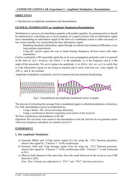
Amplitude modulation is primarily used for commercial/conventional broadcasting.<br />
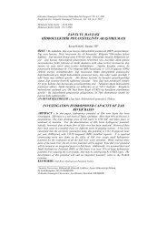
Fig.1. Unmodulated and amplitude modulated carrier example.<br />
The process of extracting the message from a modulated signal is called demodulation or detection.<br />
For AM, demodulation can be accomplished by;<br />
- Using a diode + RC circuit (envelope detection)<br />
- Using a synchronous detector (requiring exact carrier at the receiver)<br />
We have synchronous demodulators in the lab.<br />
(Question: We can easily wire carrier to the demodulator in the lab, but how do we generate carrier<br />
with exact frequency and phase at a remote receiver)<br />
EXPERIMENT<br />
1. The Amplitude Modulation<br />
a) Generate 40kHz and 1,5Vpp carrier signal (Vc) by using the “FG1”function generator,<br />
observe this signal by “Channel 1” of the oscilloscope.<br />
b) Generate 1kHz and 7Vpp message signal (Vm) by using the “FG2”function generator.<br />
observe this signal by “Channel 2” of the oscilloscope while “Channel 1” is still connected<br />
to FG1.<br />
c) Observe both channels at the same time. Save the result observed on the screen to your USB<br />
flash drive (FD).<br />
Note: Don’t change any adjustment at “FG1” and “FG2” function generators<br />
E-mail : esogucomlab@gmail.com
<strong>COMMUNICATIONS</strong> <strong>LAB</strong>. <strong>Experiment</strong> 2 : Amplitude Modulation / Demodulation<br />
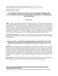
d) Make required connections to generate the AM modulated signal. Required connections are<br />
given on Fig. 2.<br />
e) Connect the “Channel 1” of the oscilloscope to the “AM” output of the AM module.<br />
f) Observe the modulated signal at the “AM” output. Save the result observed on the screen to<br />
your FD and note down your comments.<br />
g) Observe the output frequency spectrum using the “FFT” function on the oscilloscope.<br />
Hint: “FFT” analyzer can be found by pushing the “Math” button on the oscilloscope.<br />
h) Exit FFT function. Then, change the frequency and the amplitude of the carrier signal (**Do<br />
not change frequency and amplitude of the message signal ) and observe the effects of the<br />
changes. Take notes. Save display to FD at each different result.<br />
i) Then, find ideally modulated signal and over modulated signal. Save these displays and note<br />
down your comments.<br />
Hint: İdeally modulated signal index value < 1, overmodulated signal index value > 1<br />
j) Repeat h) and i) using sinusoidal message signal with 50kHz and 7Vpp.<br />
Figure 2. Module connections for AM modulation<br />
E-mail : esogucomlab@gmail.com
<strong>COMMUNICATIONS</strong> <strong>LAB</strong>. <strong>Experiment</strong> 2 : Amplitude Modulation / Demodulation<br />
2. The Amplitude Demodulation<br />
a) Generate 40kHz – 1,5Vpp carrier signal by using the “FG1”function generator.<br />
b) Generate 1kHz - 7Vpp message signal by using the “FG2”function generator.<br />
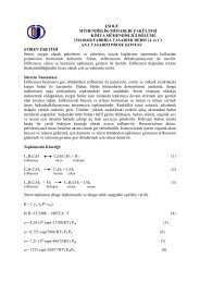
c) Make connections on the training kit to set up the AM demodulator as shown in Fig. 3.<br />
d) Connect the “Channel 1” of the oscilloscope to the “Vm” input of the AM modulator.<br />
e) Connect the “Channel 2” of the oscilloscope to the “Vo” output of the AM demodulator.<br />
f) Observe the “Vo” and “Vm” at same time. Save the result observed on the screen to your<br />
FD. Is there any difference between “Vm” and “Vo” Note down your comments for this.<br />
g) Change the frequency and the amplitude of the message signal, observe the result and take<br />
notes. Save display to FD at each different result.<br />
Figure 3. Module connections for AM demodulation<br />
E-mail : esogucomlab@gmail.com