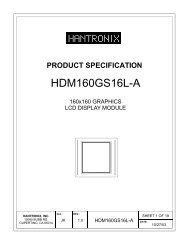
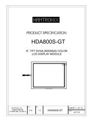
Holtek HT1622 - Hantronix, Inc
Holtek HT1622 - Hantronix, Inc
Holtek HT1622 - Hantronix, Inc

You also want an ePaper? Increase the reach of your titles
YUMPU automatically turns print PDFs into web optimized ePapers that Google loves.
<strong>HT1622</strong><br />
Pad Description<br />
Pad No. Pad Name I/O Description<br />
1 CS I<br />
2 RD I<br />
Chip selection input with Pull-high resistor. When the CS is logic<br />
high, the data and command read from or written to the <strong>HT1622</strong><br />
are disabled. The serial interface circuit is also reset. But if CS is<br />
at logic low level and is input to the CS pad, the data and command<br />
transmission between the host controller and the <strong>HT1622</strong><br />
are all enabled.<br />
READ clock input with Pull-high resistor. Data in the RAM of<br />
the <strong>HT1622</strong> are clocked out on the rising edge of the RD signal.<br />
The clocked out data will appear on the data line. The host controller<br />
can use the next falling edge to latch the clocked out data.<br />
3 WR I<br />
WRITE clock input with Pull-high resistor. Data on the DATA<br />
line are latched into the <strong>HT1622</strong> on the rising edge of the WR signal.<br />
4 DATA I/O Serial data input/output with Pull-high resistor<br />
5 VSS Negative power supply, ground<br />
6 OSCI I<br />
If the system clock comes from an external clock source, the external<br />
clock source should be connected to the OSCI pad.<br />
7 VDD Positive power supply<br />
8 VLCD I LCD operating voltage input pad<br />
9 IRQ O<br />
Time base or Watchdog Timer overflow flag, NMOS open drain<br />
output<br />
10, 11 BZ, BZ O 2kHz or 4kHz tone frequency output pair<br />
12~14 T1~T3 I Not connected<br />
15~22 COM0~COM7 O LCD common outputs<br />
23~54 SEG0~SEG31 O LCD segment outputs<br />
Absolute Maximum Ratings<br />
Supply Voltage..............................0.3V to 5.5V<br />
Input Voltage................V SS 0.3V to V DD +0.3V<br />
Storage Temperature.................50C to125C<br />
Operating Temperature ..............25C to75C<br />
Note: These are stress ratings only. Stresses exceeding the range specified under Absolute Maximum<br />
Ratings may cause substantial damage to the device. Functional operation of this device<br />
at other conditions beyond those listed in the specification is not implied and prolonged exposure<br />
to extreme conditions may affect device reliability.<br />
5 January 10, 2001