Design of Cold-Formed Steel Structural Members and Connections ...
Design of Cold-Formed Steel Structural Members and Connections ...
Design of Cold-Formed Steel Structural Members and Connections ...

You also want an ePaper? Increase the reach of your titles
YUMPU automatically turns print PDFs into web optimized ePapers that Google loves.
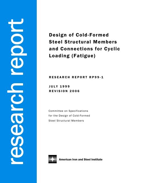
esearch report<br />
<strong>Design</strong> AISI Sponsored <strong>of</strong> <strong>Cold</strong>-<strong>Formed</strong> Research<br />
<strong>Steel</strong> Reports <strong>Structural</strong> <strong>Members</strong><br />
<strong>and</strong> <strong>Connections</strong> for Cyclic<br />
Loading (Fatigue)<br />
RESEARCH REPORT RP01-1<br />
RESEARCH REPORT RP99-1<br />
2001<br />
REVISION 2006<br />
JULY 1999<br />
REVISION 2006<br />
Committee on Specifications<br />
for the <strong>Design</strong> <strong>of</strong> <strong>Cold</strong>-<strong>Formed</strong><br />
<strong>Steel</strong> <strong>Structural</strong> <strong>Members</strong><br />
American Iron <strong>and</strong> <strong>Steel</strong> Institute
The material contained herein has been developed by researchers based on their research<br />
findings. The material has also been reviewed by the American Iron <strong>and</strong> <strong>Steel</strong> Institute<br />
Committee on Specifications for the <strong>Design</strong> <strong>of</strong> <strong>Cold</strong>-<strong>Formed</strong> <strong>Steel</strong> <strong>Structural</strong> <strong>Members</strong>. The<br />
Committee acknowledges <strong>and</strong> is grateful for the contributions <strong>of</strong> such researchers.<br />
The material herein is for general information only. The information in it should not be<br />
used without first securing competent advice with respect to its suitability for any given<br />
application. The publication <strong>of</strong> the information is not intended as a representation or warranty<br />
on the part <strong>of</strong> the American Iron <strong>and</strong> <strong>Steel</strong> Institute, or <strong>of</strong> any other person named herein, that<br />
the information is suitable for any general or particular use or <strong>of</strong> freedom from infringement <strong>of</strong><br />
any patent or patents. Anyone making use <strong>of</strong> the information assumes all liability arising from<br />
such use.<br />
Copyright 1999 American Iron <strong>and</strong> <strong>Steel</strong> Institute<br />
Revised Edition Copyright 2006 American Iron <strong>and</strong> <strong>Steel</strong> Institute
Civil Engineering Study 99-1<br />
<strong>Cold</strong>-<strong>Formed</strong> <strong>Steel</strong> Series<br />
Final Report<br />
DESIGN OF COLD-FORMED STEEL STRUCTURAL MEMBERS AND<br />
CONNECTIONS FOR CYCLIC LOADING (FATIGUE)<br />
by<br />
R. A. LaBoube <strong>and</strong> W. W. Yu<br />
A Research Project Sponsored by<br />
the American Iron <strong>and</strong> <strong>Steel</strong> Institute<br />
July, 1999<br />
Department <strong>of</strong> Civil Engineering<br />
Center for <strong>Cold</strong>-<strong>Formed</strong> <strong>Steel</strong> Structures<br />
University <strong>of</strong> Missouri-Rolla<br />
Rolla, MO
PREFACE<br />
ii<br />
Fatigue in a structural steel member or connection is the process <strong>of</strong> initiation <strong>and</strong> subsequent<br />
growth <strong>of</strong> a crack under the action <strong>of</strong> a cyclic or repetitive load. The fatigue process commonly<br />
occurs at a stress level less than the static failure condition.<br />
Although fatigue design guidelines have existed for hot-rolled steel structural members <strong>and</strong><br />
connection, there have been no generally accepted design guidelines in the AISI Specification<br />
for addressing fatigue in a cold-formed steel member or connection. Therefore, the intent <strong>of</strong> the<br />
research reported herein was to develop general design rules for design <strong>of</strong> cold-formed steel<br />
members <strong>and</strong> connections subject to fatigue loading. The fatigue design recommendations<br />
developed <strong>and</strong> reported herein are based on a review <strong>of</strong> available test data. No additional<br />
experimental studies were performed to support the suggested design recommendations.<br />
This study was made possible by the funding provided by the American Iron <strong>and</strong> <strong>Steel</strong> Institute.<br />
The AISI General Provisions Subcommittee (J. M. Fisher, Chairman) provided technical<br />
guidance for the study.
TABLE OF CONTENTS<br />
iii<br />
Page<br />
PREFACE<br />
LIST OF TABLES<br />
LIST OF FIGURES<br />
ii<br />
iv<br />
iv<br />
Introduction 1<br />
Literature Review 1<br />
Analysis <strong>of</strong> Klippstein Data 2<br />
Future Research Needs 3<br />
References 4<br />
Appendix A Proposed Specification 12<br />
Appendix B Commentary for Proposed Specification 20<br />
Appendix C <strong>Design</strong> Example 23
List <strong>of</strong> Tables<br />
iv<br />
Table<br />
Page<br />
1 Klippstein’s Fatigue <strong>Design</strong> Categories 5<br />
2 Intercept for Mean Fatigue Curves 6<br />
3 Recommended Fatigue <strong>Design</strong> Parameters for <strong>Cold</strong>-<strong>Formed</strong> <strong>Steel</strong> Structures 6<br />
4 Comparison <strong>of</strong> Recommended Fatigue <strong>Design</strong> Parameters 7<br />
A1 Fatigue <strong>Design</strong> Parameters for <strong>Cold</strong>-<strong>Formed</strong> <strong>Steel</strong> Structures 16<br />
C1 Intercept for Mean Fatigue Curves 22<br />
List <strong>of</strong> Figures<br />
Figure<br />
Page<br />
1 S-N Curves for the Various Detail Categories (Load, 1999) 8<br />
2 Typical Test Beam for Category I 9<br />
3 Typical Test Beam for Category II 10<br />
4 Typical Test Weld Attachments for Categories III <strong>and</strong> IV 11<br />
5 Typical Test Spot Weld <strong>and</strong> Screw Attachments for Category III 11<br />
A1 Typical Beam for Category I 17<br />
A2 Typical Beam for Category II 18<br />
A3 Typical Weld Attachments for Categories III <strong>and</strong> IV 19<br />
A4 Typical Spot Weld <strong>and</strong> Screw Attachments for Category III 19
Introduction<br />
1<br />
Fatigue in a structural steel member or connection is the process <strong>of</strong> initiation <strong>and</strong> subsequent<br />
growth <strong>of</strong> a crack under the action <strong>of</strong> a cyclic or repetitive load. The fatigue process commonly<br />
occurs at a stress level less than the static failure condition.<br />
When fatigue is a design consideration, its’ severity is determined primarily by three factors: (1)<br />
the number <strong>of</strong> cycles <strong>of</strong> loading, (2) the type <strong>of</strong> member <strong>and</strong> connection detail, <strong>and</strong> (3) the stress<br />
range at the detail under consideration (Fisher et al. 1998: Load 1999).<br />
Although fatigue design guidelines have existed for hot-rolled steel structural members <strong>and</strong><br />
connections there have been no generally accepted design guidelines in the AISI Specification<br />
for addressing fatigue in a cold-formed steel member or connection. Therefore, the intent <strong>of</strong> the<br />
research reported herein was to develop general design rules for design <strong>of</strong> cold-formed steel<br />
members <strong>and</strong> connections subject to fatigue loading.<br />
The fatigue design recommendations developed <strong>and</strong> reported herein are based on a review <strong>of</strong><br />
available test data. No additional experimental studies were performed to support the suggested<br />
design recommendations. In addition to design recommendations <strong>and</strong> supporting commentary, a<br />
design example for the AISI Manual is contained in Appendix C. Future research needs are also<br />
contained herein.<br />
Literature Review<br />
Based on a survey <strong>of</strong> current fatigue-design procedures <strong>and</strong> available fatigue test data, Barsom<br />
(1980) developed recommendations for future research. It was concluded that although<br />
extensive data <strong>and</strong> knowledge existed about strain-life behavior <strong>of</strong> steels, it was difficult to use<br />
this information for predicting the strain-life behavior <strong>of</strong> formed <strong>and</strong>/or fabricated components,<br />
especially welded components. Thus, Klippstein (1980, 1981, 1985, 1988) performed an<br />
extensive, multi-year research project aimed at assessing the fatigue behavior <strong>of</strong> cold-formed<br />
steel members <strong>and</strong> connections. This research focused on the application <strong>of</strong> cold-formed steel<br />
members <strong>and</strong> connections in the ground-transportation <strong>and</strong> agricultural-equipment industries.<br />
A discussion <strong>of</strong> the stress-range fatigue-design concept, including the results <strong>of</strong> 77 welded coldformed<br />
steel sheet specimens exposed to constant amplitude stress cycles were reported by<br />
Klippstein (1981). The test specimens were fabricated from steel sheet with yield strengths<br />
ranging from 30 to 80 ksi. The steel sheet conformed to ASTM grades, A715 Grade 80 (F u /F y =<br />
1.13) A607 Grade 60, <strong>and</strong> SAE 1008 (F y = 30 ksi). Several types <strong>of</strong> beam details were studied<br />
such as as-rolled surfaces, slit <strong>and</strong> sheared edges, cold-formed corners, rolled sheet steel<br />
surfaces, <strong>and</strong> drilled holes with <strong>and</strong> without screws. Welded details included flange-to-web<br />
welds, plate attachments with transverse welds, <strong>and</strong> plate attachments with short or long<br />
longitudinal welds.<br />
Klippstein, in 1985, reported on further studies <strong>of</strong> fabricated steel sheet details. Based on a<br />
compilation <strong>of</strong> 163 tests, it was reported that the results indicated that the stress-range fatigue-
design concept adopted by bridge <strong>and</strong> crane girder design specifications provided a reliable<br />
method for fatigue analysis <strong>of</strong> fabricated sheet steel details. Klippstein’s experimental studies<br />
consisted <strong>of</strong> constant amplitude fatigue tests with stress ratios <strong>of</strong> > 0 through -1.<br />
2<br />
In the 1985 report, Klippstein summarized his multi-year studies <strong>and</strong> recommended an<br />
appropriate design methodology based on mean fatigue life curves (S-N curves). A significant<br />
conclusion reported by Klippstein was that spot welded or screwed-on attachments fall under the<br />
same fatigue design category as welded attachments to a plate or a beam, transverse fillet welds,<br />
<strong>and</strong> continuous longitudinal fillet welds that are less than <strong>and</strong> equal to 2 inches in length.<br />
Klippstein (1985) also reported that intermittent welds parallel to the direction <strong>of</strong> the applied<br />
load may be considered in the same fatigue category as fillet welded attachments greater than 2<br />
inches in length parallel to the direction <strong>of</strong> the applied force.<br />
The fatigue resistance S-N curve has been expressed as an exponential relationship between<br />
stress range <strong>and</strong> life cycle (Fisher, 1970). The general relationship is <strong>of</strong>ten plotted as a linear<br />
log-log function, Eq. 1.<br />
log N = C f - m log F SR (1)<br />
C f = b - (n * s) (2)<br />
where N = number <strong>of</strong> full stress cycles<br />
m = slope <strong>of</strong> the mean fatigue analysis curve<br />
F SR = effective stress range<br />
b = intercept <strong>of</strong> the mean fatigue analysis curve<br />
n = number <strong>of</strong> st<strong>and</strong>ard deviations to obtain a desired confidence level<br />
s = approximate st<strong>and</strong>ard deviation <strong>of</strong> the fatigue data.<br />
The exponential form <strong>of</strong> Eq. 1 is as follows:<br />
F SR = (C f /N) 1/m (3)<br />
Equation 3 represents the adopted format for fatigue analysis <strong>of</strong> both the AASHTO (Fisher,1970)<br />
<strong>and</strong> AISC (Load 1999) design specifications.<br />
Using the format <strong>of</strong> Eq. 3 with m = 3, Klippstein (1988) proposed a classification system for the<br />
various stress ranges. Table 1 summarizes the categories along with the corresponding values<br />
for C f . For the computation <strong>of</strong> C f , Klippstein recommended that n <strong>and</strong> s, in Eq. 2, be taken as 2<br />
<strong>and</strong> 0.25, respectively. The intercept for the mean fatigue analysis curves, b, are summarized in<br />
Table 2.<br />
Analysis <strong>of</strong> Klippstein Data<br />
Although Klippstein (1988) recommended that bolt <strong>and</strong> screw connections <strong>and</strong> spot welds be<br />
classified as Category F, data presented by Klippstein (1985) showed that Category C provided
an appropriate classification. Therefore, the recommendation <strong>of</strong> this research is to use<br />
Category C for bolt <strong>and</strong> screw connections <strong>and</strong> spot welds.<br />
3<br />
Data (Klippstein 1985) also demonstrated that intermittent welds parallel to the direction <strong>of</strong> the<br />
applied force may be classified in Category D. Thus, this research recommends that Category D<br />
be used for intermittent welds parallel to the direction <strong>of</strong> the applied force.<br />
The proposed fatigue categories are summarized in Table 3. To avoid confusion with fatigue<br />
categories contained in other design specifications the categories in Table 3 use Roman<br />
Numerals.<br />
Fluctuation in stress below a defined threshold will not cause a fatigue crack. However,<br />
Klippstein’s research was focused on the application <strong>of</strong> cold-formed steel members <strong>and</strong><br />
connections in the ground-transportation <strong>and</strong> agricultural-equipment industries. These<br />
applications experience constant amplitude stress range, <strong>and</strong> therefore are not exposed to a<br />
threshold stress. Therefore, Klippstein made no attempt to define a threshold stress. To provide<br />
a threshold stress for design, F TH was computed using Klippstein’s mean fatigue life curves <strong>and</strong><br />
the number <strong>of</strong> cycles that define the threshold stress in the AISC Specification (1999). Figure 1<br />
summarizes the AISC mean fatigue life curves <strong>and</strong> corresponding number <strong>of</strong> cycles, N, at the<br />
threshold stress. The computed threshold stress for each category is listed in Table 3.<br />
Table 3 presents a summary <strong>of</strong> the recommended fatigue categories <strong>and</strong> the corresponding<br />
design parameters. Also presented in Table 3 are the AISC design parameters for each category.<br />
In all cases, good correlation is shown between the recommended design parameters <strong>and</strong> AISC’s<br />
design parameters.<br />
Using Eq. 3, with m = 3 <strong>and</strong> N = 1,000,000, values <strong>of</strong> F SR were determined using both the AISI<br />
<strong>and</strong> AISC design parameters (Table 3). Summarized in Table 4 are the resulting F SR values, as<br />
well as the ratio <strong>of</strong> AISI to AISC F SR values. For the four proposed fatigue categories, the ratio<br />
<strong>of</strong> AISI to AISC F SR values ranged from 0.896 to 1.085. Variation in the number <strong>of</strong> cycles, N,<br />
will not alter the resulting ratios. These ratios demonstrate the good correlation between the<br />
proposed AISI design formulation <strong>and</strong> the AISC design method.<br />
Appendix A contains a draft design specification for cold-formed steel structural members <strong>and</strong><br />
connections for cyclic loading (fatigue). Appendix B contains a draft commentary to support the<br />
draft specification.<br />
Future Research Needs<br />
Although the proposed design recommendations are based on an extensive collection <strong>of</strong> data,<br />
future research is recommended to broaden the applicability <strong>of</strong> the fatigue design for coldformed<br />
steel members <strong>and</strong> connections. Particular emphasis should be placed on future research<br />
to study additional fabrication details, effect <strong>of</strong> holes, <strong>and</strong> a broader array <strong>of</strong> screw sizes.<br />
References
Barsom, J. M., Klippstein, K. H., <strong>and</strong> Shoemaker, A. K. (1980), “Fatigue Behavior <strong>of</strong> Sheet<br />
<strong>Steel</strong>s for Automotive Applications,” Research Report SG 80-2, American Iron <strong>and</strong> <strong>Steel</strong><br />
Institute<br />
4<br />
Klippstein, K. H. (1980), “Fatigue Behavior <strong>of</strong> Sheet <strong>Steel</strong> Fabrication Details,” Proceedings <strong>of</strong><br />
the Fifth International Specialty Conference on <strong>Cold</strong>-<strong>Formed</strong> <strong>Steel</strong> Structures, University <strong>of</strong><br />
Missouri-Rolla<br />
Klippstein, K. H. (1981), “Fatigue Behavior <strong>of</strong> <strong>Steel</strong>-Sheet Fabrication Details,” SAE Technical<br />
Paper Series 810436, International Congress <strong>and</strong> Exposition, Detroit, MI<br />
Klippstein, K. H. (1985), “Fatigue <strong>of</strong> Fabricated <strong>Steel</strong>-Sheet Details - Phase II,” SAE Technical<br />
Paper Series 850366, International Congress <strong>and</strong> Exposition, Detroit, MI<br />
Klippstein, K. H. (1988), “Fatigue <strong>Design</strong> Curves for <strong>Structural</strong> Fabrication Details Made <strong>of</strong><br />
Sheet <strong>and</strong> Plate <strong>Steel</strong>,” unpublished AISI research report.<br />
Fisher, J. W., Kulak, G. L., <strong>and</strong> Smith, I. F.C. (1998), “A Fatigue Primer for <strong>Structural</strong><br />
Engineers,” National <strong>Steel</strong> Bridge Alliance.<br />
Fisher, J. W. , Frank, K. H., Hirt, M. A., <strong>and</strong> McNamee, B. M. (1970), “Effect <strong>of</strong> Weldments on<br />
the Fatigue Strength <strong>of</strong> Beams,” National Cooperative Highway Research Program, Report 102,<br />
Washington, D.C.<br />
Load <strong>and</strong> Resistance Factor <strong>Design</strong> Specification for <strong>Structural</strong> <strong>Steel</strong> Buildings (1999),<br />
American Institute <strong>of</strong> <strong>Steel</strong> Construction, Chicago, IL
Table 1<br />
Klippstein’s Fatigue <strong>Design</strong> Categories<br />
5<br />
Description Stress Constant<br />
Category C f<br />
Base metal <strong>and</strong> components with A 3.16x10 10<br />
as received surfaces, including<br />
sheared edges <strong>and</strong> cold-formed<br />
corners.<br />
Base metal <strong>and</strong> weld metal in B 1.0x10 10<br />
members connected by continuous<br />
longitudinal fillet welds.<br />
Continuously welded attachments to C 3.16x10 9<br />
a plate or a beam, transverse web<br />
stiffeners, transverse fillet welds,<br />
weld washers with outside diameter<br />
less than 2 inches, <strong>and</strong> continuous<br />
longitudinal welds in regions <strong>of</strong><br />
cold-forming <strong>and</strong> subsequent welding.<br />
Weld washers with diameter ranging D 1.0x10 9<br />
from 2 to 4 inches. Any welded<br />
attachment with a length <strong>of</strong> 2 to 4<br />
inches parallel to the direction <strong>of</strong> the<br />
applied stress. Transverse welds in<br />
regions <strong>of</strong> cold-forming.<br />
Attachments longer than 4 inches E 3.16x10 8<br />
parallel to the direction <strong>of</strong> the applied<br />
stress, <strong>and</strong> intermittent welds parallel<br />
to the direction <strong>of</strong> the applied stress.<br />
Bolt <strong>and</strong> screw holes in connections F 1.0x10 10<br />
<strong>and</strong> other punched <strong>and</strong> drilled holes,<br />
spot welds, <strong>and</strong> shear connectors.
6<br />
Table 2<br />
Intercept for Mean Fatigue Curves<br />
Stress Category<br />
b<br />
A 11.0<br />
B 10.5<br />
C 10.0<br />
D 9.5<br />
E 9.0<br />
F 10.5<br />
Table 3<br />
Recommended Fatigue <strong>Design</strong> Parameters for <strong>Cold</strong>-<strong>Formed</strong> <strong>Steel</strong> Structures<br />
Description Stress Constant Threshold Illustrative<br />
Category C f F TH Example<br />
(ksi)<br />
As received base metal <strong>and</strong> I 3.2x10 10 25 Fig. 2<br />
components with as rolled surfaces, (2.5x10 10 ) (24)<br />
including sheared edges <strong>and</strong><br />
cold-formed corners.<br />
As received base metal <strong>and</strong> weld II 1.0x10 10 15 Fig. 3<br />
metal in members connected by (1.2x10 10 ) (16)<br />
continuous longitudinal welds.<br />
Welded attachments to a plate III 3.2x10 9 16 Fig. 4, 5<br />
or a beam, transverse fillet welds, (4.4x10 9 ) (10)<br />
<strong>and</strong> continuous longitudinal fillet<br />
welds less than <strong>and</strong> equal to 2 inches.<br />
Bolt <strong>and</strong> screw connections<br />
<strong>and</strong> spot welds.<br />
Longitudinal fillet welded IV 1.0x10 9 9 Fig. 4<br />
attachments greater than 2 inches (1.0x10 9 ) (7)<br />
parallel to the direction <strong>of</strong> the<br />
applied stress, <strong>and</strong> intermittent<br />
welds parallel to the direction <strong>of</strong> the<br />
applied force.<br />
The numbers in ( ) are the corresponding AISC values for information only.
Table 4<br />
Comparison <strong>of</strong> Recommended Fatigue <strong>Design</strong> Parameters<br />
7<br />
Category C f C f F SR F SR (F SR ) AISI / (F SR ) AISC<br />
AISI AISC AISI AISC<br />
(ksi) (ksi)<br />
I 3.2 x 10 10 2.5 x 10 10 3.17 2.92 1.085<br />
II 1.0 x 10 10 1.2 x 10 10 2.15 2.29 0.939<br />
III 3.2 x 10 9 4.4 x 10 9 1.47 1.64 0.896<br />
IV 1.0 x 10 9 1.1 x 10 9 1.00 1.03 0.971<br />
F SR calculations used Eq. 3 with m = 3 <strong>and</strong> N = 1,000,000 cycles.
8<br />
100<br />
500<br />
ST-STRESS RANGE (ksi)<br />
10<br />
A<br />
B<br />
B'<br />
C D<br />
E<br />
100<br />
ST-STRESS RANGE (MPa)<br />
E'<br />
10<br />
10 5 10 6 10 7 10 8<br />
N-NUMBER OF CYCLES<br />
Figure 1 S-N Curves for the Various Detail Categories (Load 1999)
Figure 2 Typical Test Beam for Category I<br />
9
Figure 3 Typical Test Beam for Category II<br />
10
11<br />
Figure 4 Typical Test Weld Attachments for Categories III <strong>and</strong> IV<br />
Figure 5 Typical Test Spot Weld <strong>and</strong> Screw Attachments for Category III
12<br />
Appendix A<br />
Proposed Specification
DESIGN OF COLD-FORMED STEEL STRUCTURAL MEMBERS AND<br />
CONNECTIONS FOR CYCLIC LOADING (FATIGUE)<br />
13<br />
This design procedure shall apply to cold-formed steel members <strong>and</strong> connections subject to<br />
cyclic loading within the elastic range <strong>of</strong> stresses <strong>of</strong> frequency <strong>and</strong> magnitude sufficient to<br />
initiate cracking <strong>and</strong> progressive failure (fatigue).<br />
1. General<br />
The provisions <strong>of</strong> this section apply to stresses calculated on the basis <strong>of</strong> unfactored loads. The<br />
maximum permitted tensile stress due to unfactored loads is 0.6 F y .<br />
Stress range is defined as the magnitude <strong>of</strong> the change in stress due to the application or removal<br />
<strong>of</strong> the unfactored live load. In the case <strong>of</strong> a stress reversal, the stress range shall be computed as<br />
the numerical sum <strong>of</strong> maximum repeated tensile <strong>and</strong> compressive stresses or the numerical sum<br />
<strong>of</strong> maximum shearing stresses <strong>of</strong> opposite direction at the point <strong>of</strong> probable crack initiation.<br />
Evaluation <strong>of</strong> fatigue resistance is not required if the live load stress range is less than the<br />
threshold stress range, F TH , given in Table A1.<br />
Evaluation <strong>of</strong> fatigue resistance is not required if the number <strong>of</strong> cycles <strong>of</strong> application <strong>of</strong> live load<br />
is less than 20,000.<br />
The cyclic load resistance determined by the provisions <strong>of</strong> this section are applicable to<br />
structures with suitable corrosion protection or subject only to non-agressive atmospheres.<br />
The cyclic load resistance determined by the provisions <strong>of</strong> this section is applicable only to<br />
structures subject to temperatures not exceeding 300°F.<br />
The contract documents shall provide, either complete details including weld sizes, or shall<br />
specify the planned cycle life <strong>and</strong> the maximum range <strong>of</strong> moments, shears, <strong>and</strong> reactions for the<br />
connections.<br />
2. Calculation <strong>of</strong> Maximum Stresses <strong>and</strong> Stress Ranges<br />
Calculated stresses shall be based upon elastic analysis. Stresses shall not be amplified by stress<br />
concentration factors for geometrical discontinuities.<br />
For bolts <strong>and</strong> threaded rods subject to axial tension, the calculated stresses shall include the<br />
effects <strong>of</strong> prying action, if applicable.<br />
In the case <strong>of</strong> axial stress combined with bending, the maximum stresses, <strong>of</strong> each kind, shall be<br />
those determined for concurrent arrangements <strong>of</strong> applied load.<br />
For members having symmetric cross sections, the fasteners <strong>and</strong> welds shall be arranged<br />
symmetrically about the axis <strong>of</strong> the member, or the total stresses including those due to
eccentricity shall be included in the calculation <strong>of</strong> the stress range.<br />
14<br />
For axially stressed angle members where the center <strong>of</strong> gravity <strong>of</strong> the connecting welds lies<br />
between the line <strong>of</strong> the center <strong>of</strong> gravity <strong>of</strong> the angle cross section <strong>and</strong> the center <strong>of</strong> the<br />
connected leg, the effects <strong>of</strong> eccentricity shall be ignored. If the center <strong>of</strong> gravity <strong>of</strong> the<br />
connecting welds lies outside this zone, the total stresses, including those due to joint<br />
eccentricity, shall be included in the calculation <strong>of</strong> stress range.<br />
3. <strong>Design</strong> Stress Range<br />
If the stress range is less than the fatigue threshold stress range, F TH , fatigue is not a limit state.<br />
Otherwise, the range <strong>of</strong> stress at service loads shall not exceed the design stress range computed<br />
using Equation A1, but F SR shall not be less than the fatigue threshold, F TH .<br />
For all stress categories,<br />
F SR = (C f /N) 0.333<br />
(A1)<br />
where:<br />
F SR = <strong>Design</strong> stress range<br />
C f = Constant from Table A1<br />
N = Number <strong>of</strong> stress range fluctuations in design life,<br />
= Number <strong>of</strong> stress range fluctuations per day x 365 x years <strong>of</strong> design life.<br />
F TH = Threshold fatigue stress range, maximum stress range for indefinite design life<br />
from Table A1<br />
4. Bolts <strong>and</strong> Threaded Parts<br />
For mechanically fastened connections loaded in shear, the maximum range <strong>of</strong> stress in the<br />
connected material at service loads shall not exceed the design stress range computed using<br />
Equation A1. The factor C f shall be taken as 22x10 8 . The threshold stress, F TH , shall be taken as<br />
7 ksi.<br />
For not-fully-tightened high-strength bolts, common bolts, <strong>and</strong> threaded anchor rods with cut,<br />
ground or rolled threads, the maximum range <strong>of</strong> tensile stress on the net tensile area from applied<br />
axial load <strong>and</strong> moment plus load due to prying action shall not exceed the design stress range<br />
computed using Equation A1. The factor C f shall be taken as 3.9x10 8 . The threshold stress, F TH ,<br />
shall be taken as 7 ksi. The net tensile area is given by Equation A2.<br />
A t = (π/4) [d b - (0.9743/n)] 2<br />
(A2)<br />
where:<br />
d b = nominal diameter (body or shank diameter)<br />
n = number <strong>of</strong> threads per inch
5. Special Fabrication Requirements<br />
15<br />
Backing bars that are parallel to the stress field are permitted to remain in place, <strong>and</strong> if used,<br />
shall be continuous.<br />
In transverse joints subject to tension, backing bars, if used, shall be removed <strong>and</strong> the joint back<br />
gouged <strong>and</strong> welded.<br />
Flame cut edges subject to cyclic stress ranges shall have a surface smoothness not more than<br />
ANSI 1000.<br />
Re-entrant corners at cuts, copes <strong>and</strong> weld access holes shall form a radius <strong>of</strong> not less than 3/8<br />
in., by pre-drilling or sub-punching <strong>and</strong> reaming a hole, or by thermal cutting to form the radius<br />
<strong>of</strong> the cut. If the radius portion is formed by thermal cutting, the cut surface shall be ground to a<br />
bright metal contour to provide a radiused transition, free <strong>of</strong> notches, with a surface smoothness<br />
not more that ANSI 1000.<br />
For transverse butt joints in regions <strong>of</strong> high tensile stress, weld tabs shall be used to provide for<br />
cascading the weld termination outside the finished joint. End dams shall not be used. Weld<br />
tabs shall be removed <strong>and</strong> the end <strong>of</strong> the weld finished flush with the edge <strong>of</strong> the member.
Table A1<br />
Fatigue <strong>Design</strong> Parameters for <strong>Cold</strong>-<strong>Formed</strong> <strong>Steel</strong> Structures<br />
16<br />
Description Stress Constant Threshold Illustrative<br />
Category C f F TH Example<br />
(ksi)<br />
As received base metal <strong>and</strong> I 3.2x10 10 25 A1<br />
components with as rolled surfaces,<br />
including sheared edges <strong>and</strong><br />
cold-formed corners.<br />
As received base metal <strong>and</strong> weld II 1.0x10 10 15 A2<br />
metal in members connected by<br />
continuous longitudinal welds.<br />
Welded attachments to a plate III 3.2x10 9 16 A3, A4<br />
or a beam, transverse fillet welds,<br />
<strong>and</strong> continuous longitudinal fillet<br />
welds less than <strong>and</strong> equal to 2 inches.<br />
Bolt <strong>and</strong> screw connections<br />
<strong>and</strong> spot welds.<br />
Longitudinal fillet welded IV 1.0x10 9 9 A4<br />
attachments greater than 2 inches<br />
parallel to the direction <strong>of</strong> the<br />
applied stress, <strong>and</strong> intermittent<br />
welds parallel to the direction <strong>of</strong> the<br />
applied force.
17<br />
SHEAR EDGES<br />
COLD-FORMED CORNER<br />
COLD-FORMED STEEL CHANNELS<br />
CATEGORY I<br />
Figure A1 Typical Test Beam for Category I
18<br />
WELD<br />
WELDED I BEAM<br />
CATEGORY II<br />
Figure A2 Typical Test Beam for Category II
19<br />
TYPICAL PLATE<br />
L<br />
L<br />
(a) TRANSVERSE WELDS<br />
CATEGORY III<br />
(b) LONGITUDINAL WELDS<br />
FOR CATEGORY III L ≤ 2"<br />
FOR CATEGORY IV 2" < L ≤4"<br />
Figure A3 Typical Test Weld Attachments for Categories III <strong>and</strong> IV<br />
(c) SPOT WELDS<br />
(d) SCREWS<br />
Figure A4 Typical Test Spot Weld <strong>and</strong> Screw Attachments for Category III
20<br />
Appendix B<br />
Commentary for Proposed Specification
COMMENTARY ON<br />
DESIGN OF COLD-FORMED STEEL STRUCTURAL MEMBERS AND<br />
CONNECTIONS FOR CYCLIC LOADING (FATIGUE)<br />
21<br />
Fatigue in a cold-formed steel member or connection is the process <strong>of</strong> initiation <strong>and</strong> subsequent<br />
growth <strong>of</strong> a crack under the action <strong>of</strong> a cyclic or repetitive load. The fatigue process commonly<br />
occurs at a stress level less than the static failure condition.<br />
When fatigue is a design consideration, its severity is determined primarily by three factors: (1)<br />
the number <strong>of</strong> cycles <strong>of</strong> loading, (2) the type <strong>of</strong> member <strong>and</strong> connection detail, <strong>and</strong> (3) the stress<br />
range at the detail under consideration (Fisher et al. 1998).<br />
Fluctuation in stress which does not involve tensile stress does not cause crack propagation <strong>and</strong><br />
is not considered to be a fatigue situation.<br />
When fabrication details involving more than one category occur at the same location in a<br />
member, the design stress range at the location must be limited to that <strong>of</strong> the most restrictive<br />
category. By locating notch-producing fabrication details in regions subject to a small range <strong>of</strong><br />
stress, the need for a member larger than required by static loading will <strong>of</strong>ten be eliminated.<br />
Research by Barsom (1980) <strong>and</strong> Klippstein (1988, 1985, 1981, 1980) developed fatigue<br />
information on the behavior <strong>of</strong> sheet <strong>and</strong> plate steel weldments <strong>and</strong> mechanical connections.<br />
Using regression analysis, mean fatigue life curves (S-N curves) with the corresponding st<strong>and</strong>ard<br />
deviation were developed. The fatigue resistance S-N curve has been expressed as an<br />
exponential relationship between stress range <strong>and</strong> life cycle (Fisher, 1970). The general<br />
relationship is <strong>of</strong>ten plotted as a linear log-log function, Eq. C1.<br />
log N = C f - m log F SR<br />
C f = b - (n * s)<br />
(C1)<br />
(C2)<br />
where N = number <strong>of</strong> full stress cycles<br />
m = slope <strong>of</strong> the mean fatigue analysis curve<br />
F SR = effective stress range<br />
b = intercept <strong>of</strong> the mean fatigue analysis curve from Table C1<br />
n = number <strong>of</strong> st<strong>and</strong>ard deviations to obtain a desired confidence level<br />
= 2 for C f given in the Specification<br />
s = approximate st<strong>and</strong>ard deviation <strong>of</strong> the fatigue data<br />
= 0.25 (Klippstein, 1988)<br />
The data base for these design provisions are based upon cyclic testing <strong>of</strong> real joints; therefore,<br />
stress concentrations have been accounted for by the category in Table A1 <strong>of</strong> the Specification.<br />
It is not intended that the allowable stress ranges should be compared to “hot-spot” stresses<br />
determined by finite element analysis. Also, calculated stresses computed by ordinary analysis
22<br />
need not be amplified by stress concentration factors at geometrical discontinuities <strong>and</strong><br />
changes <strong>of</strong> cross section. All categories were found to have a common slope with m = -3.<br />
Equation 1 <strong>of</strong> the Specification is to be used to calculate the design stress range for the chosen<br />
design life, N. Table A1 <strong>of</strong> the Specification provides a classification system for the various<br />
stress categories. This also provides the constant C f that is applicable to the stress category that<br />
is required for calculating the design stress range F SR .<br />
Table C1<br />
Intercept for Mean Fatigue Curves<br />
Stress Category<br />
b<br />
I 11.0<br />
II 10.5<br />
III 10.0<br />
IV 9.5<br />
The provisions for bolts <strong>and</strong> threaded parts were taken from the AISC Specification (Load 1999).<br />
References<br />
Barsom, J. M., Klippstein, K. H., <strong>and</strong> Shoemaker, A. K. (1980), “Fatigue Behavior <strong>of</strong> Sheet<br />
<strong>Steel</strong>s for Automotive Applications,” Research Report SG 80-2, American Iron <strong>and</strong> <strong>Steel</strong><br />
Institute.<br />
Fisher, J. W., Kulak, G. L., <strong>and</strong> Smith, I. F.C. (1998), “A Fatigue Primer for <strong>Structural</strong><br />
Engineers,” National <strong>Steel</strong> Bridge Alliance.<br />
Klippstein, K. H. (1980), “Fatigue Behavior <strong>of</strong> Sheet <strong>Steel</strong> Fabrication Details,” Proceedings <strong>of</strong><br />
the Fifth International Specialty Conference on <strong>Cold</strong>-<strong>Formed</strong> <strong>Steel</strong> Structures, University <strong>of</strong><br />
Missouri-Rolla<br />
Klippstein, K. H. (1981), “Fatigue Behavior <strong>of</strong> <strong>Steel</strong>-Sheet Fabrication Details,” SAE Technical<br />
Paper Series 810436, International Congress <strong>and</strong> Exposition, Detroit, MI.<br />
Klippstein, K. H. (1985), “Fatigue <strong>of</strong> Fabricated <strong>Steel</strong>-Sheet Details - Phase II,” SAE Technical<br />
Paper Series 850366, International Congress <strong>and</strong> Exposition, Detroit, MI.<br />
Klippstein, K. H. (1988), “Fatigue <strong>Design</strong> Curves for <strong>Structural</strong> Fabrication Details Made <strong>of</strong><br />
Sheet <strong>and</strong> Plate <strong>Steel</strong>,” unpublished AISI research report.<br />
LaBoube, R. A., <strong>and</strong> Yu, W. W. (1999), “<strong>Design</strong> <strong>of</strong> <strong>Cold</strong>-<strong>Formed</strong> <strong>Steel</strong> <strong>Structural</strong> <strong>Members</strong> <strong>and</strong><br />
<strong>Connections</strong> for Cyclic Loading (Fatigue),” Final Report, Civil Engineering Study 99-1, <strong>Cold</strong>-<br />
<strong>Formed</strong> <strong>Steel</strong> Series, Department <strong>of</strong> Civil Engineering, University <strong>of</strong> Missouri-Rolla.
23<br />
Appendix C<br />
<strong>Design</strong> Example
Given:<br />
24<br />
(1) <strong>Cold</strong>-formed steel flexural member with sheeting attached to its compression flange.<br />
(2) The flexural member is C-shaped in geometry, 9CS3x075<br />
(3) ASTM A653 Grade 50 steel was used to roll the C-shape.<br />
(4) Sheeting is attached using self-drilling screws which are spaced 12 in. center-to-center.<br />
(5) A 20 year life expectancy is stipulated for the design.<br />
If the C-shape is subjected to a loading rate <strong>of</strong> 2 cycles per hour, determine the design stress<br />
range for the C-shape.<br />
Solution:<br />
The number <strong>of</strong> cycles is,<br />
N = 2 cycles/hour x 24 hrs/day x 365 days/year x 20 year life = 350,400 cycles<br />
(A) Between the fasteners:<br />
The C-shape has rolled corners, therefore stress category I applies, C f = 3.2x10 10 <strong>and</strong> F TH = 25<br />
ksi.<br />
The maximum stress range is 0.6 x 50 ksi = 30 ksi. Because F TH is less that 30 ksi, fatigue must<br />
be considered.<br />
The fatigue design stress range for the C-shaped member is,<br />
F SR = (C f /N) 0.333<br />
= ( 3.2x10 10 / 350,400) 0.333<br />
= 44.86 ksi<br />
Because F SR is greater than 30 ksi, fatigue will not control the design <strong>of</strong> the C-shaped flexural<br />
member between the fastener locations.<br />
(B) At the location <strong>of</strong> the attachment:<br />
The attachment <strong>of</strong> the sheet to the C-shape uses self-drilling screws, thus the design <strong>of</strong> the C-<br />
shape is governed by stress category III, C f = 3.2x10 9 <strong>and</strong> F TH = 16 ksi.<br />
Because F TH is less than 30 ksi, fatigue must be considered.<br />
The fatigue design stress range for the attachment is,
F SR = (C f /N) 0.333<br />
25<br />
= ( 3.2x10 9 / 350,400) 0.333<br />
= 20.84 ksi<br />
Because F SR is less than 30 ksi, fatigue will control the design <strong>of</strong> the C-shape at the sheeting<br />
attachment locations.
American Iron <strong>and</strong> <strong>Steel</strong> Institute<br />
1140 Connecticut Avenue, NW<br />
Suite 705<br />
Washington, DC 20036<br />
www.steel.org<br />
Research Report RP-99-1