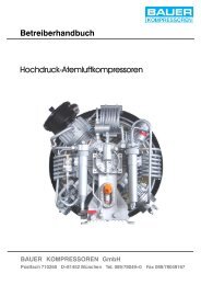
Operator's Manual High Pressure Breathing Air Compressors
Operator's Manual High Pressure Breathing Air Compressors
Operator's Manual High Pressure Breathing Air Compressors
Create successful ePaper yourself
Turn your PDF publications into a flip-book with our unique Google optimized e-Paper software.
10. FILTER SYSTEM P41 AND P61<br />
10.1. APPLICATION AND SUMMARY DESCRIPTION<br />
Filter systems P41 or P61 (Fig. 28) consist of:<br />
• Separator with final pressure safety valve<br />
• Non--return valve between separator and purifier<br />
• <strong>High</strong> pressure purifier<br />
• SECURUS indicator unita) • Venting valve with pressure gauge<br />
• <strong>Pressure</strong> maintaining/non--return valve<br />
42<br />
Operator’s <strong>Manual</strong><br />
The system is integrated into the compressor unit, i.e. the filters and other components are mounted on the frame, the pressure<br />
gauges are situated at the filling panel. If the SECURUS monitoring system is provided, the breathing air regeneration process and<br />
the degree of dryness of the air are continuously monitored during the regeneration process by measuring the cartridge saturation<br />
within the filter cartridge.<br />
2<br />
1<br />
3<br />
Fig. 28 Filter system P41 left, P61 right with SECURUS--monitoring unit<br />
1 Oil and water separator<br />
2 Final pressure safety valve<br />
3 Non -return valve<br />
4 Purifier<br />
a) optional extra<br />
6<br />
4<br />
7<br />
5<br />
1<br />
3<br />
5 SECURUS indicator unit a)<br />
6 Bleeding valve with pressure gauge<br />
7 <strong>Pressure</strong> maintaining/non -return valve<br />
6<br />
4<br />
5<br />
7


