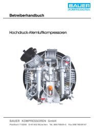
Operator's Manual High Pressure Breathing Air Compressors
Operator's Manual High Pressure Breathing Air Compressors
Operator's Manual High Pressure Breathing Air Compressors

Create successful ePaper yourself
Turn your PDF publications into a flip-book with our unique Google optimized e-Paper software.
9. FILTER SYSTEM P21<br />
9.1. DESCRIPTION<br />
38<br />
Operator’s <strong>Manual</strong><br />
The air leaving the final stage is cooled in the after--cooler to approx. 10 -- 15 °C (18 -- 27 °F) above ambient temperature and then<br />
enters filter system P21 with TRIPLEX longlife cartridge (Fig. 26).<br />
The filter assembly consists of separator and cartridge chamber. In the separator surrounding the cartridge chamber liquid oil and<br />
water particles are reliably separated from the compressed medium by a pipe nozzle.<br />
Residual oil and water vapors are then removed by the TRIPLEX longlife cartridge. The quality ofthe breathing air produced conforms<br />
to DIN EN 12021.<br />
4<br />
3<br />
2<br />
1<br />
Fig. 26 Filter system P21<br />
9.2. CONDENSATE DRAINAGE<br />
5<br />
6<br />
7<br />
8<br />
9<br />
10<br />
11<br />
1 Filter inlet<br />
2 Jet pipe<br />
3 Filter head<br />
4 Final pressure safety valve<br />
5 Housing<br />
6 Chamber separator<br />
7 Cartridge<br />
8 Filter outlet<br />
9 <strong>Pressure</strong> maintaining valve<br />
10 Condensate drain tap<br />
11 Condensate outlet<br />
Drain condensate from separator and cartridge chamber regularly by slowly opening drain taps (10, Fig. 26)<br />
-- before changing cartridge<br />
-- before each filling procedure<br />
-- during filling procedure every 15 minutes.<br />
Slowly open left tap first, then right tap approx. 1/3 turn to the left, until condensate is completely drained. The taps close by spring<br />
pressure, if necessary tighten by hand to make sure they are completely air--tight.