Operator's Manual High Pressure Breathing Air Compressors
Operator's Manual High Pressure Breathing Air Compressors
Operator's Manual High Pressure Breathing Air Compressors

Create successful ePaper yourself
Turn your PDF publications into a flip-book with our unique Google optimized e-Paper software.
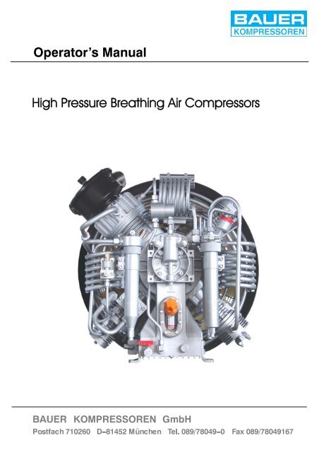
Operator’s <strong>Manual</strong><br />
<strong>High</strong> <strong>Pressure</strong> <strong>Breathing</strong> <strong>Air</strong> <strong>Compressors</strong>
Operator’s <strong>Manual</strong><br />
INTRODUCTION<br />
This manual contains general information and instructions to operate<br />
and maintain high pressure breathing air compressor units.<br />
Before taking the compressor into operation it is essential to study the<br />
instruction manual of that compressor.<br />
All instructions should be observed and carried out in the order laid<br />
down to prevent damage and premature wear to the equipment and<br />
the units served by it.<br />
While every effort is made to ensure the accuracy of the particulars<br />
contained in this manual, the manufacturing company will not, under<br />
any circumstances, be held liable for any inaccuracies or the consequences<br />
thereof.<br />
WARNING<br />
The breathing air produced with this high pressure compressor is subject<br />
to strict quality standards.Ignoring the operating and maintenance<br />
instructions can lead to severe injury or in serious cases even death.<br />
We reserve the right to make changes to the technology of our compressors<br />
as well as to this accompanying documentation in accordance<br />
to technical progress.<br />
Edition January 2005<br />
© 2005 BAUER Kompressoren GmbH, Munich<br />
All rights reserved.<br />
i
TABLE OF CONTENTS<br />
ii<br />
Operator’s <strong>Manual</strong><br />
1. GENERAL ................................................................................... 1<br />
1.1. PURPOSE AND SHORT DESCRIPTION ......................................................... 1<br />
1.2. THEORETICAL PRINCIPLES ................................................................... 2<br />
1.3. DESIGN AND MODE OF OPERATION ........................................................... 4<br />
2. SAFETY REGULATIONS ...................................................................... 8<br />
2.1. GENERAL ................................................................................... 8<br />
2.2. NOTES AND WARNING SIGNS ................................................................. 9<br />
2.3. IDENTIFYING THE SAFETY NOTICES ........................................................... 9<br />
2.4. FUNDAMENTAL SAFETY NOTICES ............................................................. 9<br />
2.5. SAFETY REGULATIONS (EC; partly Germany, only) ................................................ 12<br />
3. INSTALLATION, OPERATION .................................................................. 13<br />
3.1. INSTALLATION OF THE COMPRESSOR UNIT .................................................... 13<br />
3.2. COMPRESSOR ROOM CONDITIONS: ........................................................... 14<br />
3.3. NATURAL VENTILATION ....................................................................... 16<br />
3.4. ARTIFICIAL VENTILATION ..................................................................... 19<br />
3.5. ELECTRICAL INSTALLATION ................................................................... 22<br />
3.6. TAKING INTO OPERATION ..................................................................... 23<br />
3.7. FILLING PROCEDURE ........................................................................ 25<br />
3.8. SHUT -DOWN PROCEDURE ................................................................... 28<br />
4. MAINTENANCE .............................................................................. 29<br />
4.1. MAINTENANCE RECORD ...................................................................... 29<br />
4.2. MAINTENANCE INTERVALS ................................................................... 29<br />
5. MAINTENANCE SCHEDULE ................................................................... 30<br />
5.1. MAINTENANCE INTERVALS ................................................................... 30<br />
5.2. MAINTENANCE RECORD ...................................................................... 31<br />
6. STORAGE, PRESERVATION ................................................................... 32<br />
6.1. GENERAL ................................................................................... 32<br />
6.2. PREPARATION ............................................................................... 32<br />
6.3. PRESERVING THE COMPRESSOR ............................................................. 32<br />
6.4. PRESERVING THE MOTOR/ENGINE ............................................................ 32<br />
6.5. PREVENTIVE MAINTENANCE DURING STORAGE ............................................... 32<br />
6.6. REACTIVATING THE COMPRESSOR UNIT ...................................................... 33<br />
7. REPAIR INSTRUCTIONS ...................................................................... 34<br />
7.1. GENERAL ................................................................................... 34<br />
8. TROUBLE -SHOOTING ........................................................................ 35<br />
9. FILTER SYSTEM P21 .......................................................................... 37<br />
9.1. DESCRIPTION ............................................................................... 37<br />
9.2. CARTRIDGE SAFETY BORE ................................................................... 38<br />
9.3. LIFETIME .................................................................................... 38<br />
9.4. GENERAL INSTRUCTIONS FOR FILTER MAINTENANCE .......................................... 39<br />
9.5. CONDENSATE DRAINAGE .....................................................................<br />
39
Operator’s <strong>Manual</strong><br />
9.6. FILTER CARTRIDGES ......................................................................... 39<br />
9.7. FILTER SERVICE LIFETIME .................................................................... 39<br />
9.8. CARTRIDGE CHANGE ........................................................................<br />
40<br />
iii
TABLE OF CONTENTS<br />
iv<br />
Operator’s <strong>Manual</strong><br />
9.9. FILLING VALVE MAINTENANCE ................................................................ 40<br />
9.10. REPLACEMENT INTERVALS ................................................................... 41<br />
9.11. CONDENSATE DRAINAGE ..................................................................... 41<br />
9.12. CARTRIDGE CHANGE ........................................................................ 41<br />
10. FILTER SYSTEM P41 AND P61 ................................................................. 42<br />
10.1. APPLICATION AND SUMMARY DESCRIPTION ................................................... 42<br />
10.2. FUNCTION ................................................................................... 43<br />
10.3. FILTER MAINTENANCE ....................................................................... 48<br />
10.4. TECHNICAL DATA ............................................................................ 51<br />
11. LUBRICATING OIL LIST ....................................................................... 52<br />
11.1. GENERAL ................................................................................... 52<br />
11.2. TYPE OF OIL ................................................................................. 53<br />
11.3. OIL CHANGE ................................................................................. 53<br />
12. TRANSPORTING COMPRESSED AIR CYLINDERS ............................................... 54<br />
13. FURTHER FILLING POSSIBILITIES ............................................................. 55<br />
13.1. OVERFLOW .................................................................................. 55<br />
13.2. FILLING FROM STORAGE CYLINDERS .........................................................<br />
55
Operator’s <strong>Manual</strong><br />
TABLE OF FIGURES<br />
Fig. 1 <strong>Pressure</strong> - and temperature increase ............................................................. 2<br />
Fig. 2 P -V Diagram ................................................................................. 3<br />
Fig. 3 Saving of work ................................................................................ 3<br />
Fig. 4 <strong>Air</strong> flow diagram Purus, Utilus 10 and Junior ....................................................... 5<br />
Fig. 5 <strong>Air</strong> flow diagram Utilus, Capitano und Mariner ...................................................... 6<br />
Fig. 6 <strong>Air</strong> flow diagram K14, K15, K150, K180 .......................................................... 7<br />
Fig. 7 Locating air intake hose ........................................................................ 13<br />
Fig. 8 Room temperature ............................................................................. 14<br />
Fig. 9 Locating the unit ............................................................................... 15<br />
Fig. 10 Cooling air flow ................................................................................ 15<br />
Fig. 11 Installation of the compressor unit (natural ventilation) ............................................... 16<br />
Tab. 1 <strong>Air</strong> intake and outlet openings ................................................................... 17<br />
Fig. 12 Installation with natural ventilation, example 1 ...................................................... 17<br />
Fig. 13 Installation with natural ventilation, example 2 ...................................................... 18<br />
Fig. 14 Installation with natural ventilation, example 3 ...................................................... 18<br />
Fig. 15 Installation of the compressor unit (artificial ventilation) ............................................... 20<br />
Fig. 16 Installation with artificial ventilation, example 1 ...................................................... 21<br />
Fig. 17 Installation with artificial ventilation, example 2 ...................................................... 21<br />
Fig. 18 Solenoid valve plug ............................................................................ 23<br />
Fig. 19 Connecting air bottle ........................................................................... 26<br />
Fig. 20 International filling connector .................................................................... 26<br />
Fig. 21 Connecting air bottle ........................................................................... 26<br />
Fig. 22 Opening of filling valve ......................................................................... 27<br />
Fig. 23 Opening of filling valve ......................................................................... 27<br />
Fig. 24 Removing air bottle ............................................................................ 27<br />
Fig. 25 Removing air bottle ............................................................................ 27<br />
Fig. 26 Filter system P21 .............................................................................. 37<br />
Fig. 27 Safety bore ................................................................................... 38<br />
Fig. 28 Filter system P41 left, P61 right with SECURUS -monitoring unit ...................................... 42<br />
Fig. 29 Oil and water separator ......................................................................... 44<br />
Fig. 30 Construction of the filter cartridges ............................................................... 45<br />
Fig. 31 <strong>Air</strong> flow diagram ............................................................................... 47<br />
Fig. 32 Cartridge change .............................................................................. 49<br />
Fig. 33 Danger label no.2 .............................................................................. 54<br />
Fig. 34 Automatic switching device ...................................................................... 56<br />
Fig. 35 Flow chart .................................................................................... 56<br />
Fig. 36 Filling from storage cylinders (overflow) ........................................................... 57<br />
Fig. 37 Filling with the compressor ...................................................................... 57<br />
Fig. 38 Filling storage cylinders .........................................................................<br />
57<br />
v
ANNEX<br />
vi<br />
Operator’s <strong>Manual</strong><br />
Important notices for the TÜV (supervising authorities) inspections of filling stations (German<br />
<strong>Pressure</strong> Vessels Regulations)
Operator’s <strong>Manual</strong><br />
1. GENERAL<br />
1.1. PURPOSE AND SHORT DESCRIPTION<br />
<strong>High</strong> pressure compressor units are complete units for filling air tanks in the high pressure ranges PN 200 and PN 300 bar. The compressors<br />
are mainly used to compress air for breathing as required in diving and fire fighting applications, for instance.<br />
The heart of this unit is formed by a three-- or four stage, air--cooled high pressure compressor block.<br />
The Purus, Utilus 10 and Junior range compressor units are splash--lubricated.<br />
From the Utilus, Capitano and Mariner range compressor units onwards, the last stages are lubricated by means of the forced--feed<br />
lubrication system, the other cylinders are splash--lubricated.<br />
All units are equipped with a breathing air -- processing system (P--filter system), that surpasses the quality requirements of DIN 3188.<br />
1
1.2. THEORETICAL PRINCIPLES<br />
Fig. 1 <strong>Pressure</strong>-- and temperature increase<br />
2<br />
Operator’s <strong>Manual</strong><br />
When the piston moves into the cylinder, the pressure rises in the cylinder. At the same time however, the temperature of the enclosed<br />
gas also rises. This is a basic physical law (Gay--Lussac).<br />
Since with increasing pressure, the occuring temperatures would soon reach inadmissibly high values, the compression has to be<br />
divided into various stages. After every stage the gas is cooled back to approx. 10 -- 15 °C above ambient temperature. This is the<br />
main reason for designing compressors with 3 or 4 stages.
Operator’s <strong>Manual</strong><br />
By dividing the compression work into various stages it results in a lower power requirment. This is visible in the p--v diagram.<br />
Fig. 2 shows the power requirement with a theoretical 1 stage compression to 200 bar.<br />
Fig. 3 shows the power requirement with a3stagecompressionandthesavedwork.<br />
200 bar<br />
Fig. 2 P--V Diagram<br />
200 bar<br />
1 bar<br />
P<br />
P<br />
1 bar<br />
Fig. 3 Saving of work<br />
3. Stage<br />
2. Stage<br />
1. Stage<br />
V<br />
200 bar<br />
1 bar<br />
P<br />
Ideal theoretical<br />
isothermal compression<br />
V<br />
actual polytropic<br />
compression<br />
saving of work<br />
By dividing the compression work it not only saves energy, but it also increases the operating safety due to a lower thermical load.<br />
V<br />
3
1.3. DESIGN AND MODE OF OPERATION<br />
1.3.1. Design<br />
The compressor unit comprises the following major assemblies:<br />
• compressor block<br />
• drive motor<br />
• filter set<br />
• base and frame assembly with instrument/filling panel<br />
• electric control systema) • electronic monitoring systema) • automatic condensate draina) 1.3.2. Mode of operation; air flow diagram<br />
The path of the air through the compressor system is shown in the following air flow diagrams.<br />
a) optional extra according to order<br />
4<br />
Operator’s <strong>Manual</strong>
Operator’s <strong>Manual</strong><br />
1.3.3. <strong>Air</strong> flow diagram 3 -stage<br />
Fig. 4 <strong>Air</strong> flow diagram Purus, Utilus 10 and Junior<br />
1 Telescopic air intake<br />
2 Intake filter<br />
3 Cylinder 1st stage<br />
4 Cylinder 2nd stage<br />
5 Cylinder 3rd stage<br />
6 Inter -cooler 1st/2nd stage<br />
7 Inter -cooler 2nd/3rd stage<br />
8 Intermediate separator 2nd/3rd stage<br />
9 After -cooler<br />
10 Safety valve 1st stage<br />
11 Safety valve 2nd stage<br />
12 Final pressure safety valve<br />
13 Central filter assembly<br />
14 TRIPLEX longlife cartridge<br />
15 Condensate drain valve<br />
16 <strong>Pressure</strong> maintaining valve<br />
17 Filling hose<br />
18 Filling valve<br />
19 Final pressure gauge<br />
20 Safety valve, final pressure PN 200 a)<br />
21 Change -over device a )<br />
a) optional extra<br />
5
Fig. 5 <strong>Air</strong> flow diagram Utilus, Capitano und Mariner<br />
1 Intake filter<br />
2 Cylinder 1st stage<br />
3 Cylinder 2nd stage<br />
4 Cylinder 3rd stage<br />
5 Inter -cooler 1st/2nd stage<br />
6 Inter -cooler 2nd/3rd stage<br />
7 After -cooler<br />
8 Safety valve 1st stage<br />
9 Safety valve 2nd stage<br />
10 Final pressure safety valve<br />
11 Intermediate separator 2nd/3rd stage<br />
12 Central filter assembly<br />
6<br />
13 TRIPLEX longlife cartridge<br />
14 Condensate drain valve<br />
15 <strong>Pressure</strong> maintainig valve<br />
16 Filling hose<br />
17 Filling valve<br />
18 Final pressure gauge<br />
19 Change -over device a )<br />
20 Safety valve, final pressure PN 200 a)<br />
a ) optional extra<br />
Operator’s <strong>Manual</strong>
Operator’s <strong>Manual</strong><br />
1.3.4. <strong>Air</strong> flow diagram 4 -stage<br />
Fig. 6 <strong>Air</strong> flow diagram K14, K15, K150, K180<br />
1 Intake filter<br />
2 Inter -cooler 1st/2nd stage<br />
3 Inter -cooler 2nd/3rd stage<br />
4 Inter -cooler 3rd/4th stage<br />
5 After -cooler<br />
6 Intermediate separator 2nd/3rd stage<br />
7 Intermediate separator 3rd/4th stage<br />
8 Oil and water separator<br />
9 Purifier<br />
10 <strong>Pressure</strong> maitaining valve<br />
11 Non -return valve<br />
12 Filling valve<br />
13 Condensate drain valve (manual)<br />
14 Safety valve, intermediate pressure 2nd stage<br />
15 Safety valve, intermediate pressure 3rd stage<br />
16 Safety valve, intermediate pressure 4th stage<br />
17 Safety valve, final pressure<br />
18 <strong>Pressure</strong> gauge, final pressure<br />
19 Venting valve with pressure gauge<br />
An additional intermediate separator, 1./2. stage is available for operation at high temperatures (e.g.: installation in subtropical countries)<br />
and high humidity.<br />
The order number can be obtained through our technical customer service, Tel. 089--78049 175<br />
7
NOTES<br />
8<br />
Operator’s <strong>Manual</strong>
Operator’s <strong>Manual</strong><br />
2. SAFETY REGULATIONS<br />
2.1. GENERAL<br />
WARNING<br />
Never open filling or shut -off valves when under pressure and not connected as highly compressed emerging<br />
air can cause serious accidents.<br />
WARNING<br />
Ensure intake air is free from noxious gas, exhaust fumes and solvent vapour. Use an intake hose and ensure<br />
that it is mounted in such a way as to avoid taking in any noxious substances.<br />
WARNING<br />
Filling hoses must be in satisfactory condition and threads undamaged. Pay particular attention to damage on<br />
the interface from hose fitting to hose. If the rubber is scored, hose must be discarded otherwise water can enter<br />
and attack wire gauze causing it to rust and thus endangering pressure tightness.<br />
CAUTION<br />
Always shut down and decompress the complete system prior to carrying out any work on the compressor.<br />
Working on compressor units requires the necessary expert knowledge!<br />
CAUTION<br />
Check the complete system for leakage from time to time by brushing all fittings and couplings with soapy water<br />
or spraying with leak test spray. Repair any leakage.<br />
CAUTION<br />
Always disconnect the system from mains supply prior to carrying out any work on compressor systems with<br />
electric drive motor.<br />
CAUTION<br />
Never repair pressure lines by soldering or welding.<br />
CAUTION<br />
Do not use any toxic substances like gasoline or acetone or similar to clean the compressor unit or any of its<br />
parts.<br />
9
2.2. NOTES AND WARNING SIGNS<br />
Notes and warning signs displayed on compressors according<br />
to model, application or equipment.<br />
10<br />
WARNING<br />
Hot surfaces, do not touch!<br />
Danger of burning by touching cylinders, cylinder<br />
heads and pressure lines of individual<br />
compressor stages.<br />
WARNING<br />
<strong>High</strong> voltage!<br />
Life threatening danger of electric shock.<br />
Maintenance work on electric units or operating<br />
equipment may only be carried out by a<br />
qualified electrician or by a person instructed<br />
and supervised by a qualified electrician according<br />
to electrical regulations.<br />
WARNING<br />
Automatic compressor control, unit may<br />
start--up without warning!<br />
Before carrying out maintenance and repair<br />
work, switch off at the main switch or disconnect<br />
from the mains and ensure unit will not<br />
restart.<br />
MANDATORY<br />
Instructions must be read by persons operating<br />
the machinery!<br />
The instruction manual supplied and all other<br />
applicable instructions, regulations etc. must<br />
be read and understood by operating personnel<br />
before using the machine.<br />
MANDATORY<br />
Hearing protectors must be worn!<br />
Hearing protectors must be worn when working<br />
on a machine which is running.<br />
NOTE<br />
Ensure correct direction of rotation!<br />
When switching on the machine, check the<br />
arrow to ensure correct direction of rotation of<br />
the drive motor.<br />
2.3. IDENTIFYING THE SAFETY NOTICES<br />
Important instructions concerning the endangerment of personnel,<br />
technical safety and operating safety will be specially<br />
emphasized by placing the following signs before the instructions.<br />
WARNING<br />
Operator’s <strong>Manual</strong><br />
This notice is used with maintenance<br />
work and operating procedures and must<br />
be adhered to exactly in order to avoid<br />
endangering personnel.<br />
This notice must be complied with in<br />
order to avoid damage to or destruction of<br />
the machine or its equipment.<br />
NOTICE<br />
2.4. FUNDAMENTAL SAFETY NOTICES<br />
Authorized use<br />
• The machine / unit is built according to state of the art technology<br />
and established safety technical regulations. Nevertheless,<br />
its use can cause danger to life and limb of the operator<br />
or third parties or damage to the machine and other<br />
equipment.<br />
• Operate the machine / unit only in technically perfect condition<br />
in accordance with regulations and safety and danger<br />
notices detailed in the instruction manual! In particular, immediately<br />
correct faults (or have them corrected) which can<br />
impair safety!<br />
• The machine / unit is exclusively for the compression of mediums<br />
(air/gas) specified in section A, chapter 1.3. “Technical<br />
data”. Any other medium or use outside that specified is<br />
not authorized. The manufacturer / supplier is not liable for<br />
damage resulting from this. The user alone is responsible<br />
for this risk. Authorization for use is also under the condition<br />
that the instruction manual is complied with and inspection<br />
and maintenance requirements are enforced.<br />
Organizational measures<br />
• Keep the instruction manual to hand near the machine / unit<br />
at all times in the relevant holder.<br />
• In addition to the instruction manual, observe and comply<br />
with universally valid legal and other obligatory regulations<br />
regarding accident prevention and environment protection.<br />
This can involve, for example, contact with hazardous substances<br />
or the provision / wearing of personal protective<br />
equipment.<br />
• In addition to the instruction manual, provide supplementary<br />
instructions for supervision and monitoring duties taking<br />
into consideration exceptional factors e.g. with regard to organization<br />
of work, production, personnel employed.<br />
• Personnel engaged to operate the machine must have read<br />
the instruction manual before beginning work, especially<br />
the safety notices chapter. When work is already underway<br />
it is too late. This is particularly relevant for temporary personnel,<br />
e.g. maintenance personnel.<br />
• At the very least, supervise temporary personnel’s work in<br />
accordance with the instruction manual, taking into account<br />
safety and danger factors.<br />
• Personnel may not wear long hair loose, loose clothing or<br />
jewellery, including rings. There is a danger of injury
Operator’s <strong>Manual</strong><br />
through, for example, these getting caught or being pulled<br />
into the equipment.<br />
• As far as necessary or according to regulations, use personal<br />
protective equipment.<br />
• Observe all safety and danger notices on the machine / unit.<br />
• Keep all safety and danger notices on the machine / unit<br />
complete and in readable condition.<br />
• If there are any modifications to the machine / unit or operating<br />
conditions which may affect safety, stop the machine /<br />
unit immediately and inform the department / person responsible<br />
of the fault.<br />
• No modifications may be made to the machine / unit which<br />
could impair safety without first obtaining permission from<br />
the suppliers. This is also the case with regard to installation<br />
and adjustment of safety devices and valves as well as<br />
welding of piping and reservoirs.<br />
• Spare parts must always comply with the technical requirements<br />
specified by the manufacturer. This is always guaranteed<br />
with original spare parts.<br />
• Do not carry out programme changes (software) to the programmable<br />
control system.<br />
• Piping must be thoroughly checked (pressure and visual inspection)<br />
by the operator at appropriate time intervals, even<br />
if no safety related faults have been noticed.<br />
• Intervals stipulated or given in the instruction manual for recurring<br />
checks / inspections must be adhered to.<br />
• It is absolutely essential that the workplace is appropriately<br />
equipped for maintenance measures.<br />
• Make sure location and operation of fire extinguishers is<br />
known.<br />
• Pay attention to fire warning and fire fighting procedures.<br />
Qualifications, fundamental duties<br />
• Work on / with the machine / unit may only be carried out by<br />
reliable personnel. Observe the legal minimum age permissible.<br />
• Only employ trained personnel, clearly establish responsibility<br />
of personnel for operation, maintenance and repairwork.<br />
• Ensure that only trained personnel work with the machine.<br />
• Establish the responsibilities of the machine operator and<br />
establish a procedure for him to inform a third person of unfavourable<br />
safety conditions.<br />
• People who are being trained or introduced to the job should<br />
only be allowed to work with the machine / unit under constant<br />
supervision of an experienced person.<br />
• Work on the electrical equipment of the machine / unit may<br />
only be carried out by a qualified electrician or by an instructed<br />
person under the direction and supervision of a<br />
qualified electrician according to electrotechnical regulations.<br />
• Work on gas equipment may only be carried out by qualified<br />
personnel.<br />
Safety notices for operation<br />
• Do not carry out any work if safety is questionable.<br />
• Meet all requirements demanding that the machine / unit is<br />
only operated in safe and good working order. Only operate<br />
the machine if all protective and safety equipment, e.g. all<br />
detachable protective equipment, emergency shut--down<br />
devices, soundproofing is provided and in good working<br />
order.<br />
• At least once every day, check the machine / unit externally<br />
for damage and faults. Inform the department / person responsible<br />
immediately if anything is not as is should be (including<br />
operation). If necessary, shut the machine down immediately<br />
and make it safe.<br />
• If there are any malfunctions, shut the machine / unit down<br />
immediately and make it safe. Correct faults immediately (or<br />
have them corrected).<br />
• Observe switching on and off processes and monitoring indications<br />
according to the instruction manual.<br />
• Before switching on / starting up the machine / unit, ensure<br />
that no one can be put at risk through running the machine<br />
/ unit.<br />
• Carry out the setting, maintenance and inspection processes<br />
at the intervals specified in the instruction manual,<br />
including replacement of parts / equipment. This work may<br />
only be carried out by qualified personnel.<br />
• Before carrying out any exceptional work or repairwork, operating<br />
personnel should be informed. Call the supervisor.<br />
• For all work concerning operation, change in production,<br />
conversion or regulating of the machine / unit and its safety<br />
measures such as inspection, maintenance and repairwork,<br />
observe the switching on and off processes in the instruction<br />
manual and the notices for maintenance work.<br />
• Clear and make the maintenance area safe as far as<br />
necessary.<br />
• If the machine / unit is completely switched off for maintenance<br />
and repairwork, ensure that it is protected from unexpected<br />
start--up. Turn off main control device and remove<br />
the key and / or display a warning sign on the main switch.<br />
• When replacing individual parts and larger assembly<br />
groups, they must be carefully fastened to the lifting device<br />
so that there is no risk of danger. Use only suitable and<br />
technically perfect lifting devices and equipment with sufficient<br />
lifting power and strength. Do not linger or work under<br />
suspended loads.<br />
• Only entrust an experienced person with the fixing of loads<br />
and guiding of crane drivers. The person guiding must remain<br />
within sight or in contact with the operator.<br />
• For assembly work above body height, use appropriate<br />
safety approved equipment, e.g. ladders and platforms. Do<br />
not climb on machine parts. For maintenance work at high<br />
levels, wear a safety harness.<br />
• Clean oil, fuel or care products from the machine, in particular<br />
the connections and screw joints, before carrying out<br />
maintenance / repairwork. Do not use aggressive cleaning<br />
fluid. Use a fibre--free cleaning cloth.<br />
• Before cleaning the machine with water or jet of steam (high<br />
pressure cleaner) or detergent, cover / seal all openings<br />
which for safety and/or operating reasons no water / steam<br />
/ detergent may penetrate. Electric motor and switch cabinets<br />
are particularly at risk.<br />
• When cleaning the operating room, ensure that the temperature<br />
sensors of the fire alarm and sprinkler system do<br />
not come into contact with hot cleaning fluid, in order to<br />
avoid triggering the sprinkler system.<br />
11
• Completely remove all covers / seals after cleaning.<br />
• After cleaning, check all pressure lines for leaks, loose connections,<br />
wear and damage. Immediately eliminate any<br />
faults.<br />
• Always retighten any screw connections loosened for maintenance<br />
or repairwork.<br />
• If it is necessary to remove safety devices for maintenance<br />
and repairwork, these must be replaced and checked immediately<br />
after completion of the maintenance or repairwork.<br />
• Ensure safe and environmentally friendly disposal of consumables<br />
and old parts.<br />
Particular areas of danger<br />
• Use only original fuses with specified current rating. If there<br />
is a failure in the electric energy supply, shut the machine /<br />
unit down immediately.<br />
• Work on electric units or operating equipment may only be<br />
carried out by a qualified electrician or by a person under the<br />
instruction and supervision of a qualified electrician according<br />
to electric technical regulations.<br />
• Machines and unit parts which must undergo inspection,<br />
maintenance and repairwork, must be disconnected from<br />
the mains supply, if specified. Parts which have been disconnected<br />
must first be checked for voltage, then earthed<br />
and short--circuited and isolated from live neighbouring<br />
parts.<br />
• The electrical equipment of a machine / unit must be regularly<br />
checked. Defects, such as loose screw connections<br />
or burnt wires, must be rectified immediately.<br />
• If work is to be carried out on live parts, work with a second<br />
person who can operate the emergency off switch or the<br />
main switch in the case of an emergency. Close off the work<br />
area with a red and white safety chain and a warning sign.<br />
Only use voltage isolated tools.<br />
• Only carry out welding, burning and grinding work on the<br />
machine / unit when specifically approved. There can, for<br />
example, be a risk of fire or explosion.<br />
• Before carrying out welding, burning or grinding work, clean<br />
the machine / unit and surrounding area from dust and flammable<br />
material and ensure there is adequate ventilation<br />
(danger of explosion!).<br />
• When working in small rooms, observe any national regulations.<br />
• Only personnel with particular knowledge and experience<br />
with pneumatics may carry out work on pneumatic equipment.<br />
• Check all pressure lines, hoses and screw connections regularly<br />
for leaks and visible damage. Immediately repair any<br />
damage. Escaping air or gas under pressure can cause injury<br />
and fire.<br />
• Depressurize system and pressure lines before commencing<br />
repairwork.<br />
• Pressurized air lines must be laid and mounted by qualified<br />
personnel. Connections must not be mixed up. Fittings,<br />
length and quality of the piping must correspond to requirements.<br />
• Soundproofing equipment on the machine / unit must be in<br />
place and functional during operation.<br />
12<br />
Operator’s <strong>Manual</strong><br />
• The stipulated hearing protectors must be worn.<br />
• With regard to oil, grease and other chemical substances,<br />
observe the relevant safety regulations for the product.<br />
• For loading, only use lifting device and equipment with sufficient<br />
lifting power and strength.<br />
• Appoint trained guide personnel for lifting operations.<br />
• Machines may only be lifted with a lifting device and by<br />
trained personnel according to instructions in the instruction<br />
manual (fixing points for fixing equipment etc.).<br />
• Use only suitable transporters with sufficient carrying<br />
power.<br />
Secure the load properly. Use suitable fixing points.<br />
• If necessary, provide machine / unit with transportation<br />
brackets. Display the appropriate notice. Remove transportation<br />
brackets in the correct manner before taking into<br />
operation.<br />
• Parts which need to be dismantled for transport purposes<br />
must be carefully replaced and secured before taking into<br />
operation.<br />
• Even when moving the machine / unit only slightly, the machine<br />
/ unit must be disconnected from all external energy<br />
sources. Before putting into use again, reconnect the machine<br />
to the mains according to regulations.<br />
• When taking back into operation, proceed according to the<br />
instruction manual.<br />
Notices of danger regarding pressure vessels<br />
• Never open or loosen pressure vessel lids or pipe connection<br />
parts under pressure; always depressurise the vessel<br />
or the unit.<br />
• Never exceed the permissible operating pressure of the<br />
vessels!<br />
• Never heat the vessels or any of their parts above the<br />
stated, maximum operating pressure.<br />
• Always exchange damaged pressure vessels completely.<br />
Individual parts that are subject to pressure loads cannot be<br />
purchased as spare parts, since the vessels are tested as<br />
a complete part and the documentation considers them as<br />
a whole (see pressure vessel documentation, serialnumbers!).<br />
• Always pay attention to the permissible operating mode of<br />
the pressure vessels.<br />
We differentiate:<br />
-- vessels for static load<br />
-- vessels for dynamic load<br />
Vessels for static load:<br />
These pressure vessels are permanently under virtually<br />
constant operating pressure; the fluctuations of pressure<br />
are very small.<br />
Vessels for this type of load are not marked in a particular<br />
way and may be used as long as the vessel inspections,<br />
carried out regularly, do not uncover any safety--relevant<br />
deficiencies.<br />
We recommend that aluminium vessels should be exchanged<br />
after 15 years at the latest.<br />
Vessels for dynamic load:
Operator’s <strong>Manual</strong><br />
These pressure vessels may also be used under conditions<br />
of changing operating pressure. The pressure may vary between<br />
the atmospheric and the maximum admissible operating<br />
pressure.<br />
The pressure vessel documentation and the appropriate<br />
notes in the operating manual particularly characterise vessels<br />
of this type as being adequate for dynamic loads. In the<br />
technical information for these vessels you will find specifications<br />
concerning their permissible operating period.<br />
Due to the variation ofthe operating pressure, these vessels<br />
are subject to a so--called dynamic load, which puts the vessels<br />
under great stress. The change between two different<br />
pressures is called a load change or cycle. In the technical<br />
information for these vessels you will find specifications<br />
concerning the permissible number of cycles depending on<br />
the fluctuation of the operating pressure.<br />
Having reached half the permissible number of cycles, the<br />
vessel has to be submitted to an internal check, in which the<br />
critically stressed areas of the vessels are examined by<br />
means of suitable testing methods, in order to ensure the<br />
operating safety.<br />
After having reached the total permissible number of load<br />
cycles, the vessel must be exchanged and scrapped.<br />
Record the number of load cycles in writing if you do not<br />
have an automatic cycle--counter.<br />
We recommend that aluminium vessels should be exchanged<br />
after 15 years at the latest.<br />
Please pay attention to and follow these measures, for your<br />
own safety and that of you employees and customers!<br />
In order not to unnecessarily load the pressure vessels additionally,<br />
the non--return valves, that are meant to avoid a<br />
drop in pressure, and also the pressure maintaining valves,<br />
which should reduce big pressure fluctuations as well,<br />
should be checked regularly for internal and external tightness<br />
and functionality.<br />
• Check the pressure vessels regularly on the inside and outside<br />
for damage from corrosion.<br />
• Be particularly careful with second--hand pressure vessels,<br />
when their previous operating mode is not specifically clarified.<br />
2.5. SAFETY REGULATIONS (EC; partly Germany,<br />
only)<br />
A compressor is identified by German law as being a filling system<br />
if pressure cylinders are filled by the system, especially<br />
when these cylinders are made available for third parties. The<br />
start--up and operation of compressor systems for use as filling<br />
stations is governed by the following regulations:<br />
a - <strong>Pressure</strong> vessel directive (Directive 97/23/EC) of<br />
29.05.1997<br />
b - Operating safety regulations (BetrSichV) of 27.09.2002<br />
c - Machine safety law (GSG) as of 11.05.2001<br />
d - 14th regulation to machine safety law (14. GSGV - pressure<br />
vessel regulation) of 03.10.2002<br />
e - Technical regulations for pressure gases (TRG 400, 401,<br />
402, 730).<br />
If a high pressure compressor is used for filling pressure vessels<br />
or for the supply of pneumatic systems, the following regulations<br />
apply:<br />
f - Accident Prevention Regulations (UVV):<br />
• UVV compressors (VBG 16).<br />
Copies of the above regulations are available through the usual<br />
outlets, e.g. in Germany from:<br />
Carl Heymanns Verlag<br />
Luxemburger Str. 449<br />
50939 Köln<br />
Beuth--Vertrieb GmbH<br />
Burggrafenstr. 4 -- 7<br />
10787 Berlin<br />
The manufacturer has complied with all applicable regulations<br />
and the unit is prepared accordingly. If desired, we offer at our<br />
Munich site a partial acceptance test according to § 14 Betr-<br />
SichV. Please contact our Technical Service Department with<br />
regard to this. They can also supply our leaflet “IMPORTANT<br />
NOTES FOR CERTIFICATION”.<br />
According to the operation safety regulations (BetrSichV), all<br />
compressor units which will be used as filling stations must undergo<br />
an acceptance test by a professional at their location before<br />
bringing them into service. If pressure vessels (bottles) are<br />
to be filled by the compressor for a third party then the appropriate<br />
permission must be obtained from the responsible authority<br />
before the acceptance test. As a rule, this is the factory inspectorate.<br />
The procedure for obtaining permission is according to<br />
TRG 730, guidelines for permission to set up and operate filling<br />
stations. The test certificates and documents delivered with the<br />
compressor are important and may be requested during the<br />
procedure for obtaining permission. In addition, the documents<br />
belonging to the unit are important for recurrent inspections and<br />
should therefore be carefully kept.<br />
Inspections in accordance with the regulations for prevention of<br />
accidents will be carried out by the manufacturer orby a specialist.<br />
No guarantees whatsoever are valid for damage caused or favoured<br />
by the non--consideration of these directions for use.<br />
We strongly emphasize these regulations.<br />
13
3. INSTALLATION, OPERATION<br />
3.1. INSTALLATION OF THE COMPRESSOR UNIT<br />
14<br />
Operator’s <strong>Manual</strong><br />
The compressor frame is equipped with anti--vibration mounts and thus a machine base orspecial means ofsecuring the compressor<br />
are not necessary.<br />
3.1.1. Outdoor location<br />
For installation observe the following:<br />
-- The floor must be capable of taking the load of the system weight.<br />
-- Locate the unit level.<br />
-- On units employing petrol or diesel engine it is most important that only clean air be used. Position compressor in direction of wind<br />
so that exhaust fumes are blown away from the unit. It is good practice to have intake hose of at least 3 m length with pre--filter<br />
and intake filter. Pre--filter to be located 2 m above ground. See Fig. 7. This arrangement will ensure necessary spacing between<br />
exhaust outlet and air inlet.<br />
-- Turn unit as soon as wind direction changes.<br />
-- On petrol or diesel engines, operation unit must only be located outdoors, never indoors, not even in partially closed rooms however<br />
large they may be.<br />
-- Take care that no vehicles with running engines are in direct vicinity.<br />
-- Do not operate unit in the vicinity of open fire (flue gas!). Even cigarette smoke can pollute the breathing air filled in the pressurized<br />
cylinders!<br />
WIND EXHAUST<br />
Fig. 7 Locating air intake hose
Operator’s <strong>Manual</strong><br />
3.1.2. Indoor location<br />
WARNING<br />
Petrol and Diesel driven units must not be operated indoors!<br />
-- Ensure adequate ventilation.<br />
-- Here too, air must be free from exhaust fumes and hazardous vapours e.g. smoke, solvent vapours, etc.<br />
-- If possible install unit in such a manner that the compressor fan can get fresh air from outside, for instance through an opening<br />
in the wall.<br />
-- Ensure that an adequate exhaust air opening is provided .<br />
-- When locating the compressor in rooms of less than 30m3 (39.2 cu yd) space where natural ventilation is not ensured, measures<br />
must be taken to provide artificial ventilation.<br />
This also applies when other systems having high radiation are operating in the same room.<br />
3.2. COMPRESSOR ROOM CONDITIONS:<br />
-- The compressor room must be clean, dust--free, dry and as<br />
cool as possible.<br />
-- Avoid direct exposure to sunlight; if possible, choose north<br />
side of building.<br />
-- Additional heat producing units or line systems should not<br />
be installed in the same room or should be well isolated.<br />
-- The floor must be capable of taking the load of the system<br />
weight.<br />
-- Locate the unit level; refer to technical data for max. allowable<br />
inclination.<br />
-- Ensure adequate ventilation. Remember: room temperature<br />
= cooling air temperature ! Min. = +5 °C, max. = +45 °C.<br />
Fig. 8. Fig. 8 Room temperature<br />
15
3.2.1. Locating the unit<br />
-- If possible install unit in such a manner that the compressor<br />
fan can draw fresh air from outside, for instance through an<br />
opening in the wall as low as possible.<br />
-- Ensure that an adequate exhaust air opening is provided,<br />
as high as possible.<br />
-- Locate compressor as close to the air intake opening as<br />
possible. (Minimum distance approx. 50 cm)<br />
-- Locate unit so as to absolutely avoid intake of warm or hot<br />
cooling air.<br />
-- Observe the minimum distances as listed in the table overleaf<br />
(Fig. 11).<br />
3.2.2. Cooling air duct installation<br />
On all Verticus 5 units the cooling air outlet can be installed as<br />
standard in two different ways. By simply removing the air outlet<br />
cover and grid and mounting them in the desired position, the<br />
air outlet can either be on top or on the back of the unit (Fig. 10).<br />
If the outlet on the top is selected, the unit can be positioned<br />
close to a wall, provided a correct air intake according to the following<br />
paragraphs is ensured.<br />
3.2.3. <strong>Air</strong> baffle control (Option)<br />
See drawing 073733 in section F, if applicable. The air circulating<br />
baffles ensure optimal temperature in the compressor room<br />
or at least that the temperature stays within the permissible<br />
range of +5 to +45°C when the outside temperature is low.<br />
The recommended controller thermostat setting is +15 to 18°C.<br />
Adjustment takes place at 4°C above or below the set value.<br />
A temperature sensor in the cooling air intake channeltransmits<br />
to the control unit the temperature of the air taken in. This activates<br />
the actuator of the air circulating baffles. According to requirements,<br />
one of the two baffles in the cooling air exhaust<br />
channel is opened. One guides the warm cooling air to the outside,<br />
the other recirculates the warm cooling air back into the<br />
room. The procedure is continuous and therefore the amount<br />
of warm air being recirculated is continually being adjusted as<br />
necessary.<br />
The cooling air exhaust channel with baffle unit can be connected<br />
to the top or the rear of the VERTICUS 5 unit.<br />
16<br />
NOTE<br />
For further information on the installation of air<br />
cooled compressors, see our Installation <strong>Manual</strong><br />
which can be obtained from BAUER Customer Services,<br />
P.O. 710260, D -81452 Munich<br />
Fig. 9 Locating the unit<br />
Front<br />
side<br />
Fig. 10 Cooling air flow<br />
Operator’s <strong>Manual</strong><br />
Cooling air outlet<br />
standard<br />
optional<br />
Cooling air inlet
Operator’s <strong>Manual</strong><br />
3.3. NATURAL VENTILATION<br />
Natural ventilation is the most simple and commonly used. It is created by convection and is sufficient if no thermal overload is expected,<br />
i.e. for units with small drive motors, for intermittent operation or in moderate climates this is the ideal method of cooling the<br />
compressor unit.<br />
Fig. 11 Installation of the compressor unit (natural ventilation)<br />
A Minimum distance from wall, intake side: 0.5 m (may be ignoredif locating the unit in front of an opening).<br />
B Minimum distance from wall, exhaust side: 2 m (may be ignored if locating the unit in front of an opening)<br />
C Intake opening: refer to tab. 1<br />
D Exhaust opening: refer to tab.1<br />
The inlet and outlet air openings are dependent on:<br />
-- the power of the electric motor<br />
-- the height difference between air intake and outlet openings<br />
-- the air volume of the compressor room.<br />
The following table shows some significant values. If the indicated values cannot be obtained, artificial ventilation will be necessary,<br />
seeFig.15toFig.16.<br />
17
18<br />
Power<br />
(kW)<br />
V=50m 3<br />
Δh =2m<br />
Room volume / Height difference<br />
V = 100 m 3<br />
Δh =3m<br />
Operator’s <strong>Manual</strong><br />
V = 200 m 3<br />
Δh =4m<br />
Intake Outlet Intake Outlet Intake Outlet<br />
2.2 0.12 m 2 0.10 m 2 -- -- -- -- -- -- -- --<br />
3 0.24 m 2 0.20 m 2 0.12 m 2 0.10 m 2 -- -- -- --<br />
4 0.30 m 2 0.25 m 2 0.12 m 2 0.10 m 2 -- -- -- --<br />
5.5 0.42 m 2 0.35 m 2 0.24 m 2 0.20 m 2 0.12 m 2 0.10 m 2<br />
7.5 0.90 m 2 0.75 m 2 0.60 m 2 0.50 m 2 0.24 m 2 0.20 m 2<br />
11 1.38 m 2 1.15 m 2 0.90 m 2 0.75 m 2 0.54 m 2 0.45 m 2<br />
15 1.92 m 2 1.60 m 2 1.45 m 2 1.20 m 2 0.90 m 2 0.75 m 2<br />
Tab. 1 <strong>Air</strong> intake and outlet openings<br />
Fig. 12 to Fig. 14 show installation examples with natural ventilation:<br />
Correct: <strong>Air</strong> intake low, cooling air flows though<br />
unit<br />
Fig. 12 Installation with natural ventilation, example 1<br />
Incorrect: <strong>Air</strong> intake high, cooling air does not<br />
reach unit
Operator’s <strong>Manual</strong><br />
Correct: <strong>Air</strong> outlet duct upward Incorrect: Warm air is not taken away, but circulates<br />
and will be taken in again<br />
Fig. 13 Installation with natural ventilation, example 2<br />
Correct: Cooling air led directly to unit Incorrect: Cooling air does not reach intake opening,<br />
intake air duct too short<br />
Fig. 14 Installation with natural ventilation, example 3<br />
19
3.4. ARTIFICIAL VENTILATION<br />
20<br />
Operator’s <strong>Manual</strong><br />
For drive powers above 15 kW natural ventilation is not sufficient. Under certain circumstances this can also apply for smaller power<br />
ratings, e.g.:<br />
-- when locating the compressor in small rooms,<br />
-- if ventilation openings cannot be large enough,<br />
-- when other systems with high heat radiation are operating in the same room or<br />
-- when two or more compressors are operating in the same room.<br />
The principle is: forced ventilation is obligatory if room temperature exceeds the allowed ambient temperature<br />
(45° C)<br />
Cooling air flow<br />
The necessary cooling air flow is calculated to an appoximate value by using the following formula:<br />
Required minimum cooling air volume [m 3 /h] = 360 x drive power [kW]<br />
For calculation of the cooling air duct cross section the following formula can be used:<br />
Cooling air duct [m2 ] = cooling air volume [m3 /h]<br />
cooling air flow [m/s] x 3600 [s/h]<br />
The recommended cooling air flow is approx. 3 to 5 m/s, but max. 10 m/s.<br />
Example: Verticus III, drive power 11 kW:<br />
Cooling air volume = 360 x 11 = 3960 m 3 /h<br />
Cross section =<br />
Methods<br />
3960 m3 /h<br />
3 m/s x 3600 s/h<br />
=0.36m 2<br />
There are several types of artificial ventilation:<br />
-- free air flow effected by a blower<br />
-- ventilation by means of an air channel with or without additional blowera) -- ventilation by means of an air circulating flap with or without additional blowera) If installed correctly, the free air flow cooling method should be sufficient for all VERTICUS compressor units.<br />
a) ATTENTION: Ensure that the max. counter -pressure in the intake and outlet channels Δ p = 0.5 mbar = 5 mm W.G. (measured at a distance<br />
of 1 m from the compressor unit) is not exceeded.
Operator’s <strong>Manual</strong><br />
Fig. 15 Installation of the compressor unit (artificial ventilation)<br />
A Minimum distance from wall, intake side: 0.5 m (may be ignored if locating the unit in front of an opening)<br />
B Minimum distance from wall, exhaust side: 1 m<br />
C Intake opening<br />
D Exhaust opening<br />
21
Fig. 16 and Fig. 17 show installation examples with artificial ventilation:<br />
22<br />
Correct: <strong>Air</strong> flows along an imaginary streamline<br />
through the compressor<br />
Fig. 16 Installation with artificial ventilation, example 1<br />
Incorrect: Cooling air does not reach unit<br />
Correct: cooling air led directly to unit Incorrect: cooling air duct does not reach intake<br />
opening, intake duct too short<br />
Fig. 17 Installation with artificial ventilation, example 2<br />
Operator’s <strong>Manual</strong>
Operator’s <strong>Manual</strong><br />
3.5. ELECTRICAL INSTALLATION<br />
For installation of electrical equipment observe the following:<br />
-- Observe regulations of local electricity supply company.<br />
-- Arrange for the electrics to be connected by an electrician only.<br />
-- If control devices are delivered by the factory refer to the appropriate wiring diagram.<br />
-- Ensure correct installation of protective conductor.<br />
-- Check conformity of motor and control device tension and frequency with those of electric network.<br />
-- The necessary cables, main fuses and main switch are to be provided by the customer. The fusing should be done in accordance<br />
with the regulations of the responsible electricity supply company.<br />
-- Adjust motor protection, thermal overload relay. For start over contactor adjust to motor amperage rating. For start via star--delta<br />
contactor adjust to motor amperage rating x 0.58.<br />
For example: motor amperage rating = 10 Amp.:<br />
Adjust relay to 10 x 0.58 = 5.8 Amp.<br />
-- When connecting the unit to the electrical supply, check direction of rotation for agreement with arrow on unit.<br />
-- Fuse motor correctly (see table below; use slow -blow fuses).<br />
FUSE TABLE<br />
Motor type Voltage V 125 220 240 380 415 440 500 600 660<br />
3--phase, 2.2 kW<br />
(star--delta starting)<br />
current A 20 10 10 6 6 6 6 4 4<br />
3--phase, 2.2 kW<br />
(direct starting)<br />
current A 25 16 16 10 10 6 6 6 6<br />
3--phase, 3 kW<br />
(star--delta starting)<br />
current A 25 16 16 10 10 10 10 6 4<br />
3--phase, 3 kW<br />
(direct starting)<br />
current A 35 20 20 16 16 10 10 6 6<br />
3--phase, 4 kW<br />
(star--delta starting)<br />
current A 35 20 20 10 -- -- 10 10 10 6<br />
3--phase, 4 kW<br />
(direct starting)<br />
current A 35 25 25 16 -- -- 16 16 10 10<br />
3--phase, 5.5 kW<br />
(star--delta starting)<br />
current A 50 25 25 16 16 16 10 10 10<br />
3--phase, 5.5 kW<br />
(direct starting)<br />
current A 63 35 35 20 20 20 16 16 16<br />
3--phase, 7.5 kW<br />
(star--delta starting)<br />
current A 50 35 35 20 16 16 16 16 10<br />
3--phase, 7.5 kW<br />
(direct starting)<br />
current A 63 35 35 25 25 25 20 16 16<br />
3--phase, 11 kW<br />
(star--delta starting)<br />
current A -- -- 50 50 25 25 25 20 20 16<br />
3--phase, 11 kW<br />
(direct starting)<br />
current A -- -- 63 50 35 35 35 25 25 25<br />
3--phase, 15 kW<br />
(star--delta starting)<br />
current A -- -- 63 63 35 35 35 25 25 20<br />
3--phase, 15 kW<br />
(direct starting)<br />
current A -- -- 80 80 50 35 35 35 35 25<br />
3--phase, 18.5 kW<br />
(star--delta starting)<br />
current A -- -- 80 63 50 50 35 35 25 25<br />
3--phase, 18.5 kW<br />
(direct starting)<br />
current A -- -- 100 80 63 50 50 50 35 35<br />
23
3.6. TAKING INTO OPERATION<br />
3.6.1. Preparation for operation<br />
24<br />
CAUTION<br />
Operator’s <strong>Manual</strong><br />
All compressor units are tested prior to delivery to the customer, so after correct installation of the unit there<br />
should be no problem putting it into operation, observing the following points:<br />
-- Read Instruction <strong>Manual</strong> carefully. Make sure that all persons handling the compressor and the filling station are familiar with the<br />
function of all controls and monitors. Observe the WARNINGs in the section filling procedure.<br />
-- Depending on the model range, some compressor units are delivered without oil in the crankcase. Check prior to first operation<br />
and if necessary, fill with oil. After taking unit into operation after a standstill period of 2 years ormore change compressor oil.When<br />
using a mineral oil change oil after one year.<br />
-- Prior to first operation or operation subsequent to maintenance work, turn the compressor manually using the flywheel to ensure<br />
that all parts are turning freely.<br />
-- Immediately after switching on the system for the first time check the direction of rotation of the motor for compliance with the arrow<br />
on the unit. If motor turns in the wrong direction, the phases are not connected properly. Shut down unit immediately and interchange<br />
two of the three phase leads in the switch box. Never change leads at the motor terminal board.<br />
-- Prior to first operation or operation subsequent to repair<br />
work operate unit for at least 10 minutes with open condensate<br />
valves (pressureless) to ensure proper lubrication of all<br />
parts before pressure is built up. For units with automatic<br />
1<br />
condensate drain, loosen screw (3, Fig. 18) on coil (1) and<br />
pull plug (2) from solenoid valve.<br />
Units with petrol or diesel engines, additionally:<br />
Fig. 18 Solenoid valve plug<br />
-- Check oil level of petrol or diesel motor according to manufacturer’s instruction manual.<br />
-- Check fuel tank. Top up if necessary.<br />
-- Open fuel shut--off valve.<br />
NOTE<br />
Charge battery with enclosed battery liquid before taking unit into operation!<br />
Battery is dry and charged !<br />
2<br />
3
Operator’s <strong>Manual</strong><br />
3.6.2. Starting the unit<br />
NOTE<br />
Knocking, audible when starting, is due to last stage floating piston. This knocking disappears as soon as there<br />
is pressure between the stages and the piston is running synchronous with the other pistons. Therefore, this<br />
knocking can be ignored.<br />
Units with electric drive motor:<br />
-- Alternating current: Position 0--1 control switch on engine to 1.<br />
-- Three--phase current: Master switch must be ON (to be supplied by customer).<br />
-- Depending on model, either set 0 --I switch at switch box to I, or press the I button on the control and monitoring unit.<br />
-- (Units with electronic monitoring unit):<br />
Start--up of the compressor is indicated by the pilot light illuminating on the Electronic Control which must extinguish once the<br />
specified operating conditions have been attained.<br />
-- Observe the pressure switch shut--off pressure on units with automatic compressor control.<br />
-- If final pressure is reached and pressure switch shuts off unit properly, open condensate drain valves and drain condensate. Unit<br />
is then ready for filling operation.<br />
Units with petrol or diesel engine<br />
-- Open condensate drain valves on the filters so that motor starts without load.<br />
-- Set choke on petrol engine to position START. Start engine with recoil starter or crank handle. As soon as motor runs smoothly<br />
return choke to normal operating position.<br />
-- Close condensate drain valves and run unit to final pressure. Check final pressure safety valve and pressure gauge.<br />
-- As soon as final pressure is reached and final pressure safety valve blows off, open condensate drain valves and drain condensate<br />
-- unit is ready for filling operation.<br />
25
3.7. FILLING PROCEDURE<br />
3.7.1. General<br />
26<br />
Operator’s <strong>Manual</strong><br />
The filling valve connection is of the manual type and permits connection to air tanks without using tools. An O--ring is provided for<br />
self--sealing due to internal overpressure.<br />
Compressed air tank filling valves for a pressure in excess of 200 bar are standardized (DIN 477, sheet 5) and connectors for 200<br />
and 300 bar are different and cannot be mixed up.<br />
To ensure safe air tank removal after filling, the valve has an integral venting bore. Therefore always close tank valve first before<br />
closing filling valve.<br />
During filling procedure bottles will warm up due to recompression. After removing, allow to cool down, bottles may then be reconnected<br />
and topped up to the respective maximum filling pressure (max. allowed filling overpressure at 15 °C).<br />
3.7.2. Intake air quality<br />
At routine tests, CO2 values beyond the permissible values are noted from time to time. Closer investigations often show that the<br />
compressed air is taken from rooms in which one or more persons are working. At insufficient ventilation, the CO2 value in the surrounding<br />
air can increase quite fast because of the exhaling of CO2.CO2values from 1,000 to 5,000 ppmv in workrooms are not<br />
unusual (MAK--value (max. workroom concentration) is 5,000 ppmv). Another additional increase is caused by cigarette smoking,<br />
producing approx. 2g CO2 (¶ 2,000 ppmv) per cigarette. These pollutions add up to the basic pollution of approx. 400 ppmv.The technically caused excessive increase of CO2 during the filling process and the CO2 peak at taking the unit into operation. Because<br />
of the reasons stated above and for your own security, the filling of breathing air bottles is not allowed in rooms used as<br />
workrooms.<br />
3.7.3. Scavenging the compressor unit<br />
CO2 is present in the atmosphere with a natural amount of 250 -- 800 ppmV. The molecular sieve used in the purifiers for drying the<br />
breathing air is, as well as other capabilities, able to adsorb CO2 which is accumulated in the cartridge. After shut--down of the compressor,<br />
adsorbed CO2 may be desorbed again due to the partial pressure decrease. The now free CO2 then gets washed out of<br />
the cartridge when the compressor is started again.<br />
To avoid increased CO2 contents in the compressed breathing air, we recommend scavenging the compressor unit before connecting<br />
and filling the air bottles, i.e. let the compressed air escape into the open air by opening the filling valves for about 1 to 2<br />
minutes. Remove filling hose for this action, or hold the respective filling hose tightly when opening the filling valve, to avoid any uncontrolled<br />
whipping of the filling hose. See also chapter filling the bottles.<br />
3.7.4. Switch -over valve<br />
Filling panels for 2 pressure ranges (PN 200 / PN 300) and with a switch--over valve, with which it is possible to switch between two<br />
pressure ranges, can only be used for one pressure range at a time. The 200 bar side is opened by means of the shut--off valve. The<br />
300 bar filling valves remain pressurized but can only be used up to a pressure of 200 bar. It is impossible to connect 200 bar bottles<br />
to the 300 bar filling connections (right hand side).<br />
CAUTION<br />
Before switching from 300 bar to 200 bar, i.e. to the<br />
lower pressure range, it is essential to open the<br />
venting valve and to reduce the 300 bar line to at<br />
least 200 bar. Otherwise, the pressure gauge could<br />
be damaged or destroyed.<br />
WARNING<br />
Open the switch -over valve slowly in order to avoid<br />
a pressure surge! Filling hoses which are not in use<br />
must be hung in the holders on the bottom of the filling<br />
panel, so that should a filling valve be inadvertently<br />
opened, the pressurized air outstream cannot<br />
cause the hose to whip and cause serious injury.<br />
3.7.5. <strong>Pressure</strong> reducer<br />
Filling panels for 2 pressure ranges (PN 200 / PN 300) and with a pressure reducer, can be used for filling bottles simultaneously<br />
at two pressures, i.e. simultaneous filling of 200 bar and 300 bar bottles is possible!<br />
The pressure reducer used in the filling panel is adjustable to a high precision.<br />
Max. inlet pressure 420 bar<br />
Secondary pressure 0.1 to 280 bar<br />
(range of adjustment)<br />
Temperature range --10 °C to +100 °C<br />
Normal delivery 32 m 3.<br />
A 20 mm particle filter is installed at the pressure reducer inlet.
Operator’s <strong>Manual</strong><br />
3.7.6. Connecting the bottles<br />
-- Connect air bottle to filling valve (see Fig. 19 and Fig. 20).<br />
NOTE<br />
On models of 300 bar rated filling pressure do not attach<br />
bottles unless rated for this presssure (note<br />
pressure stamped on tank neck).<br />
-- <strong>Air</strong> bottles with international filling connector can be connected<br />
with filling adaptor (part no. 08487--635) to the German<br />
filling connector or with filling adapter (part no.<br />
03147--635) directly to the filling hose (see Fig. 21)<br />
NOTE<br />
The international connector is not permitted in the<br />
Federal Republic of Germany. In other countries it is<br />
allowed only for pressures up to 200 bar (2,850 psi).<br />
This filling connector cannot be used on 300 bar<br />
(4,350 psi) models due to constructive measures.<br />
.<br />
Fig. 19 Connecting air bottle<br />
Fig. 20 International filling connector<br />
Fig. 21 Connecting air bottle<br />
27
3.7.7. Filling the bottles<br />
28<br />
WARNING<br />
Never open filling valve unless bottle is connected<br />
to filling hose.<br />
Hose whipping due to pressurized air outstream can<br />
cause serious injury!<br />
-- First open filling valve. Fig. 22 and Fig. 23<br />
-- Then open bottle valve -- bottle will be filled. Drain condensate<br />
regularly during filling. On units with automatic condensate<br />
drain check that condensate is drained regularly.<br />
WARNING<br />
The filling procedure should not be interrupted for<br />
more than 10 minutes, to avoid high C0 2 values in<br />
the bottle air<br />
3.7.8. Removing the bottles.<br />
-- Upon reaching final bottle pressure close bottle valve first,<br />
then filling valve. Fig. 24 and Fig. 25<br />
-- Remove compressed air bottle.<br />
WARNING<br />
After removing the air bottle the filling hose should<br />
be secured back into its provided fitting. Never<br />
leave hoses without securing them.<br />
1.<br />
Fig. 22 Opening of filling valve<br />
Fig. 23 Opening of filling valve<br />
2.<br />
1.<br />
Fig. 24 Removing air bottle<br />
2.<br />
Fig. 25 Removing air bottle<br />
Operator’s <strong>Manual</strong><br />
2.<br />
1.<br />
2.<br />
1.
Operator’s <strong>Manual</strong><br />
3.8. SHUT -DOWN PROCEDURE<br />
-- Close filling valves.<br />
Units with electric motor:<br />
-- Alternating current: Position 0--1 control switch on engine to 0.<br />
-- Three--phase current: Master switch must be OFF (to be supplied by customer).<br />
-- Press control button 0 on the control-- and monitoring unit. Place main switch to position OFF.<br />
-- When servicing the compressor or the electrical control unit switch the master switch (provided by customer) to OFF.<br />
Units with petrol or diesel engines:<br />
-- Shut down petrol engine with stop button, close fuel shut--off valve.<br />
-- Shut down diesel engine with stop lever, close fuel shut--off valve.<br />
-- Open condensate drain valves until no more condensate comes out. Then close all valves again and leave unit with residual<br />
pressure, so that no moisture can penetrate into the unit.<br />
-- Check the oil level in the compressor and top up, if necessary. Also check whether the compressor needs servicing in accordance<br />
with maintenance schedule -- see next chapter.<br />
29
4. MAINTENANCE<br />
4.1. MAINTENANCE RECORD<br />
30<br />
Operator’s <strong>Manual</strong><br />
We recommend that all maintenance work is recorded in a service book, showing the date and details of the work carried out. This<br />
will help to avoid expensive repairwork caused by missed maintenance work.<br />
If it is necessary to claim against the warranty, it will help to prove that regular maintenance work has been carried out by BAUER<br />
KOMPRESSOREN GmbH or a specialist agency authorized by BAUER KOMPRESSOREN München, and that the damage has not<br />
been caused by insufficient maintenance. Please refer to section 23 of our general terms and conditions.<br />
For this purpose, the following maintenance control sheet is provided (copy as required). The grey boxes indicate when the maintenance<br />
work is due. The appropriate box(es) will be signed, dated and stamped by the requested specialistagency to show the maintenance<br />
work has been carried out in an expert manner.<br />
4.2. MAINTENANCE INTERVALS<br />
CAUTION<br />
For filter cartridge change intervals refer to respective<br />
instruction manual !<br />
CAUTION<br />
Saturated filter cartridges as well as any condensate<br />
that accumulates are considered to be special<br />
waste ! They have to be disposed of according to the<br />
valid federal - and regional waste laws and the local<br />
waste laws (disposal according to DIN safety data<br />
sheet section 5.5)<br />
WARNING<br />
Maintain motors according to the manufacturers<br />
instructions.
Operator’s <strong>Manual</strong><br />
5. MAINTENANCE SCHEDULE<br />
5.1. MAINTENANCE INTERVALS<br />
CAUTION<br />
For filter cartridge change intervals refer to chapter<br />
5 !<br />
Interval Maintenance work Sec.<br />
Daily before taking unit into<br />
operation<br />
Check oil level with dipstick<br />
Operate unit to final pressure and check function of final pressure valve<br />
before opening outlet valve<br />
1/2 hour after start--up <strong>Manual</strong> check of valve function 9.<br />
Weekly or as required Check automatic condensate drain; open manual condensate drain<br />
taps<br />
25 operating hours after first<br />
time operation/maintenance<br />
work<br />
Tighten drive belt(s), check all accessible screws and nuts are tightly<br />
fitted and if necessary tighten to the stipulated torque.<br />
250 operating hours Check drive belt(s)<br />
Service micronic intake filter<br />
Check safety valves<br />
Check all connections for leakage<br />
1000 operating hours Dismantle valves, clean, check, and replace if necessary<br />
Mineral oil change<br />
Clean sintered metal filter element(s)<br />
2000 operating hours Synthetic oil change<br />
Replace valves<br />
3000 operating hours or as required<br />
Check pistons and piston rings 18.<br />
Annually Mineral oil change, if run for less than 1000 operating hours<br />
Check opening pressure of safety valves<br />
Annually or as required Check cycle counter; replace oil and water separator if required 11./5.<br />
Biannually Synthetic oil change, if run for less than 2000 operating hours 2.<br />
2.<br />
7.<br />
10.<br />
12.<br />
12.<br />
3.<br />
7.<br />
-- --<br />
9.<br />
2.<br />
4./5.<br />
2.<br />
9.<br />
2.<br />
7.<br />
31
5.2. MAINTENANCE RECORD<br />
32<br />
Operator’s <strong>Manual</strong><br />
We recommend that all maintenance work is recorded in a service book, showing the date and details of the work carried out. This<br />
will help to avoid expensive repairwork caused by missed maintenance work.<br />
If it is necessary to claim against the warranty, it will help to have proof that regular maintenance work has been carried out and that<br />
the damage has not been caused by insufficient maintenance. Please refer again to the explainations made in section 4.1.<br />
For this purpose the following maintenance control sheet is provided (copy as required). The grey boxes indicate the maintenance<br />
work to be carried out. The appropriate box(es) will be signed, dated and stamped by the requested specialist agency to show the<br />
maintenance work has been carried out in an expert manner.<br />
Operating hours<br />
Work to be donea Check drive V--belts<br />
a<br />
Service micronic intake<br />
filter<br />
Check safety valves<br />
Check connections for<br />
leakage<br />
Dismantle valves, clean,<br />
check<br />
Oil change; mineral oil<br />
Clean sintered metal filter<br />
elements<br />
Oil change; synthetic oil<br />
Replace valves<br />
Check opening pressure<br />
of safety valves<br />
Check pistons and piston<br />
rings<br />
Check cycle counter<br />
Date/Signature<br />
Stamp of BAUER<br />
KOMPRESSOREN specialist<br />
agency<br />
250<br />
500<br />
750<br />
1000<br />
1250<br />
1500<br />
1750<br />
2000<br />
2250<br />
2500<br />
2750<br />
3000<br />
Annually<br />
Bi--annually
Operator’s <strong>Manual</strong><br />
6. STORAGE, PRESERVATION<br />
6.1. GENERAL<br />
If the compressor is put out of service for more than six months, the unit should be preserved in accordance with the following instructions:<br />
Make sure the compressor is kept indoors in a dry, dust free room. Only cover the compressor with plastic, if it is certain that no condensation<br />
will form under the sheet. Nevertheless, the sheet should be removed from time to time and the unit cleaned on the outside.<br />
If this procedure cannot be followed and/or the compressor is going to be taken out of service for more than 2 years, please contact<br />
our Technical Service Department for special instructions.<br />
6.2. PREPARATION<br />
Before preserving the compressor unit, run it warm and when it reaches the specified service pressure, keep it running for approx.<br />
10 minutes.<br />
Then carry out the following:<br />
-- Check all pipes, filters and valves (also safety valves) for leakage.<br />
-- Tighten all couplings, as required.<br />
-- After 10 minutes, open the filling valves or the outlet valve and run the compressor at the set minimum pressure (is approx. 150<br />
bar for 200--300 bar units) for approx. 5 minutes.<br />
-- After these 5 minutes, shut the system down. Drain condensate from separators. Depressurize unit. Shutfillng valves/outlet valve.<br />
-- Remove intake filter from manifold and all intake lines from valve heads.<br />
-- Let compressor unit cool down.<br />
-- Open filters and grease threads, then close them again.<br />
On units equipped with a filter system please observe the following:<br />
-- Ensure that filter cartridges remain in filters!<br />
This will prevent oil entering filling lines as a result of preservation procedures.<br />
6.3. PRESERVING THE COMPRESSOR<br />
-- Turn the compressor on and spray a small amount (approx. 10 ccm/0.6 cu. in.) of compressor oil into the valve heads inlet ports<br />
while the compressor is running. Do not let the compressor warm up too much, to keep oil sticky.<br />
-- Shut compressor unit off.<br />
-- Close all valves.<br />
-- Remount intake lines and close the inlet port with the dust cap.<br />
6.4. PRESERVING THE MOTOR/ENGINE<br />
Preserve the motor/engine according to the instructions of the motor/engine manufacturer.<br />
6.5. PREVENTIVE MAINTENANCE DURING STORAGE<br />
Run the compressor once every 6 months as described in the following:<br />
-- Remove the dust cap from the inlet port and insert the intake filter.<br />
-- Open the filling valves or the outlet valve.<br />
-- Turn the unit by hand.<br />
-- Let the unit run for approx. 10 minutes or until the air flows out of the filling valves or the outlet valve. With units with pressure oil<br />
lubrication, make sure it’s working properly (oil in sight glass of oil pressure regulator or oil pressure gauges).<br />
-- Repeat preparation work according to para. 6.2.<br />
-- Carry out preservation procedure again according to para. 6.3.<br />
33
6.5.1. Changing the lube oil for preserving<br />
34<br />
Operator’s <strong>Manual</strong><br />
-- After prolonged storage, the oil will age in the compressor and engine. It should be drained after 2 years at the latest and replaced<br />
with fresh oil.<br />
-- The stated period can only be attained when the crankcase is sealed during the preservation period in accordance with the preservation<br />
requirements.<br />
-- After changing the oil, turn the compressor and the engine or run them for the required period. See paras. 6.2. and 6.5<br />
-- Check the lubrication of the compressor when putting the unit into operation once every six months or when turning the compressor.<br />
The oil pump is functioning properly when oil can be seen flowing through the sight glass of the oil pressure regulator and if the oil<br />
pressure gauge indicates the prescribed pressure.<br />
6.6. REACTIVATING THE COMPRESSOR UNIT<br />
-- Remove the dust cap from the inlet port and insert the intake filter.<br />
-- Check the oil level of the compressor.<br />
-- Check the motor/engine according to the manufacturer’s instructions.<br />
-- Turn the compressor unit a few times by hand.<br />
-- Run the compressor warm with open filling valves or outlet valve for approx. 10 minutes.<br />
-- Check the oil flow through the sight glass or oil pressure on the pressure gauge. If there is any fault, check the lubrication of the<br />
compressor.<br />
-- After 10 minutes, close the filling valves or the outlet valve and run the unit up to final pressure until the final pressure safety valve<br />
blows. To do so, override the pressure switch, if installed on the unit. On units with a built in compressor control put the S3 service<br />
switch on position ON.<br />
-- Check the intermediate--pressure safety valves for leakage.<br />
-- Establish cause of any fault from the trouble--shooting table and remedy.<br />
-- On units, equipped with a filter system, please note:<br />
open purifier and replace filter cartridge.<br />
-- Stop the system when running properly, the compressor is then ready for operation.
Operator’s <strong>Manual</strong><br />
7. REPAIR INSTRUCTIONS<br />
7.1. GENERAL<br />
Preventive maintenance usually involves replacing the valves, gaskets and sealing rings as well as carry--ing out the maintenance<br />
work.<br />
Repair work can be carried out on the compressor block to a certain extent but a certain experience and skill is necessary. It should<br />
be noted, however, that<br />
-- no repair should be carried out on the crankdrive nor on the bearings<br />
-- safety valves are not repaired but always replaced completely.<br />
-- suction and pressure valves of each stage are only to be changed together.<br />
NOTE<br />
For all further repair instructions refer to applicable workshop manual.<br />
35
8. TROUBLE -SHOOTING<br />
Trouble Cause Remedy<br />
Drive motor (electric)<br />
Motor will not start Electric circuit faulty Before attempting to make any repairs,<br />
check all fuses, terminal connections,<br />
wire leads, make sure that<br />
motor data complies with mains<br />
supply<br />
Drive motor (petrol or diesel)<br />
Engine will not start<br />
Compressor block<br />
See engine instructions See engine instructions<br />
No oil pressure <strong>Air</strong> trapped in oil pump Vent pump and line<br />
Sight glass exhibits air bubbles Oil pressure regulator dirty Clean valve and readjust oil pressure<br />
Oil foam in the crankcase Last stage piston worn Operate compressor with final stage<br />
valve head removed. If oil collects<br />
at rim of cylinder, pisston clearance<br />
ok. If oil flows continuously out of<br />
cylinder, replace piston and liner<br />
Compressor does not attain final<br />
pressure<br />
36<br />
Last stage outlet valve defective Replace<br />
Oil pressure too low Adjust oil pressure on oil pressure<br />
regulator<br />
Condensate drain valve(s) and/or<br />
fittings leaking (also see trouble<br />
shooting-- automatic condensate<br />
drain)<br />
Premature opening of final safety<br />
valve<br />
Piston rings worn Replace<br />
Excessive piston clearance Replace<br />
Compressor output insufficient Pipes leaking Re--tighten<br />
Tighten and reseal<br />
Clean valve, if worn replace<br />
Safety y valves between individual Intermediate pressure p too high, g , val- Check valves<br />
stages releasing pressure<br />
ves not closing properly<br />
Compressor running too hot Insufficient supply of fresh cooling<br />
air<br />
Intake or outlet valves not closing<br />
properly<br />
Oil residue in delivered air Improper maintenance of filters, fil-<br />
ter cartridge saturated; wrong oil<br />
type<br />
Clean final safety valve and get readjusted<br />
Check location. Max. ambient temperature<br />
+ 45 °C (110°F)<br />
Check and clean valves, replace as<br />
necessary<br />
Wrong direction of rotation Adjust electrical phase sequence<br />
Remedy filters, change filter cartridges<br />
ges, use right oil type (see latest oil<br />
list). Clean sooted valves<br />
Operator’s <strong>Manual</strong>
Operator’s <strong>Manual</strong><br />
Trouble Cause Remedy<br />
Electric Control System (optional)<br />
Control does not switch on No control voltage Check feed line<br />
Thermal overload relay for drive<br />
motor triggered<br />
Control does not switch off, final<br />
pressure safety valve blows off<br />
Electronic Control (optional)<br />
Electronic Control shuts off unit before<br />
40 seconds have elapsed<br />
Electronic Control indicates fault although<br />
all monitored items are ok<br />
Electronic Control indicates fault although<br />
operating parameters are ok<br />
Automatic Condensate Drain (optional)<br />
Control fuse defective Replace fuse, eliminate cause<br />
Control current line cut off, line or<br />
terminal loose<br />
Tighten terminal<br />
Thermal overload triggered Clear faults as described in the following<br />
Current consumption too high Check compressor drive<br />
Overload relay set too low Correct setting, check current consumption<br />
of each phase<br />
Final pressure switch set too high Correct setting<br />
Final pressure safety valve defective<br />
Replace safety valve<br />
Timing circuit defective Replace Electronic Control<br />
Wire to monitored item broken Repair wiring<br />
Sensor defective Replace sensor<br />
Drain valves do not close No control air Check control air line<br />
Drain valves leaking due to dirt Dismantle drain valve and clean<br />
Drain valves do not open Condensate drain valve piston jammed<br />
Dismantle drain valve, clean or replace<br />
valve<br />
Solenoid valve does not close Solenoid valve faulty Check solenoid valve and replace if<br />
necessary<br />
No electrical signal Check electrical control circuit and<br />
timer<br />
Solenoid valve does not open Solenoid valve faulty Check solenoid valve and replace if<br />
necessary<br />
Unsatisfactory drainage (lot of condensate<br />
from manual valves)<br />
Continuous electrical signal Check electrical control circuit and<br />
timer<br />
Nozzle in 3rd or 4th stage drain<br />
valve clogged<br />
Remove nozzle, clean<br />
37
9. FILTER SYSTEM P21<br />
9.1. DESCRIPTION<br />
38<br />
Operator’s <strong>Manual</strong><br />
The air leaving the final stage is cooled in the after--cooler to approx. 10 -- 15 °C (18 -- 27 °F) above ambient temperature and then<br />
enters filter system P21 with TRIPLEX longlife cartridge (Fig. 26).<br />
The filter assembly consists of separator and cartridge chamber. In the separator surrounding the cartridge chamber liquid oil and<br />
water particles are reliably separated from the compressed medium by a pipe nozzle.<br />
Residual oil and water vapors are then removed by the TRIPLEX longlife cartridge. The quality ofthe breathing air produced conforms<br />
to DIN EN 12021.<br />
4<br />
3<br />
2<br />
1<br />
Fig. 26 Filter system P21<br />
9.2. CONDENSATE DRAINAGE<br />
5<br />
6<br />
7<br />
8<br />
9<br />
10<br />
11<br />
1 Filter inlet<br />
2 Jet pipe<br />
3 Filter head<br />
4 Final pressure safety valve<br />
5 Housing<br />
6 Chamber separator<br />
7 Cartridge<br />
8 Filter outlet<br />
9 <strong>Pressure</strong> maintaining valve<br />
10 Condensate drain tap<br />
11 Condensate outlet<br />
Drain condensate from separator and cartridge chamber regularly by slowly opening drain taps (10, Fig. 26)<br />
-- before changing cartridge<br />
-- before each filling procedure<br />
-- during filling procedure every 15 minutes.<br />
Slowly open left tap first, then right tap approx. 1/3 turn to the left, until condensate is completely drained. The taps close by spring<br />
pressure, if necessary tighten by hand to make sure they are completely air--tight.
Operator’s <strong>Manual</strong><br />
9.3. CARTRIDGE SAFETY BORE<br />
The filter system P21 is designed to prevent pressurizing in the absence of the filter cartridge. A bore provided in the filter bottom<br />
is sealed air--tight only if the cartridge is in place (Fig. 27).<br />
CAUTION<br />
No pressure build up without cartridge!<br />
Without cartridge the venting bore is not sealed, the air escapes into the atmosphere, no pressure can be built up and thus it is ensured,<br />
that unfiltered air is not supplied to the consuming device.<br />
The venting bore is also used to check the O--rings on the cartridge pin. If air is leaking out of the venting bore even though a cartridge<br />
is installed, the O--rings are either broken or were damaged on installation.<br />
Remove and check cartridge. If necessary replace cartridge or O--rings.<br />
Fig. 27 Safety bore<br />
9.4. LIFETIME<br />
Venting bore<br />
No cartridge Cartridge installed<br />
WARNING<br />
The filter system is subject to dynamic load. It is designed for a certain number of load cycles, which originate from<br />
an abrupt pressure loss at condensate drain (1 load cycle i.e. condensate drain = 1 depressurization, 1 pressurization).<br />
Acc. to no. 15 of the annex II to the German pressure vessel regulations the filter housing has to be inspected<br />
internally by an expert after having reached half of the determined number of load cycles. The inspections have to<br />
be arranged by the operator. After reaching the max. number of load cycles the filter assembly must be replaced,<br />
otherwise the housing may burst due to material fatigue.<br />
The max. number of load cycles for the P21 Central Filter Assembly is 4,500 if operated at the max. allowable pressure difference<br />
range of 330 bar (4,700 psi). For a pressure difference of 225 bar (3,200 psi) the max. no. of load cycles is 63,000.<br />
To avoid exceeding the max. number of load cycles the operating hours should be recorded in the table in the instruction manual<br />
of the compressor unit. On condition that a max. number of four cycles per hour is not exceeded (condensate is drained every 15<br />
minutes) the max. number of operating hours is 1,125 for 330 bar units. It is not necessary to record the operating hours for 225 bar<br />
units as the theoretical filter housing lifetime is 15,750 operating hours.<br />
39
9.5. GENERAL INSTRUCTIONS FOR FILTER MAINTENANCE<br />
-- Depressurize system before starting any maintenance work.<br />
40<br />
Operator’s <strong>Manual</strong><br />
-- Dry inside of filter housing with a clean cloth before installing new cartridge and check for corrosion. Change if necessary.<br />
-- Lubricate threads and O--rings as well as threaded part of cartridge with white petrolatum DAB 9 order no. N19091 or WEICON<br />
WP 300 white order no. N19752.<br />
-- Record number of pressure bottles and/or operating hours to ensure exact attention to maintenance intervals.<br />
-- Change cartridge before reactivating a compressor unit after out--of--service periods of more than 3 months.<br />
-- Leave cartridge in the filter as long as unit is out of service.<br />
-- Keep all condensate drain valves and taps closed. Keep a minimum pressure of approx. 50 to 80 bar (700 to 1,100 psi) within<br />
the system to prevent moisture entering the compressor piping and filter system.<br />
-- The nozzle type separator of the TRIPLEX filter system is maintenance--free besides the regular condensate drainage.<br />
9.6. FILTER CARTRIDGES<br />
New filter cartridges are vacuum--packed and can be stored for two years (refer to date on the cartridge). A defective vacuum package<br />
cannot protect the cartridge appropriately against environmental influences during storage. Should the package be damaged, do<br />
not use the cartridge.<br />
To avoid any danger to your health or damage to your unit, change used up cartridges in good time.<br />
Never fill used up cartridges yourself! The filter material was chosen specifically by BAUER--KOMPRESSOREN for each kind of application.<br />
Pay attention to cleanliness an hygiene when changing the filter.<br />
9.7. FILTER SERVICE LIFETIME<br />
The average weight (without package) of a new cartridge and the increase in weight can be checked with appropriate weighing<br />
scales. Due to inevitable production tolerances, there may be small differences compared to the given data.<br />
The number of operating hours or the amount of possible bottle fillings per filter cartridge can be determined by the tables on page<br />
41 taking into consideration the ambient temperature and the cartridge used.<br />
These tables contain calculated cartridge lifetime data, that refer to defined and constant operating conditions. Tolerances at bottle<br />
fillings and different operating temperatures can lead to considerable divergences compared to data given, which therefore can only<br />
serve as reference values for the user.<br />
Cartridge 057679 is the normal TRIPLEX--cartridge for electric units.<br />
Filling weight: 191 g; Saturation weight 205 g.<br />
Example: at an ambient temperature of 20°C, 36 to 45 10--ltr--bottles can be filled with a TRIPLEX--cartridge, which is equivalent<br />
to 12 to 15 compressor operating hours at a filling pressure of 200 bar.<br />
On compressor units with petrol engines only use cartridge, part no. 059183 to dry, de -oil and remove CO.<br />
Filling weight: 217 g; Saturation weight 229 g.<br />
Example: at an ambient temperature of 20°C, 31 to 38 10--ltr--bottles can be filled with this cartridge, which is equivalent to between<br />
10 and 13 operating hours at a filling pressure of 200 bar.<br />
NOTE<br />
The longer service life of the cartridge at a filling pressure of 300 bar is annihilated by the larger volume of filled air<br />
per bottle, therefore the possible number of bottle fillings stays the same at different pressures.
Operator’s <strong>Manual</strong><br />
9.8. REPLACEMENT INTERVALS<br />
CAUTION<br />
The indicated change intervals are valid for 20 °C(68°F) air temperature, of the surrounding air only. Read the correction<br />
factor from the table:<br />
Example: <strong>Air</strong> temperature ............... 30 °C<br />
Correction factor ....................... 0.58<br />
°C °F Correction factor<br />
50 122 0.21<br />
40 104 0.34<br />
30 86 0.58<br />
20 68 1.00<br />
10 50 1.81<br />
0 32 3.44<br />
Change cartridge according to the following table:<br />
Filling pressure <strong>Air</strong>tobeprocessed<br />
Va [Nm 3 ]<br />
After ... 7--ltr. bottle<br />
fillings<br />
Correction factor<br />
After ....10--ltr. bottle<br />
fillings<br />
Ambient temperature in °C<br />
After ...operating hours at ...delivery<br />
(ltr/min)<br />
Delivery<br />
PN 200 bar (3,200<br />
80 110 140 190 230<br />
psig)<br />
PN 300 bar (4,700<br />
90 65 45 14 14 11 8 7<br />
psig) 135 65 45 20 20 16 12 10<br />
9.9. CARTRIDGE CHANGE<br />
WARNING<br />
For safety reasons only CO removal cartridges part no. 059183 should be used on compressor units with petrol engine.<br />
On units with electric engine either CO removal cartridge part no. 059183 or TRIPLEX cartridge part no. 057679<br />
can be used.<br />
NOTE<br />
Units with petrol engine are delivered with CO removal cartridge part no. 059183 as standard, units with electric engine<br />
with TRIPLEX cartridge part no. 057679. When changing from electric engine to a petrol engine also replace cartridge<br />
part no. 057679 with cartridge part no. 059183.<br />
NOTE<br />
Never remove replacement cartridge from packaging prior to actual use otherwise highly sensitive molecular sieve<br />
will absorb water vapour from surrounding air and cartridge saturated and thus be ruined.<br />
-- Prior to changing the filter cartridge, drain condensate and depressurize filter system completely by opening condensate drain<br />
valves.<br />
-- Remove filter head (3, Fig. 26).<br />
-- Extract old cartridge and insert a new one.<br />
-- Screw in filter head to the stop without use of force.<br />
CAUTION<br />
The used cartridge must be disposed of according to local regulations.<br />
41
10. FILTER SYSTEM P41 AND P61<br />
10.1. APPLICATION AND SUMMARY DESCRIPTION<br />
Filter systems P41 or P61 (Fig. 28) consist of:<br />
• Separator with final pressure safety valve<br />
• Non--return valve between separator and purifier<br />
• <strong>High</strong> pressure purifier<br />
• SECURUS indicator unita) • Venting valve with pressure gauge<br />
• <strong>Pressure</strong> maintaining/non--return valve<br />
42<br />
Operator’s <strong>Manual</strong><br />
The system is integrated into the compressor unit, i.e. the filters and other components are mounted on the frame, the pressure<br />
gauges are situated at the filling panel. If the SECURUS monitoring system is provided, the breathing air regeneration process and<br />
the degree of dryness of the air are continuously monitored during the regeneration process by measuring the cartridge saturation<br />
within the filter cartridge.<br />
2<br />
1<br />
3<br />
Fig. 28 Filter system P41 left, P61 right with SECURUS--monitoring unit<br />
1 Oil and water separator<br />
2 Final pressure safety valve<br />
3 Non -return valve<br />
4 Purifier<br />
a) optional extra<br />
6<br />
4<br />
7<br />
5<br />
1<br />
3<br />
5 SECURUS indicator unit a)<br />
6 Bleeding valve with pressure gauge<br />
7 <strong>Pressure</strong> maintaining/non -return valve<br />
6<br />
4<br />
5<br />
7
Operator’s <strong>Manual</strong><br />
10.2. FUNCTION<br />
10.2.1. General<br />
Unlike other filter systems the SECURUS filter system ensures continuous monitoring of the breathing air purification parameters<br />
while the air is still in the regeneration process. The influences of<br />
• ambient temperature<br />
• ambient humidity<br />
• temperatures of the compressor and regeneration system are taken into consideration.<br />
The available exchange SECURUS cartridges are designed for<br />
• drying of air<br />
• adsorption of aromatic components (aerosols)<br />
• partial conversion of CO into CO2 • partial adsorption of CO2 The quality of the breathing air produced conforms to the national and international<br />
• DIN 3188<br />
• STANAG 1079 MW<br />
• British Standard 4001<br />
• US CGA Spec. G.7.1<br />
• Canada CSA Standard Z 180.1<br />
• Australian Army Standard 5017<br />
It is impossible to exceed the cartridge utilization time since a preliminary warning signal indicates the approaching saturation of the<br />
cartridge. Depending on the size of compressor used, the prewarning signal will appear between 1 and 7 hours prior to cartridge<br />
saturation.<br />
If the cartridge is not replaced after illumination of the preliminary warning signal, the SECURUS filter system will automatically shut<br />
down the compressor as soon as the cartridge has been exhausted.<br />
The compressor cannot be turned on as long as no cartridge has been inserted.<br />
The SECURUS filter system operates in the FAIL--SAFE mode: the compressor will be shut down if the circuit between the control<br />
unit and the sensor is interrupted.<br />
CAUTION<br />
As soon as the preliminary warning signal appears or, at the latest, after the SECURUS indicator unit has shut<br />
down the system, the cartridges of all filters within the system must be changed according to the instruction manual.<br />
43
10.2.2. Oil and water separator<br />
The air leaving the final stage is cooled in the after--cooler to<br />
approx.10 to 15°C (18 to 27°F) above ambient temperature and<br />
then enters the oil and water separator (Fig. 29). The oil and water<br />
separator works by means of a sintered filtermicro--cartridge<br />
(1), reliably separating liquid oil and water particles from the<br />
compressed air.<br />
44<br />
CAUTION<br />
The oil and water separator is subject to dynamic<br />
load. It is designed to withstand up to 85,000 load<br />
cycles at a max. allowable pressure fluctuation<br />
range of 350 bar. (1 load cycle = 1 pressurization, 1<br />
depressurization). After reaching the max. number<br />
of load cycles, the oil and water separator should be<br />
renewed.<br />
The maximum recommended amount of four load cycles per<br />
hour should not be exceeded.<br />
If it is possible to regulate the operation of the unit to such a degree<br />
as to achieve approx. four load cycles per hour, in our opinion<br />
this would be an optimum between usage of the unit and actual<br />
life of the oil and water separator.<br />
10.2.3. Purifier<br />
Fig. 29 Oil and water separator<br />
Operator’s <strong>Manual</strong><br />
The filter housing consists of a high--strength anodized aluminium alloy pipe with 100 mm external diameter. Both ends are provided<br />
with fine threads on the inside.<br />
The screw--in filter bottom contains inlet and outlet. For connector threads see specifications, Technical Data, 10.4.<br />
The upper screw connection contains a pressure resistant bushing for the electrical connections. The co--axial cable which leads<br />
from the sensor to the control unit is connected to the BNC connector located there.<br />
For description of the electrical operation refer to chapter 10.2.5.
Operator’s <strong>Manual</strong><br />
10.2.4. Filter cartridges<br />
Construction<br />
The cartridge tube is made of aluminium. Cover and bottom consist of pressure diecast aluminium and are sealed with O--rings. The<br />
cartridge cover contains the sensor for the monitoring function and the clip to facilitate changing of the cartridge.<br />
Different cartridges are available depending on the required air quality.<br />
Fig. 30 and the following table show the internal construction of the filter cartridges.<br />
Fig. 30 Construction of the filter cartridges<br />
Pos. Designation Purpose<br />
1 Coaxial plug Attachment of the signal cable, connection between cartridge and SECURUS indicator unit<br />
2 Sensor Indication of cartridge saturation to the SECURUS indicator unit<br />
3 Molecular sieve Drying by partial adsorption of CO 2<br />
4 Foam plastic disc Separation of the filter agents<br />
5 Activated charcoal Adsorption of odour producing substances, oil vapours, and aerosols<br />
6 Hopcalite Catalytic agent with excellent contact time characteristics for converting CO into CO 2<br />
45
10.2.5. SECURUS indicator unit<br />
Function<br />
46<br />
Operator’s <strong>Manual</strong><br />
The SECURUS indicator unit receives signals concerning the condition of the drying agentinside the filter cartridge from the attached<br />
sensors and furnishes appropriate control signals whenever the preset threshold values have been reached.<br />
The annular sensor inside the filter cartridge head senses changes in capacitance caused by the saturation within the surrounding<br />
drying agent. The signal path from the sensor leads through a spring pin contact, which forms the connection between cartridge and<br />
filter head, to the pressure resistant bushing in the filter head and continues through the centre conductor of the coaxial cable to the<br />
indicator unit. The signal return is effected through the cable shield to the cartridge housing.<br />
The four operating conditions of the SECURUS system are reported by three relays (normally open contacts). Simultaneously with<br />
the closing of the relay contacts, built--in luminescent diodes illuminate:<br />
1. Continuous green: .......... Unit in operation<br />
2. Flashing yellow: ............. Cartridge change pre -warning<br />
3. Flashing red: ................ Compressor shut -down because cartridge is used up<br />
4. Continuous red: ............. Compressor shut -down because of missing cartridge or cable failure<br />
If the yellow diode is flashing, the green diode will continue to illuminate because unit is still operational with the yellow light on. If no<br />
lamp is on, which means that no relay contact is closed, the SECURUS indicator unit receives no operating voltage or the electronics<br />
within the unit have failed.<br />
After applying operating voltage to the unit it will take about 0.5 seconds to close the respective relay contactand to light the applicable<br />
diode. During this time the status of the cartridge is being checked.
Operator’s <strong>Manual</strong><br />
10.2.6. <strong>Air</strong> flow diagram<br />
Fig. 31 shows the air path through the SECURUS filter system.<br />
The filter assembly with the pressure resistant bushing for the filter cartridge with sensor is installed as the last filter before the pressure<br />
maintaining/non--return valve.<br />
Fig. 31 <strong>Air</strong> flow diagram<br />
1 Compressor<br />
2 Separator with end non -return valve<br />
3 Venting valve with pressure gauge<br />
4 Purifier with SECURUS cartridge<br />
5 <strong>Pressure</strong> maintaining/non -return valve<br />
6 SECURUS control unit<br />
7 Indicator lights<br />
8 Final pressure safety valve<br />
9 Compressor control unit<br />
47
10.3. FILTER MAINTENANCE<br />
10.3.1. General instructions<br />
48<br />
Operator’s <strong>Manual</strong><br />
-- Depressurize system before starting any maintenance work. The filter section can be vented manually at venting valve with<br />
gauge. Wait untill the pressure on the gauge has dropped to zero, before opening pressure vessel.<br />
-- Dry inside of filter housing with a clean cloth and check for corrosion before installing new cartridge. Replace any defective parts.<br />
-- Lubricate threads and O--rings as well as threaded part of cartridge with white petrolatum (DAB 9) or Never--Seez White. Apply<br />
sparingly.<br />
-- Observe number of operating hours/no. of bottle fillings to ensure paying exact attention to the maintenace intervals.<br />
-- Leave cartridge in the filter as long as unit is out of service, so that humidity entering the system is absorbed.<br />
-- Change cartridge before reactivating a compressor unit which has been out of service for more than 6 months.<br />
-- Keep all condensate drain valves and shut--off valves closed. Keep a minimum pressure of approx. 50 to 80 bar (700 to 1,100<br />
psig) within the system to prevent moisture entering the compressor piping and filter system.<br />
10.3.2. Oil and water separator maintenance<br />
The sintered filter micro--cartridge requires periodic cleaning. See maintenance intervals.<br />
Removal of sintered filter element (Fig. 29 ):<br />
-- Remove tube connected to non--return valve (2).<br />
-- Screw off filter head (3) and remove.<br />
-- Unscrew micro--cartridge (1) from filter head (3).<br />
-- Remove centre--screw (4) to remove filter elements.<br />
-- Clean sintered filter elements using hot soapy water and blow dry with clean compressed air.<br />
Condensate drain<br />
The condensate produced by the re--cooling after the compression process has to be drained regularly by means of the condensate<br />
drain valve<br />
• before start--up of the compressor unit<br />
• during operation every 15 minutes, at high humidity every<br />
10 minutes.
Operator’s <strong>Manual</strong><br />
10.3.3. Cartridge change<br />
-- On filters with SECURUS monitoring system unlock BNC plug of the coaxial cable by applying light pressure and turning in a<br />
counter--clockwise direction. Pull out BNC plug (see Fig. 32).<br />
-- Unscrew the filter head (1) with the special spanner (2) supplied with the unit. This tool has a recesss to accomodate the BNC<br />
plug.<br />
CAUTION<br />
In order to avoid damaging the BNC coaxial plug, do not use other tools.<br />
-- Pull out used cartridge by means of its clip (3) and replace with a new cartridge.<br />
-- Replace filter head, screw in by hand and tighten with the special spanner. Then turn it back 1/4 turn.<br />
Fig. 32 Cartridge change<br />
49
10.3.4. SECURUS filter replacement intervals for P41/P61 filter system<br />
50<br />
NOTE<br />
Correction factor<br />
Ambient temperature in °C<br />
Operator’s <strong>Manual</strong><br />
The entities in the following table are based on estimated filter cartridge life time; on systems equipped with SECU-<br />
RUS monitoring unit, the actual saturation of the cartridge is reported by the electronic monitor.<br />
CAUTION<br />
The indicated change intervals are valid for 20 °C(68°F) air temperature, of the surrounding air only. Read the correction<br />
factor from the tables:<br />
Example: <strong>Air</strong> temperature ............... 30 °C<br />
Correction factor ....................... 0.58<br />
°C °F Correction factor<br />
50 122 0.20<br />
40 104 0.34<br />
30 86 0.57<br />
20 68 1.00<br />
10 50 1.85<br />
5 41 2.60<br />
0 32 3.80<br />
Compressor model Cartridge change after<br />
operating p g bottle fillings<br />
hours<br />
200 bar 300 bar<br />
Filter system P41 ↓ 7l 10 l 7l 10 l<br />
Utilus/V--U/KAP 11 250/165* 1000/700* 750/500* 700/500* 500/350*<br />
VC--3 220/150* 1000/700* 750/500* 700/500* 500/350*<br />
Capitano/VC--4 180/120* 1000/700* 750/500* 700/500* 500/350*<br />
Mariner/MP3E 130/80* 1000/700* 750/500* 700/500* 500/350*<br />
VM--5,5 130/80* 1000/700* 750/500* 700/500* 500/350*<br />
KAP 14--5,5 120/80* 1000/700* 750/500* 700/500* 500/350*<br />
KAP 14--7,5 100/65* 1000/700* 750/500* 700/500* 500/350*<br />
VM--7,5 100/65* 1000/700* 750/500* 700/500* 500/350*<br />
KAP 14--10 75/50* 1000/700* 750/500* 700/500* 500/350*<br />
V--7,5 100/65* 1000/700* 750/500* 700/500* 500/350*<br />
V--10 75/50* 1000/700* 750/500* 700/500* 500/350*<br />
KAP 15 60/40* 1000/700* 750/500* 700/500* 500/350*<br />
V--15 60/40* 1000/700* 750/500* 700/500* 500/350*<br />
* Cartridge with CO -separator
Operator’s <strong>Manual</strong><br />
10.4. TECHNICAL DATA<br />
10.4.1. Filter specifications P41/P61* filter system<br />
a. General<br />
Service pressure, standard 225/330 bar (3,200/4,500 psi)<br />
Service pressure, max. 350 bar (5,000 psi)<br />
Flow rate max. 450 l/min / max. 600 l/min*<br />
Regenerated volume of air, referenced to 1 bar abs,<br />
20°C, flow rate 200 l/min against p = 200 bar<br />
1923 m3 ; 1732 m3 with CO cartridge<br />
3139 m3 with CO cartridge<br />
Operating temperature range +5 ... +50°C (41 ... 122°F)<br />
Residual water contents
11. TRANSPORTING COMPRESSED AIR CYLINDERS<br />
52<br />
Operator’s <strong>Manual</strong><br />
Compressed air as a pressurized gas mixture class 2, point 2a is subject to the dangerous goods motor regulations<br />
(GGVS).<br />
For the transportation of all dangerous goods one has to carry a transport sheet according to Rn. 2002 par. 3 of GGVS.<br />
One can do without this, according to exception No. 55 of the dangerous goods regulation exceptions (GGAV), when the max. allowable<br />
total gross quantity of each transportation unit according to Rn. 0011 does not exceed, with compressed air, 1000 kg ( equivalent<br />
to approx. 70, 10 liter steel compressed air diving bottles).<br />
In this case the compressed air cylinders are to be marked with the designation of the goods, the class, the point, and the letter of<br />
the list of substances --in this case air, class 2 point 2a.<br />
-- In every case the compressed air cylinders must be marked according to Rn. 2224 para. 1 with a danger label No. 2 (gas cylinder<br />
black or white on green* background, small number ”2” in the bottom corner), see Fig. 33.<br />
-- According to Rn 2203 para.1 gas containers -- including pressurized air -- must be closed and tight as to exclude any gas leakage.<br />
-- The shut--off valves must be protected effectively, according to Rn.,2213 para. 2, with protecting caps. The protecting cap can<br />
be done without of, if the compressed air cylinders are packed in protective boxes.<br />
-- Compressed air cylinders must be, according to Rn. 21414, stowed in the vehicles in such a way that they cannot fall over or drop<br />
off. Cylinders that are stable enough or those transported in the corresponding devices which protect them from falling over, can<br />
be loaded upright. Horizontal bottles must be secured in such a way as to keep them from sliding.<br />
-- According to Rn. 10011 of the enclosure B of the GGVS the regulations (e.g.: driver’s training, equipping of vehicles, caution<br />
boards, accident bulletins) mentioned in Rn. 10011 do not have to be followed when transporting compressed air cylinders up<br />
to a gross mass of 1000 kg per transport unit.<br />
-- In general the following is valid with every transport of dangerous goods: During transportation smoking is forbidden, also during<br />
loading within a parimeter of 10 meters.<br />
-- Empty compressed air cylinders, in other words residual pressure below 2 bar are not subjectto the dangerous goods regulations.<br />
Fig. 33 Danger label no.2<br />
grün*
Operator’s <strong>Manual</strong><br />
12. FURTHER FILLING POSSIBILITIES<br />
12.1. OVERFLOW<br />
<strong>Air</strong> from a cylinder with higher pressure can overflow into a cylinder with lower pressure.<br />
In this way an equilization of pressure is reached.<br />
Filling procedure:<br />
-- Connect donating and receiving cylinder to each other (e.g.: with overflow hose)<br />
-- Unscrew donating cylinder, carefully open receiving cylinder as not to damage the sintered metal filter at the water detector pipe.<br />
-- Equilization of pressure is reached (a complete equilization cannot be reached in this case, as the cylinders warm up or cool down<br />
at a different rate).<br />
-- With several cylinders, couple each donating cylinder with the lowest pressure to the receiving cylinder with the highest pressure<br />
(smallest pressure difference ! ).<br />
12.2. FILLING FROM STORAGE CYLINDERS<br />
When using storage cylinders it is recommended to fill them at the max. permissable operating pressure to reach the optimum usage<br />
of the bottle volume.<br />
CAUTION<br />
If the storage bottles are filled at a pressure higher than 225 bar, then a pressure reducer and an additional final pressure<br />
safety valve are needed to overflow, which avoids a non -permissable high pressure being reached in the cylinders<br />
to be filled.<br />
To make the filling procedure easier and faster, an automatic switching device (part no. 062796--635) can be used. This makes<br />
full use of the advantage of storage cylinders.<br />
The automatic switching device functions as follows:<br />
-- With filled storage cylinders (2), first the air compressed to a higher pressure flows from the storage cylinders via the non--return<br />
valve and filling panel (4) into the compressed air cylinders (see Fig. 36).<br />
-- A pressure reducer in the filling panel ensures that the cylinders to be filled cannot be overfilled.<br />
-- Depending on the volume of the storage cylinders, in this way several cylinders can be filled very quickly (overflow principle).<br />
-- If, after filling several cylinders the storage cylinder pressure has dropped to the min. value set on the pressure switch of the automatic<br />
switcing device, the compressor automatically switches on and fills the cylinders directly (see Fig. 37).<br />
-- If more cylinders are filled, they will be filled directly from the compressor (1) .<br />
-- As soon as no more cylinders are to be filled or when their final pressure has been reached, the pressure maintaining valve opens<br />
and allows the air to flow from the compressor (1) straight into the storage cylinders (2) until they are full and the max. set value<br />
on the pressure switch of the automatic switching device stops the compressor (1) (see Fig. 38) .<br />
-- The same principle can also be used, when the storage cylinders (2) are filled at ”only” 200 bar.<br />
-- Then not as many cylinders can be filled by overflow, however the total filling time is shorter, as quite a lot of air can be taken out<br />
of the storage cylinders (2) (until equilization of pressure has been reached) and the the compressor (1) is automatically switched<br />
on and the residual amount is filled up.<br />
53
The automatic device consists of a pressure maintaining valve,<br />
a check valve and an integrated pressure switch for switching<br />
the compressor unit on or off. The use of this automatic device<br />
replaces the cascade filling function.<br />
The two pressure gauges monitor inlet and outlet pressures.<br />
The pressure switch controls the operation of the compressor<br />
unit.<br />
Fig. 35 Flow chart<br />
54<br />
4<br />
6<br />
Fig. 34 Automatic switching device<br />
Operator’s <strong>Manual</strong><br />
1<br />
5<br />
2
Operator’s <strong>Manual</strong><br />
Fig. 36 Filling from storage cylinders (overflow)<br />
Fig. 37 Filling with the compressor<br />
Fig. 38 Filling storage cylinders<br />
Filling panel Compressor Storage battery<br />
Filling panel Compressor Storage battery<br />
Filling panel Compressor Storage battery<br />
55
NOTES<br />
56<br />
Operator’s <strong>Manual</strong>
Operator’s <strong>Manual</strong><br />
NOTES<br />
57
NOTES<br />
58<br />
Operator’s <strong>Manual</strong>
Operator’s <strong>Manual</strong><br />
NOTES<br />
59
NOTES<br />
60<br />
Operator’s <strong>Manual</strong>
Oil list /06/06<br />
Lubricating oil list<br />
1. GENERAL<br />
After extensive tests with many different kinds of lubricants, we have decided to authorize the following brands of oil for use in BAUER<br />
compressors under the given operating conditions.<br />
This list is up to date at the time of printing and will be reviewed continuously. Should your list or your instruction manual be older,<br />
please request the latest edition from BAUER Customer Services. When using any of the oils listed below, please follow the oil<br />
change intervals and the oil filling level described for the equivalent BAUER compressor oil in the instruction manual of your unit.<br />
Oil type Use<br />
Brand name Designation Type A<br />
<strong>Breathing</strong><br />
air<br />
LIQUI MOLY<br />
Anderol<br />
Oil type<br />
Mobil<br />
Shell<br />
Mobil<br />
S synthetic oil<br />
M mineral oil<br />
Application<br />
Ambient<br />
temperature<br />
BAUER KOMPRESSOREN GmbH<br />
Postfach 710260 D -81452 München Tel. 089/78049 -0 Fax 089/78049167<br />
N<br />
Nitrox<br />
I<br />
Industrial<br />
air<br />
G<br />
Helium,<br />
Argon<br />
C<br />
CNG<br />
GI<br />
Nitrogen<br />
+5 ...<br />
+35 °C<br />
+5 ...<br />
+45 °C<br />
Special Compressor oil<br />
Part no. N22138<br />
a) M + - + - - - + +<br />
Special Compressor oil<br />
Part no. N26303<br />
b) S - - - - + - + +<br />
Special Compressor oil<br />
Part no. N19745 b) S + - + - - - + +<br />
Special Compressor oil<br />
Part no. N28355 S + + + - - - + +*<br />
b) c)<br />
Energol RC 150<br />
a) M + - + - - - + z<br />
LM 750 with corrosion<br />
protection<br />
b)<br />
755<br />
Rarus 829<br />
Corena P150<br />
Pegasus 1<br />
S + - + - - - + +<br />
b) S + - + - - - + +<br />
b) S - - + + - + + +<br />
a) M + - + - - - + +<br />
b) S - - - - + - + +<br />
A approved for breathing air application with BAUER air purification systems<br />
N approved for nitrox application with BAUER membrane unit<br />
I suitable for industrial air compressor units<br />
G suitable for gas compressor units for dry and highly pure gases<br />
C suitable for compressed natural gas compressors (CNG filling stations)<br />
GI suitable for gas compressor units for nitrogen<br />
a) oil change every 1000 operating hours<br />
b) oil change every 2000 operating hours<br />
c) oil change every 1000 operating hours in case of nitrox application<br />
Suitability<br />
+ = suitable<br />
z = partly suitable<br />
- = not suitable<br />
* Max. ambient temperature: +5 ... +40 °C !!
2. TYPE OF OIL<br />
Lubricating oil list<br />
Due to the thermal load on the compressor only high quality oil should be used. You are recommended to restrict oils to those which<br />
have been approved by us and are listed in the instruction manual or in the lubricating list overleaf.<br />
Our compressor units are delivered ex works with lubricating oil filled into the crankcase or as consignment, depending<br />
on the model, as follows:<br />
<strong>Breathing</strong> air, industrial air compressor units: BAUER special Compressor oil, part no. N22138<br />
Nitrox compressor units: BAUER special Compressor oil, part no. N28355<br />
Gas compressor units: Mobil Rarus 829<br />
CNG compressor units BAUER special Compressor oil, part no. N26303<br />
For operation under difficult conditions, such as continuous running and/or high ambient temperatures, we only recommend the<br />
BAUER special compressor oils acc. to the list on the previous page. These have proved excellent quality under ambient temperatures<br />
between +5 °C and +45 °C. For lower temperatures a compressor heating device is required which is capable of pre--heating<br />
theunitupto+5°C.<br />
For operation under less severe conditions, and for intermittent operation, i.e. when the compressor is not used for longer periods<br />
between the operating periods, we also recommend the use of mineral oils acc. to the list on the previous page. These oils are suitable<br />
for ambient temperatures between +5 °C and +35 °C. Here also, a pre--heating device will be required if ambient temperatures should<br />
fall below +5 °C.<br />
2.1. Changing the Oil Type<br />
CAUTION<br />
To avoid severe damage to the compressor unit when changing to another oil<br />
type, the following measures should be strictly adhered to.<br />
-- Drain mineral oil while still warm.<br />
-- Check valves, coolers, separators, purifiers and all pneumatic tubes and hoses for deposits.<br />
If deposits are present, perform the following steps:<br />
-- Remove deposits or change valves, coolers, separators, purifiers and all pneumatic tubes and hoses.<br />
-- Change oil filter, if applicable.<br />
-- Fill compressor with the new oil.<br />
-- After approx. 100 operating hours, replace oil filter again (if applicable). and change oil.<br />
-- Topupwithsameoiltype.<br />
3. OIL CHANGE<br />
Mineral oil Every 1000 operating hours, at least annually<br />
Synthetic oil Every 2000 operating hours, at least biennially<br />
Oil capacity Refer to compressor unit instruction manual<br />
BAUER compressor oil is available in the following quantities:<br />
Oil quantity b Oil type ' Mineral oil N22138 Synthetic oil N26303 Synthetic oil N19745 Synthetic oil N28355<br />
1 l bottle part no. N22138--1 part no. N26303--1 part no. N19745--1 part no. N28355--1<br />
5 l container part no. N22138--5 part no. N26303--5 part no. N19745--5 part no. N28355--5<br />
20 l container part no. N22138--20 part no. N26303 --20 part no. N19745--20 part no. N28355--20<br />
BAUER KOMPRESSOREN GmbH<br />
Postfach 710260 D -81452 München Tel. 089/78049 -0 Fax 089/78049167