Katadyn PowerSurvivor 80E Manual
Katadyn PowerSurvivor 80E Manual
Katadyn PowerSurvivor 80E Manual

Create successful ePaper yourself
Turn your PDF publications into a flip-book with our unique Google optimized e-Paper software.
<strong>PowerSurvivor</strong> TM <strong>80E</strong><br />
Endurance Series<br />
12-Volt & 24 Volt<br />
Watermakers<br />
OWNER`S MANUAL
Thank you…<br />
for purchasing a <strong>Katadyn</strong> <strong>PowerSurvivor</strong> <strong>80E</strong> watermaker. It was built to rigorous<br />
specifications, and designed to produce potable freshwater from clean seawater using<br />
minimal power. It is simple to install and operate and, with reasonable care and<br />
maintenance, will provide years of useful service.<br />
Please…<br />
before installing or operating your watermaker, take the short time needed to read this<br />
User’s <strong>Manual</strong> in its entirety. This small investment of time will help assure many years of<br />
trouble-free operation from your system. We’ve worked hard to provide you with a reliable<br />
product that is affordable, compact, simple to operate and easy to maintain—the rest is up<br />
to you.<br />
Contact us:<br />
Be sure to fill in the enclosed warranty card and return it to us as soon as possible. This is<br />
required to fulfill the terms of your warranty. For Customer Service, or information about<br />
this and other products from <strong>Katadyn</strong>, please use our toll-free phone numbers or visit our<br />
website at www.katadyn.com.<br />
<strong>Katadyn</strong> North America<br />
6325 Sandburg Road, Suite 400<br />
Minneapolis MN 55427<br />
Phone: 800-755-6701 or 763-746-3500<br />
Fax: 800-548-0406 or 763-746-3540<br />
Website: www.katadyn.com<br />
Customer Service / Technical Support:<br />
800-755-6701 or 763-746-3500<br />
(International Collect Calls Accepted)<br />
Email: marine@katadyn.com<br />
We suggest you keep a record of your <strong>Katadyn</strong> dealer’s name, contact information, and the serial<br />
number of your watermaker in the space below:<br />
Dealer Name:<br />
_________________________________________________________________<br />
Address:<br />
_________________________________________________________________<br />
Phone/Fax/Website:<br />
_________________________________________________________________<br />
Serial Number:<br />
_________________________________________________________________<br />
III
Table of Contents<br />
System Discription......................................................................................................1<br />
Product Specifications ...............................................................................................2<br />
Energy Recovery.........................................................................................................3<br />
Installation ...................................................................................................................4<br />
Installation DOs ..................................................................................................4<br />
Installation DON`Ts.............................................................................................4<br />
Installation Procedures ......................................................................................5<br />
Using your Watermaker ..............................................................................................7<br />
Special Conditions .............................................................................................9<br />
Maintenance and Service ......................................................................................... 10<br />
Pump Maintenance ........................................................................................... 10<br />
Prefilter Maintenance........................................................................................ 11<br />
Membrane Storage, Preserving & Cleaning ................................................... 12<br />
Seal Replacement ............................................................................................. 15<br />
Troubleshooting Flowchart.............................................................................. 21<br />
Appendix.................................................................................................................... 22<br />
Glossary ............................................................................................................ 22<br />
Diagrams ........................................................................................................... 23<br />
Kits & Accessories ........................................................................................... 28<br />
Service Log ....................................................................................................... 29<br />
WARRANTY....................................................................................................... 31<br />
IV
System Description<br />
The <strong>Katadyn</strong> <strong>PowerSurvivor</strong> <strong>80E</strong> watermaker system has several components. Refer to the<br />
System Diagram (Figure A-1) in the Appendix for an overview of the components of the system<br />
and their interconnections.<br />
Motor/Drive/Pump & Membrane Housing: At the heart of the watermaker system<br />
is a high-pressure, positive-displacement pump. The pump is powered by a reliable 12 (or 24)<br />
VDC electric motor. An oil-bath gearbox (drive assembly) converts the rotary motion of the<br />
electric motor to a powerful, reciprocating, linear motion for driving the pump piston. The pump<br />
pressurizes input seawater to approximately 800 psi (pounds per square inch) and forces<br />
product freshwater through a semipermeable membrane located in the membrane housing. The<br />
motor, gearbox and pump have been integrated into a single, compact piece of equipment—<br />
with low power consumption, quiet operation and a small footprint. The membrane assembly is<br />
a separate unit which allows it to be mounted in a convenient location.<br />
Prefilter Assembly: The prefilter assembly consists of one prefilter housing and a<br />
standard 30-micron prefilter element constructed of polyester fibers. Two standard elements<br />
ship with each system. In some exceptional circumstances, an optional second prefilter<br />
assembly with a 5-micron prefilter element may be needed (see Kits & Accessories). The<br />
prefilter assembly is separate unit which allows it to be installed in a convenient and accessible<br />
location.<br />
Valves: Two high-quality plastic 3-way valves are supplied. The prefilter 3-way valve selects<br />
between (1) seawater input for normal operation and (2) an alternate intake line for inputting<br />
membrane preservative or a cleaning solution. The product 3-way valve allows easy routing of<br />
product water to either (1) a freshwater collection tank for normal operation or (2) a drain<br />
location for discarding during initial startup, testing, preservation or cleaning operations.<br />
Hoses and Hardware: Each <strong>PowerSurvivor</strong> <strong>80E</strong> watermaker is shipped with appropriate<br />
hoses and hardware sufficient to perform a normal installation. This includes two high-pressure<br />
hoses (3’ and 5’) for carrying pressurized seawater from the pump to the membrane housing<br />
and reject brine water from the membrane housing back to the pump. The 1/2" I.D. reinforced<br />
plastic hose is used for seawater intake and reject brine. The smaller, 1/4" I.D. clear plastic<br />
hose is for routing product freshwater. There are also hose clamps and mounting bracket<br />
hardware for the prefilter assembly and membrane housing, and a TDS (Total Dissolved Solids)<br />
meter for testing and monitoring the quality of product freshwater.<br />
Customer-supplied Equipment: Every installation represents a unique challenge!<br />
You or your installer will need to provide:<br />
1. a reliable source of clean seawater for input to the prefilter 3-way valve<br />
2. plumbing to an appropriate drain location for the reject brine water<br />
3. a plumbing solution for your freshwater collection tank<br />
Our Promise: Every <strong>Katadyn</strong> <strong>PowerSurvivor</strong> <strong>80E</strong> watermaker includes a three-year factory<br />
warranty and a long history of outstanding customer support. Our reputation for providing a<br />
quality product, along with service when and where you need it, is unequaled in the industry. Of<br />
course, you may never need us—but, if you do, we’ll be there.<br />
1
Product Specifications<br />
Power Requirements: 8 amps @ 12 VDC; 5 amps @ 24<br />
VDC*<br />
Construction:<br />
316 Stainless Steel Pump Housing<br />
Configuration:<br />
Modular<br />
Rate of Water Production: 3.4 U.S. gal./hr. (12.9 liters/hr.)<br />
±15% @ 13.8 VDC<br />
Feed Water Flow Rate: 34 U.S. gal./hr. (129 liters/hr.)<br />
Pump Weight: 34 lbs. (15.4 kg.)<br />
Pump Height: 6.2" (15.7 cm.)<br />
Pump Length: 17.5" (44.5 cm.)<br />
Pump Width: 13.5" (34.3 cm.)<br />
Membrane Housing Dimensions: 31" x 2.5" (79 cm. x 6.4 cm.)<br />
Prefilter Housing Dimensions: 12" x 6" (30 cm. x 15 cm.)<br />
* The electric current requirement is an average figure. Instantaneous current will vary during a<br />
complete cycle of the pump.<br />
2
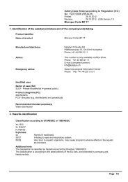
Energy Recovery<br />
The technology behind <strong>Katadyn</strong> reverse osmosis watermakers<br />
Reverse osmosis desalination was first developed over three decades ago. It was a major<br />
breakthrough in desalting technology, but the original process required a lot of power. By<br />
recovering 90% of the energy lost in conventional reverse osmosis systems, we’ve made small<br />
desalinators practical, so you can have freshwater when and where you need it.<br />
Conventional Reverse Osmosis Desalination<br />
The lower left portion of Figure 2 shows the basic principle of reverse osmosis desalination.<br />
When saltwater is forced through a<br />
semipermeable membrane at high<br />
enough pressure—typically 800<br />
psi—pure water will pass through<br />
the membrane, but salts will not.<br />
The membrane acts as a barrier to<br />
contaminants such as salts,<br />
viruses and bacteria, separating<br />
them from the pure water.<br />
When seawater is forced against a<br />
membrane, only 10% passes<br />
through as pure water. In a<br />
conventional system, the<br />
remaining waste brine stream, still<br />
under high pressure, passes<br />
through a pressure-reducing valve<br />
and is discharged overboard. For<br />
every gallon of pure water made,<br />
up to ten gallons of seawater must<br />
be pressurized! Therefore, 90% of<br />
the energy used in conventional<br />
reverse osmosis is lost!<br />
Energy Recovery Makes It Possible The upper right portion of Figure 2 illustrates<br />
how <strong>Katadyn</strong> systems are configured to recover and effectively re-use the energy wasted in<br />
conventional reverse osmosis. The waste brine stream contains up to 90% of the energy<br />
expended. By recovering this energy, we are able to dramatically reduce the power needed to<br />
desalt seawater.<br />
To do this, we developed and patented a high pressure energy recovery pump. It recycles the<br />
high-pressure brine by redirecting it to the backside of the pump’s piston. By balancing the<br />
opposing force on the piston’s front side, the brine provides a power assist to the pumping<br />
operation. Seawater can then be pressurized with much less effort.<br />
<strong>Katadyn</strong> Watermakers <strong>Katadyn</strong> watermakers are simple, energy efficient and easy to<br />
use and maintain. The <strong>PowerSurvivor</strong> <strong>80E</strong> incorporates the latest advances in watermaker<br />
technology, featuring an improved oil-bath drive assembly, an all-316 stainless steel pump<br />
body, and simplified construction for easier and less frequent maintenance.<br />
3
Installation<br />
Do it right the first time and reap the rewards<br />
The <strong>PowerSurvivor</strong> <strong>80E</strong> watermaker utilizes a low-volume, high-pressure, positive<br />
displacement pump. Unlike the centrifugal pumps found in some systems, a positive<br />
displacement pump is self-priming. It can also draw water when mounted several feet above<br />
the waterline of a vessel. Thus, the watermaker may be installed in almost any location and<br />
orientation.<br />
The most important part of a good installation is proper planning. Although the design and<br />
operating requirements of the <strong>PowerSurvivor</strong> <strong>80E</strong> allow much latitude for equipment location,<br />
there are several cautions and suggestions you should consider before proceeding with an<br />
installation.<br />
Installation DOs<br />
When choosing a location for the watermaker drive/pump or membrane assembly:<br />
Avoid areas with excessive heat. Ambient temperatures above 105° F (40° C) exceed<br />
the ratings for the electric motor, and excessive heat can damage or destroy the<br />
membrane.<br />
(Note: Most engine rooms get hotter than 105° F!)<br />
Choose a dry area. The motor/drive assembly is not waterproof and can corrode.<br />
Choose an area free of fuel vapors. The electric motor is not vapor-proof and should<br />
not be operated if explosive or flammable materials are present!<br />
Find a location which allows comfortable access for routine inspection and servicing.<br />
In addition, you should:<br />
Install the pre filter assembly in an easily accessible location. It needs regular<br />
(sometimes daily) inspection and maintenance. For ease of routine maintenance, the<br />
choice for this location is probably the single most important decision you will make—<br />
plan it carefully!<br />
Provide a shutoff valve or seacock in the seawater intake line.<br />
Install a coarse strainer in the seawater intake line.<br />
We recommend using properly sized ring terminals and a terminal strip near the pump<br />
to connect electric power. This allows for easy testing, removal and servicing when<br />
required.<br />
Installation DON’Ts<br />
Don’t use a thru-hull installed high on your vessel’s hull for your source of seawater<br />
intake. This is especially important for sailboats. Even a normal amount of heel when<br />
under sail can cause the thru-hull to be out of the water, allowing air into the intake<br />
system. A rolling anchorage can do the same.<br />
Don’t locate the pump assembly above gear or materials that could be damaged if it<br />
leaked.<br />
Don’t locate the pump assembly near to sleeping quarters, bunks, or other areas that<br />
are normally “quiet” areas for yourself or crew members.<br />
4
Installation Procedures<br />
Although every installation has its custom aspects,<br />
the following general instructions should be<br />
useful to the typical installer. Refer to Figure A-1<br />
(in the Appendix) for information on part identification<br />
and system connections.<br />
1. Install Pump: After reading the comments<br />
on the preceding pages, decide on a location for<br />
the pump and drive assembly. It should be<br />
mounted with the pump and drive side by side<br />
horizontally. The reason for this requirement is to<br />
avoid two problems:<br />
• If the pump develops a seawater leak and<br />
is located directly above the drive<br />
assembly, the drive assembly and/or<br />
electric motor may be damaged (Figure 3,<br />
left).<br />
• If the drive assembly develops an oil leak and is located directly above the pump, oil<br />
may find its way into the pumping system and damage the membrane (Figure 3, right).<br />
We recommend securely thru-bolting the pump/drive assembly to a sturdy bulkhead or<br />
platform, using corrosion-resistant 1/4" fasteners with flat washers (See Figure A-1). Pick a<br />
location that allows ample space for routing the required hoses and electrical wires to the pump<br />
and motor.<br />
2. Connect Electrical Power to<br />
Pump: To provide 12 (or 24) VDC electric<br />
power to the motor, use a minimum of 14<br />
gauge / 12 VDC (16 gauge / 24 VDC)<br />
stranded copper wire. We recommend 12<br />
gauge / 12 VDC (14 gauge / 24 VDC) or<br />
larger wire for distances over 20 feet. Tinned,<br />
stranded copper wire is preferred for marine<br />
installations and is available in most marine<br />
hardware stores. Figure 4 shows a typical<br />
electrical power configuration.<br />
3. Mount Pre filter Assembly and<br />
3-Way Valve: Lightly coat the male<br />
threads of the middle port of the pre filter 3-<br />
way valve with a non-hardening, paste-type<br />
thread sealant (e.g., Permatex ® ) to assure an<br />
airtight seal. (Note: Teflon tape is not<br />
recommended.)<br />
+<br />
red<br />
Basic Electrical Diagram<br />
black<br />
-<br />
Fuse and Circuit<br />
Breaker:<br />
12 V = 15 A<br />
24 V = 10 A<br />
12 V or 24 V<br />
Battery or Power<br />
Source<br />
Terminal<br />
Strip<br />
white<br />
black<br />
Dimension of the cable:<br />
14 gauge / 12 V<br />
16 gauge / 24 V<br />
M<br />
Figure 4<br />
1. Carefully thread the middle port of the pre filter 3-way valve into the “IN” port of the pre<br />
filter housing. Do not over tighten this connection. When assembled correctly, the long<br />
axis of the 3-way valve should be vertical (See Figure A-1).<br />
2. Fasten the supplied right-angled mounting bracket for the pre filter assembly to a<br />
bulkhead. Orient it so the pre filter assembly will be vertical, with the bowl underneath.<br />
We recommend that it be thru-bolted with corrosion-resistant hardware.<br />
3. Screw the top of the pre filter housing to the bracket with the supplied screws. One port<br />
of the pre filter 3-way valve should project above the housing through the notch in the<br />
mounting bracket.<br />
5
4. Install Seawater Intake Plumbing: There are two common approaches to<br />
providing the seawater intake circuit:<br />
• Tee into an existing seawater intake (e.g., engine cooling water or manual seawater<br />
pump inlet).<br />
• Install a dedicated thru-hull for the watermaker.<br />
Either of these configurations should meet the following criteria:<br />
• It should be at a low point on the vessel’s hull, to minimize the chance of air intake<br />
during heeling or rough conditions.<br />
• The thru-hull should be a minimum of 1/2" I.D., and possibly larger if it is a shared inlet.<br />
(Note: If there is the possibility that in the future you will want to upgrade by adding a<br />
second <strong>PowerSurvivor</strong> <strong>80E</strong> to implement redundant systems—you should consider<br />
substituting 5/8" I.D. hoses and hose fittings during your initial installation).<br />
• An easy-to-reach seacock should be installed on the thru-hull immediately inside the<br />
hull.<br />
• A coarse seawater strainer is strongly recommended. It should be easy to reach and<br />
clean.<br />
The easiest and most commonly used approach is to tee into an existing seawater intake<br />
system. Because the flow rate and volume of seawater intake for the <strong>PowerSurvivor</strong> <strong>80E</strong> are<br />
both extremely low, the pump can be adequately supplied by most pre-existing intakes—even<br />
inlets that operate at modest negative pressures, such as the cooling water inlet for an engine<br />
or generator.<br />
When teeing into an existing seawater supply, we recommend installing a separate seacock or<br />
valve (in addition to the one at the thru-hull) to independently control the supply to the<br />
watermaker.<br />
5. Install Reject Brine Plumbing: The reject brine water can be teed into an existing<br />
scupper or sink drain hose for draining overboard. Use the 1/2" reinforced hose and supplied<br />
hose clamps. A tee of the correct size will have to be supplied. Alternatively, a dedicated thruhull<br />
may be installed at a convenient location. In this case, we recommend that a seacock be<br />
installed at the thru-hull.<br />
6. Install Product Freshwater Plumbing: Your product freshwater plumbing<br />
design should allow for both saving and discarding of product freshwater. This normally<br />
requires (1) a container for collecting good product freshwater and (2) a drain location.<br />
In no case should the product freshwater hose be permanently plumbed into the ship’s potable<br />
water storage tank(s), without providing a way to reject the product freshwater when necessary.<br />
Note that product freshwater should always be rejected during the first few minutes after<br />
startup, and especially after treating with membrane preservative or chemical cleaners. For that<br />
reason alone, a means must be provided for disposing of unwanted product freshwater.<br />
In general, we do not recommend that the output of product freshwater be routed directly into a<br />
vessel’s freshwater storage tank(s). If for any reason the watermaker should fail during<br />
operation, there is a good chance that the entire supply of freshwater in the storage tank could<br />
become contaminated by unpurified seawater. This is especially important if:<br />
• you have only a single tank for storing potable water.<br />
• you will be making extended offshore passages and depend on your watermaker for<br />
your potable water supply.<br />
6
The preferred method for collecting product freshwater is to use portable jerry jugs or a<br />
separate “day tank,” which is isolated from the main storage tank. Some method should be devised<br />
for testing the product freshwater quality at the beginning and at the end of each<br />
operation. When you are certain that the quality of the collected product freshwater is<br />
acceptable, it can be transferred to the main storage tank.<br />
Note: The important concept is to always have a minimum quantity of known-good potable<br />
water available at all times, either in your main storage tank or in the collection container(s).<br />
The length of your expected voyage and maximum distance from a source of potable water<br />
will determine the size of the adequate minimum amount. Arrange your watermaking<br />
schedule to assure that you always have the minimum of known-good potable water on<br />
board in one or both of your containers.<br />
To route the product freshwater output of their watermakers, many users simply run the 1/4"<br />
I.D. clear plastic hose directly from the output hose barb on the membrane housing to a single<br />
location, where the water is tested and either discarded or run into a collection container.<br />
Should you prefer to have your product freshwater output routed to two separate locations for<br />
testing/discarding and collection, the watermaker system includes a product 3-way valve for<br />
use in your output plumbing. Refer to Figure A-1 for a routing diagram.<br />
Using your Watermaker<br />
Watermakers like to be run often<br />
The ease of operation of our watermakers has its roots in our original products, which were<br />
designed as military-quality survival equipment. Our deep experience in this technology,<br />
combined with many years of active user feedback, allowed us to design a watermaker that can<br />
be operated with little or no technical knowledge. There are no complicated adjustments to<br />
make or gauges to monitor. By following the instructions below and paying attention to system<br />
maintenance, you can expect years of trouble-free operation.<br />
Pre-Run Checklist: Before running your<br />
watermaker, always check the following:<br />
Any valves in the seawater intake, reject brine and<br />
product freshwater lines should be open.<br />
The prefilter 3-way valve should be in the position to<br />
intake seawater.<br />
Assure that the product freshwater output is routed to<br />
a drain for testing/discarding.<br />
Make sure the clean/run valve lever on the pump is in<br />
the “run” position (See Figure 5).<br />
Check for bad (“rotten egg”) smell from the water in<br />
the prefilter assembly. Replace the element and clean<br />
the housing, as required. Also check for foul water in<br />
any in-line coarse strainer.<br />
Check battery or power supply voltage. Operating your watermaker below about 11 VDC is<br />
hard on the electric motor and dramatically reduces the output of product freshwater.<br />
Observe the seawater around your vessel. Is it clean enough to use for your seawater<br />
intake There are several things to avoid feeding to your watermaker:<br />
7
• petroleum products, such as oil, fuel, thinners, paints, paint removers, etc.<br />
• chlorine-treated water (for example, most “dockside” water)<br />
• silty water—water contaminated by fine, hard, suspended particulates<br />
• putrid water, “red tides”, or any seawater that smells or looks contaminated<br />
It is important to remember that the watermaker is designed to process clean, open-ocean<br />
seawater. Any departure from that standard for your seawater intake runs the risk of causing<br />
excessive wear or damage to internal pump parts and/or the vulnerable reverse osmosis<br />
membrane, or producing contaminated product freshwater.<br />
Note: Judging the quality of seawater input always involves a certain calculated risk. We<br />
know of watermaker systems that have been destroyed far offshore by intaking fresh whale<br />
excrement or oil contaminants from natural seepages—still, the chance of such things<br />
happening is normally small. On the other hand, regularly running a watermaker in an<br />
enclosed marina or harbor runs a much higher risk of harmful contamination. If you need to<br />
test a new installation while in a marina or harbor, monitor the water quality around your<br />
vessel carefully while testing. Most of the time you should be able to run the watermaker<br />
safely for enough time to check out the system. Don’t sail away without testing a new<br />
installation or repair!<br />
Startup: Turn on the electric power to the watermaker. If there is air in the seawater intake<br />
plumbing, the pump may require several minutes to draw up enough water to fill the hoses,<br />
prefilter housing, pump and membrane housing. Since the pump is self-priming, there is no<br />
need to prime the system prior to running. Shortly after the hoses and prefilter housing have<br />
filled with seawater, reject brine water should start discharging from the pump.<br />
Test and Run: When all air has been forced out of the system (which may take several<br />
minutes more), product freshwater should begin to flow from the hose barb at the end of the<br />
membrane housing. It is normal for product water to be unpotable for a short time after startup.<br />
Reject the initial product water and use the TDS meter and/or taste test to monitor the quality<br />
until it is acceptable. This will usually take about 5–10 minutes. When good quality water is<br />
flowing continuously, direct the product freshwater output to your freshwater collection tank.<br />
Continue to run until the desired quantity of water has been produced.<br />
Shutdown and Storage: When the desired amount of water has been produced, the<br />
product freshwater quality should be checked again. If water quality is good at both the<br />
beginning and end of the run, it is likely that the collected water is good and can be safely<br />
transferred to the ship’s potable water storage tank.<br />
If you plan to run the watermaker again within a couple of days, it can simply be turned off. If<br />
you do not intend to use your watermaker again within a week, it should be treated with<br />
membrane preservative to prevent organic growth on the membrane.<br />
8
Note: Organic growth is much more rapid in warm or tropical climates. If using the<br />
watermaker in a tropical environment, we recommend a membrane preservative treatment if<br />
the watermaker will not be run again within the next three days! Before doing repairs or<br />
maintenance work on a <strong>PowerSurvivor</strong>, close the seawater inlet valve after turning<br />
off the system. Otherwise, the possibility exists that hose failure, for example, could<br />
cause the boat to sink.<br />
At the end of a watermaker run, check the condition of water in the prefilter housing. If there is<br />
evidence of trapped material, clean the prefilter housing and install a clean prefilter element.<br />
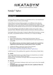
Special Conditions<br />
Product freshwater output volume will vary depending on the salinity and temperature of the<br />
seawater being processed. Figure 6 illustrates the relationship between feed water<br />
temperature and the quantity of product water.<br />
Factors which are known to affect output or performance<br />
include:<br />
• High Salinity will decrease output<br />
slightly and lead to a modest increase in<br />
current draw. Effectively, the pump must<br />
work harder to remove a larger<br />
percentage of dissolved solids from the<br />
seawater.<br />
• Cold Water will have an effect similar to<br />
that of high salinity.<br />
• Silt or Sand can damage the membrane<br />
and internal pump components if not<br />
removed during prefiltration. If you must<br />
regularly process such water, consider<br />
installing a Silt Reduction Kit (see Kits<br />
& Accessories).<br />
• Foul Intake Seawater can seriously effect the quality of the product freshwater. The<br />
watermaker membrane is designed to remove the impurities found in clean, open ocean<br />
seawater. Processing of seawater with other kinds of impurities (1) may not remove<br />
those impurities and (2) may damage or destroy the membrane. See Maintenance and<br />
Service: Prefilter Maintenance below for more information on typical problems<br />
associated with foul water intake.<br />
• Low Battery Voltage will dramatically reduce the volume of seawater throughput and<br />
product freshwater output. We recommend not operating the watermaker if battery<br />
voltage is below 11 VDC.<br />
Note on Red Tides: In many areas of the ocean, a phenomenon generally known as a<br />
“red tide” can occur. This generic name is used to describe an invasion of local waters by<br />
huge populations of micro-organisms, which turns the seawater red. Occasionally, a red tide<br />
is accompanied by the death of local fish and other sea life, which can cause serious local<br />
pollution of the seawater. Although the watermaker membrane can remove the<br />
microorganisms that cause the red tide, it can not remove all of the chemical pollutants<br />
caused by large-scale biological decomposition. Therefore, we do not recommend using the<br />
watermaker to process seawater when a red tide is present.<br />
9
Maintenance and Service<br />
A little love goes a long way<br />
We’ve worked hard to design a product that is simple to operate and maintain. However,<br />
regular attention to the few maintenance requirements of this equipment is critically important.<br />
This section of the Owner’s <strong>Manual</strong> describes both the routine and the long-term maintenance<br />
requirements of the <strong>PowerSurvivor</strong> <strong>80E</strong>. Much of our knowledge of maintenance requirements,<br />
watermaker per-formance, and potential problems is a result of feedback from actual users over<br />
many years. Following these instructions will help keep your product freshwater quality good<br />
and your watermaker running trouble-free.<br />
Pump Maintenance<br />
Once properly installed, the watermaker pump and drive assembly require little attention. You<br />
should regularly inspect the equipment and check for any leakage of seawater or oil leaks from<br />
the drive assembly. Any leakage of oil or seawater is a sign of a problem and should be<br />
corrected.<br />
Make certain that the watermaker remains dry. Exposure to saltwater can cause corrosion of<br />
the drive assembly and/or damage to the electric motor. Keep all electrical connections clean,<br />
dry and tight.<br />
After every 1000 hours (approximately) of use, replace the seals in the pump (See Seal<br />
Replacement below). After approximately 5000 hours of use, have the electric motor inspected<br />
for brush wear and commutator condition.<br />
Pump Piston Shaft Lubrication: It is important to lubricate the pump piston shaft<br />
periodically, especially after cleaning the membrane. The piston shaft is visible at the side of<br />
the drive assembly, where the pump connects to<br />
the drive (see Figure 7). Jog run the watermaker<br />
and stop it when the piston shaft is at its point of<br />
farthest travel away from the pump (i.e., towards<br />
the drive assembly). Assure that the watermaker<br />
is off and can not be started accidentally while<br />
you work. Clean the exposed piston shaft with a<br />
clean rag and lubricate the shaft with nonpetroleum<br />
silicon lubricant.<br />
Warning: The <strong>PowerSurvivor</strong> <strong>80E</strong><br />
motor should be turned off and<br />
disconnected from its source of power<br />
before attempting to lubricate the piston<br />
shaft. Never put your fingers into the area<br />
of the piston shaft while the motor is<br />
running. This could result in serious<br />
injury.<br />
10
Prefilter Maintenance<br />
Background: Maintaining a healthy watermaker largely involves taking proper care of the<br />
prefilter assembly and seawater intake plumbing. Failure to do so is the most common cause of<br />
the two most frequent types of watermaker “failure” we hear about: (1) producing diminished or<br />
no freshwater output, or (2) producing “bad-smelling” product freshwater. Here is what happens:<br />
No Freshwater Output: The most common cause of diminished or no product<br />
freshwater output is air entering the seawater intake system at some point. The pump volume is<br />
small and the pressure required to press water through the membrane is high (about 800 psi).<br />
Since air is highly compressible, a very small amount of air can keep the pump from producing<br />
enough pressure to produce product freshwater. Periodically inspect and test the entire<br />
seawater intake system to assure that all joints and fittings are airtight, especially the<br />
connections at the prefilter assembly. (Note: Be aware that a stable air gap at the top of the<br />
prefilter housing while operating is not uncommon, and doesn’t necessarily mean that air is<br />
getting to the pump itself.)<br />
Bad-smelling Product Freshwater: The purpose of the prefilter assembly is to trap<br />
any particulates in the intake seawater that are larger than 30 microns. A coarse strainer (if<br />
installed) performs the same chore for contaminants of larger size. In each case, trapped<br />
material remains in the prefilter housing (and/or strainer bowl) until removed.<br />
Much of the trapped material is organic: plankton, seaweeds and flotsam of all types. After a<br />
watermaker has been turned off, this material soon begins to decompose. As it does, it breaks<br />
down into a number of chemicals composed of smaller molecules. Some of these molecules are<br />
small enough to pass through the watermaker membrane along with the product freshwater.<br />
Perhaps the best-known example of such a chemical is hydrogen sulfide, a gas which (in small<br />
concentrations) smells like “rotten eggs.”<br />
Two main factors affect the speed with which these products of organic decomposition will<br />
contaminate a watermaker system: (1) the ambient temperature and (2) the quantity of trapped<br />
material. We realize that many users of our equipment run their watermakers in near-shore<br />
situations while anchored. The amount of trapped material is usually high in such locations, and<br />
the prefilter assembly will require more frequent attention. Moreover, the high ambient<br />
temperatures in tropical locations greatly accelerate the rate of the decomposition process.<br />
The following maintenance routine for the prefilter assembly is appropriate for a “worst case”<br />
scenario: using the watermaker in a near-shore location in the tropics. Users in temperate<br />
climate areas or users processing open-ocean seawater during offshore passages are not as<br />
likely to require the same diligence.<br />
Prefilter Maintenance: At the end of each run of your watermaker, examine the prefilter<br />
assembly (and the coarse strainer, if installed) for trapped material. If anything is visible,<br />
perform the following procedure:<br />
11
1. Unscrew the prefilter housing, remove the dirty<br />
prefilter element, and discard the water in the<br />
bowl. Do not lose the large o-ring at the top of<br />
the bowl.<br />
2. Clean the inside surface of the prefilter bowl.<br />
Inspect and clean the o-ring at the top of the<br />
bowl. Lubricate the o-ring and the threads of<br />
the prefilter housing with a light coat of silicon<br />
grease.<br />
3. Install a clean filter element and screw the<br />
prefilter bowl back on securely.<br />
4. If the watermaker will not be used within the<br />
next three days, treat it with membrane<br />
preservative (see Membrane Storage below).<br />
5. Tie a line through the center of the dirty filter<br />
Warning: If you purchase aftermarket<br />
filter elements, be certain<br />
they are made from polyester fibers.<br />
In particular, be wary of elements<br />
made of paper materials. They look<br />
very similar, but are designed for<br />
use with other types of water purification<br />
systems and are harmful to<br />
the membranes and high pressure<br />
pumps used in reverse osmosis<br />
watermakers. Be certain you<br />
purchase only polyester filter<br />
elements of 30-micron (or finer) size.<br />
element and, if underway, tow it behind the vessel for a few minutes. If the vessel is<br />
anchored, hang the dirty filter over the side of the boat so that it is underwater, and<br />
jerk/shake it up and down a few times to dislodge the contaminants.<br />
6. Dry the filter element thoroughly, preferably in the sun. Then store it for use as a clean<br />
filter the next time the prefilter assembly is serviced.<br />
We do not recommend scrubbing filter elements with brushes or other abrasive tools or<br />
materials, as such treatment is unnecessary and greatly shortens the life of the filter element. If<br />
filter elements are cleaned regularly as directed, and not allowed to become extremely dirty,<br />
they can be expected to last for many months of service with nothing more than the gentle<br />
cleaning described above. Clean filter elements also help assure unrestricted flow of intake<br />
seawater to the pump.<br />
Membrane Storage, Preserving & Cleaning<br />
The two reverse osmosis membrane elements inside the membrane housing are expensive and<br />
delicate components of your system. When properly cared for, they can be expected to last for<br />
several thousand hours of use. However, improper use, maintenance or handling can damage<br />
or destroy them very quickly.<br />
Membrane Preservative Treatment: The primary<br />
purpose of a membrane preservative treatment is to keep<br />
membrane moist and reduce biological growth on the<br />
membrane surface. Over time, biological matter can adhere to<br />
the membrane surface, thus gradually decreasing its<br />
effectiveness. When the watermaker is not to be used for an<br />
extended period of time, you should preserve the membrane.<br />
A membrane preservative treatment is effective for<br />
approximately one year (storage temperature
In temperate climates, the maximum period of time the watermaker should be stored without<br />
preserving the membrane is approximately one week. In hot or tropical climates, the<br />
watermaker membrane should be preserved if it will not be used within the next three days.<br />
Follow these directions to preserve the membrane of your watermaker:<br />
1. Turn the Clean/Run Valve lever on the pump to its “Clean” position (see Figure 8).<br />
2. Fill a clean plastic container or bucket with two quarts (approximately 2 liters) of clean<br />
water. Freshwater is preferable, but clean seawater may be used if freshwater is not<br />
available. (Caution: Never use chlorinated freshwater. This may damage the<br />
membrane.)<br />
3. Mix two spoonfuls (approximately 20 grams, or 1% by weight) of dry Membrane<br />
Preservative chemical with the water in the container and stir until completely dissolved.<br />
4. Use your product 3-way valve (or move the product water output hose) to be sure that<br />
any water flowing from the product freshwater output is properly discarded.<br />
5. Turn the lever on the prefilter 3-way valve to the alternate intake position. Run the 1/4"<br />
alternate intake hose with the strainer attached into the container of membrane<br />
preservative solution.<br />
6. Turn on the watermaker and run it until almost all of the membrane preservative has<br />
been drawn from the container and foamy membrane preservative solution is ejecting<br />
from the reject brine hose. If there is a chance that the watermaker will be subjected to<br />
freezing conditions, continue to run until air is being ejected from the reject brine hose.<br />
(Note: If the membranes freeze, they must be slowly and completely thawed before the<br />
watermaker may be used again.)<br />
7. Turn off the watermaker. It is now ready for storage for up to one year.<br />
If seawater was used instead of freshwater, repeat the membrane preserving procedure with<br />
freshwater as soon as possible. Repeat the above procedure at least once a year if the<br />
watermaker is not being operated.<br />
Cleaning the Membrane: We do not recommend casual or regular cleaning of the<br />
reverse osmosis membranes in the watermaker—it should only be done when needed. Under<br />
normal use conditions, when only open-ocean seawater is being processed, cleaning the<br />
membranes should rarely (or never) be necessary. Proper membrane<br />
preservative treatments prior to extended periods of non-use will<br />
reduce biological growth on the membrane surface. Under these<br />
conditions and with proper care, a membrane can be used for years<br />
without requiring a cleaning.<br />
Cleaning the membranes is only necessary if contaminants are<br />
deposited on, and adhere to, the membrane surface in sufficient<br />
amounts to affect the output of product freshwater. Usually this<br />
condition also causes battery current to increase. There are two main<br />
types of such deposits and a different chemical cleaner is needed for<br />
each type:<br />
Note: Buildup of<br />
deposits and reduction<br />
in product freshwater<br />
flow usually take place<br />
gradually over<br />
extended periods of<br />
time. Sudden reduction<br />
or stopping of product<br />
water output is rarely<br />
caused by a dirty<br />
membrane.<br />
• Organic Growth—usually caused by processing<br />
brackish water or failure to properly store a membrane during extended periods of<br />
non-use. Use Alkaline Cleaner.<br />
• Mineral Scale—caused by mineral impurities in the intake water supply. Use<br />
Acid<br />
Cleaner.<br />
13
The only indication that the membranes might benefit from cleaning is a substantial reduction in<br />
the quantity of product freshwater output, all other factors being normal (e.g., battery voltage,<br />
salinity, seawater temperature). The best way to detect such a problem is by keeping an<br />
accurate log of product freshwater output at known battery voltages. Such a practice is highly<br />
recommended.<br />
If you have determined that your membranes need cleaning and you know the type of deposits<br />
(mineral or organic), use the appropriate cleaner. If you do not know the nature of the deposits,<br />
try cleaning first with the Alkaline Cleaner and check for improvement in product<br />
freshwater output. If output remains poor, repeat the cleaning process using the Acid<br />
Cleaner. Never mix the two types of cleaners! Always flush well with clean water between<br />
processes if performing both alkaline and acid cleaning. The following directions apply for both<br />
types of membrane cleaners:<br />
1. Turn the clean/run valve lever on the pump to its “clean” position (see Figure 8).<br />
2. Discard any dirty seawater in the prefilter assembly. Clean the housing and install a clean<br />
element<br />
3. Fill a clean plastic container or bucket with one gallon (approximately 4 liters) of clean<br />
water. Freshwater is preferable, but clean seawater may be used if freshwater is not<br />
available. (Caution: Never use chlorinated freshwater. This may damage the<br />
membrane.)<br />
4. Mix four spoonful (approximately 40 grams) of either Acid Cleaner or Alkaline Cleaner<br />
(not both!) with the water in the container and stir until the cleaner is completely<br />
dissolved. The water should be warm, but not over 120° F (49° C).<br />
5. Turn the lever on the prefilter 3-way valve to the alternate intake position. Run the 1/4"<br />
alternate intake hose with the strainer attached into the container of cleaning solution.<br />
6. Disconnect the reject brine water hose from its drain (or use a separate length of hose) to<br />
route the reject brine water back into the container of cleaning solution during the<br />
following procedure.<br />
7. Turn on the watermaker. Discard any solution coming from the reject brine hose for about<br />
30 seconds. Then run the reject brine water hose back into the container of cleaning<br />
solution to allow recirculation of the cleaner.<br />
8. Continue to run the watermaker for about 15 minutes, to assure that the cleaning solution<br />
is well circulated through the pump and membrane housing.<br />
9. Turn off the watermaker and allow the membranes to soak in the cleaning solution for 5<br />
to 10 hours, or overnight. For severe fouling, repeat Steps 8 and 9 of this procedure.<br />
10. When the soaking is finished, remove the reject brine hose from the cleaning solution<br />
container and run the watermaker again. Discard the first pulses of the reject brine water.<br />
When the reject brine flow becomes cleaner, return the reject brine hose to the cleaning<br />
solution container for recirculation.<br />
11. Continue to run the watermaker and recirculate the cleaning solution for another 30 to 60<br />
minutes<br />
12. When cleaning is complete, turn off the watermaker. Reconnect the reject brine hose to<br />
its normal drain location.<br />
13. Remove the alternate intake hose and strainer from the cleaning solution and place them<br />
into a container of clean, warm (non-chlorinated) freshwater. If freshwater is not<br />
available, clean seawater may be used if its temperature is above 68° F (20° C).<br />
14. Turn on the watermaker and flush warm water through the system for 5 minutes.<br />
If the watermaker will be stored for more than a week (three days in warm climates), it should<br />
now be treated with the membrane preservative solution.<br />
14
Seal Replacement<br />
After approximately every 1000 hours of use, the watermaker should be partially disassembled,<br />
cleaned, and lubricated with non-petroleum silicon grease. At that time, the seals should be<br />
inspected and replaced, as required. The standard Repair Seal Kit (included in the Extended<br />
Cruising Kit—see Kits and Accessories) is available from <strong>Katadyn</strong> and most marine retail stores.<br />
It includes a complete set of replacement seals and other components for all user-serviceable<br />
parts of the watermaker.<br />
It is unlikely that you will have to replace all of the seals contained in the kit at every servicing.<br />
The dynamic seals work harder and wear faster than others, and will need to be replaced more<br />
often. Seals will wear faster in watermakers that are operated in silty or high salinity water. We<br />
recommend that you save old seals. Most of them are still useable and could be kept in a kit for<br />
emergency repairs.<br />
Preparation: Before beginning to disassemble the watermaker, read the following<br />
instructions completely. Have a Repair Seal Kit on hand. Before commencing work, refer to the<br />
full-size drawings in Figures A-3 and A-4 in the Appendix to identify the parts contained in the<br />
kit and make sure none are missing. Prepare a clean flat workspace with good lighting. Have<br />
the following tools and materials available for a complete rebuild:<br />
Tools Needed<br />
piston seal installation tool<br />
needle-nosed pliers<br />
1/2" open-end wrench small standard pliers<br />
11/16" open-end wrench small scissors<br />
7/8" open-end wrench soft mallet<br />
1/4" allen wrench 10x loupe or magnifier<br />
medium flat blade screwdriver<br />
silicon grease<br />
clean rags<br />
15
Disassembly:<br />
1. Before beginning disassembly, run the watermaker and stop it when the piston shaft is at its<br />
farthest point of travel away from the pump (toward the drive assembly). This provides<br />
enough room for sliding the rubber boot<br />
back toward the pump in Step 3.<br />
2. Use the 11/16" open-end wrench to<br />
disconnect the two high-pressure hoses<br />
(coming from the membrane housing)<br />
from the tube connectors on the check<br />
valve plate and the valve assembly.<br />
Loosen the hose clamps and remove the<br />
reinforced plastic seawater intake and<br />
reject brine hoses. See Figure R-1.<br />
3. Use the 1/2" open-end wrench to remove<br />
the four hex nuts securing the pump<br />
back plate to the drive assembly. Then<br />
pull the pump away from the drive<br />
assembly to expose as much of the<br />
piston shaft as possible. Slide the black<br />
rubber boot on the piston shaft toward the<br />
pump to expose the shaft coupling pin. Use<br />
a small screwdriver or allen wrench to push<br />
the coupling pin out of the shaft. (Note: the<br />
coupling pin is a loose fit and may fall out on<br />
its own. Do not lose it.) Separate the pump<br />
from the drive assembly and set the drive<br />
assembly aside in a safe place. Slide the<br />
black rubber boot off the piston shaft. Move<br />
the pump to a clean work surface for further<br />
disassembly. See Figure R-2.<br />
4. Remove the plastic intake hose barb from<br />
the check valve plate. While the pump is still<br />
bolted together, use the 7/8" open-end<br />
wrench to just loosen the tube fitting in the<br />
check valve plate. Then use the 1/4" allen<br />
wrench to remove the six socket head<br />
flange bolts that hold the check valve plate<br />
to the pump body. Separate the check valve plate from the pump body and remove the<br />
large o-ring (8012830) seal between them. See Figure R-2.<br />
16
5. Disassemble the two check valve assemblies. Use the needle nose pliers to lift the intake<br />
valve retainer, valve spring and poppet valve out of their bore in the inside surface of the<br />
check valve plate. Remove the tube fitting, reject check valve retainer, valve spring and<br />
poppet valve from their bore in the outside surface of the check valve plate. To remove the<br />
valve seats, use an allen wrench (or similar flat-ended tool) to push each valve seat out of<br />
its bore, working from the opposite side of the bore from which the rest of the valve<br />
assembly was removed. See Figure R-3.<br />
6. Separate the pump back plate from the pump body by first using the 1/4" allen wrench to remove<br />
the four socket head flange bolts that hold them together. It is unlikely that the two<br />
parts will separate easily. Insert the wide end of the piston seal installation tool into the<br />
pump body cylinder from the check valve side of the pump body until it contacts the<br />
exposed end of the piston. Use a soft mallet to tap the small end of the installation tool and<br />
drive the piston and pump back plate away from the pump body. When the back plate has<br />
separated from the pump body, pull the piston out of the back body and remove the two old<br />
o-rings (8012830) and (8012444). Be careful not to lose the large relief valve spring that is<br />
exposed when the pump parts separate.<br />
7. Remove the old PIP ring and cup seal<br />
from the piston. One method to<br />
accomplish this is to wedge a small<br />
screwdriver underneath the cup seal<br />
and pry it up far enough that it can be<br />
cut with a pair of small scissors or a<br />
razor blade. Repeat the process for<br />
the PIP ring.<br />
8. Remove the wiper block from the<br />
pump back plate, and use a pair of<br />
needle-nose pliers to pull the old<br />
wiper block seal out of the wiper<br />
block. Remove the spacer washer, if<br />
present. Working from the side of the<br />
back plate that faces the pump body, use a flat-ended tool or a small socket on an<br />
extension to press out the two backup washers, two piston shaft seals and shaft bushing<br />
from the back plate. Refer to Figure R-4. This completes the disassembly of all userserviceable<br />
parts of the <strong>Katadyn</strong> <strong>PowerSurvivor</strong> <strong>80E</strong> watermaker.<br />
17
Reassembly: Before you begin reassembly of the watermaker, clean all parts using clean,<br />
lint-free rags. At this time, all parts should be carefully inspected for wear or damage. Use a 10x<br />
magnifier or loupe to examine the seals, o-rings and other small parts. Stubborn rust stains and<br />
deposits on metal parts may be cleaned with a soft-metal wire brush (e.g., stainless steel or<br />
brass). Do not use polishes, cleaning compounds containing abrasive materials, or regular steel<br />
wire brushes. Refer to the exploded drawing of the pump in Figure A-2 in the Appendix<br />
for the location of parts and seals during reassembly. Refer to Figures A-3 and A-4 in<br />
the Appendix for full-size drawings and identification of the components included in the<br />
Repair Seal Kit. In the following procedure, references to the Repair Seal Kit will be<br />
abbreviated to “RSK.” It will be assumed that all o-rings, seals, and mating surfaces<br />
have been lightly lubricated with non-petroleum silicon grease (supplied with the RSK).<br />
Warning: Use only non-petroleum silicon grease to lubricate your watermaker. Lubricants<br />
with a petroleum base will damage several watermaker components, including the reverse<br />
osmosis membrane. Be especially cautious of lubricants that “contain” teflon, silicon, etc.—<br />
such products could also contain petroleum-based components. An ample supply of silicon<br />
grease is included with each RSK.<br />
1. Refer to Figure R-5 during the following procedure. Place the piston assembly on a flat,<br />
stable surface with the shaft pointing up. Slide the installation tool (provided in the RSK)<br />
over the piston shaft with the wide end down. Lubricate the new PIP ring, cup seal and the<br />
installation tool with silicon grease. With the grooved side facing up, slide the PIP ring down<br />
the installation tool and onto the piston. Repeat this process for the cup seal. Note that the<br />
grooved side of the cup<br />
seal should be facing<br />
down; i.e., the grooved<br />
sides of the PIP ring and<br />
the cup seal should be<br />
facing each other. When<br />
finished with the<br />
installation, remove the<br />
installation tool from the<br />
piston shaft.<br />
2. To install the check valve<br />
components, refer to<br />
Figure R-3. Locate the<br />
two new check valve<br />
seats in the RSK.<br />
Observe that the hole in<br />
the center of each valve seat has a beveled edge on one side. Use your finger to press a<br />
valve seat into the bore for the reject check valve assembly. The seat should be pressed all<br />
the way in, with the beveled side of the valve facing outward (that is, against the end of your<br />
finger). Use the same technique to install the other valve seat in the bore for the intake<br />
check valve assembly. It too should be installed with the beveled edge of the valve seat<br />
facing outward, or against your finger.<br />
18
3. With its cross side facing down (facing the valve seat), lower a new poppet valve into the<br />
bore for the reject check valve. The poppet valve should be level and in the center of the<br />
valve seat at the bottom of the bore. Observe that one end of the valve retainers has a<br />
shallow hole that is the same diameter as the valve spring. Press a new spring into the hole<br />
in one of the retainers. When installed correctly, the spring should stay in the valve retainer<br />
when it is inverted. Lower the spring and valve retainer into the reject check valve bore with<br />
the spring facing the poppet valve. Make sure the tube fitting still has an o-ring installed and<br />
then screw it into the reject check valve hole and tighten securely with the 7/8" open-end<br />
wrench. Test your installation by inserting a small screwdriver into the hole for the reject<br />
check valve on the side of the check valve plate opposite the tube fitting. The reject poppet<br />
valve should move up and down slightly.<br />
4. Screw the plastic intake hose barb into the check valve plate (See Figure R-2). Then,<br />
working from the other side of the check valve plate, install a new poppet valve, valve spring<br />
and valve retainer, using the same procedure<br />
as was used for the reject check valve<br />
assembly. Lubricate a new o-ring (8012830)<br />
with silicon grease and install it into its groove<br />
in the pump side of the check valve plate.<br />
5. Taking care that the intake check valve<br />
components do not fall out of their bore, bring<br />
the check valve plate and the pump body<br />
together, align them, and install the six socket<br />
head flange bolts to hold the assembly<br />
together. Tighten these fasteners snugly. (If a<br />
torque wrench is available, tighten to<br />
approximately 120–140 in.-lbs.) Use a pencil<br />
eraser or small screwdriver to test the action<br />
of the intake poppet valve. See<br />
Figure R-6.<br />
6. Lubricate the inside of the cylinder in<br />
the pump body with silicon grease.<br />
Insert the piston assembly through<br />
its hole in the pump back plate and<br />
slide it as far as it will go toward the<br />
pump back plate, as shown in<br />
Figure R-7. Install the two o-rings<br />
(8012830) and (8012444) in their<br />
grooves in the pump back plate.<br />
Make sure the relief valve spring is<br />
installed in the pump body. Bring the<br />
pump back plate and pump body<br />
together carefully, first guiding the<br />
piston into the cylinder in the pump body, and then pressing the back plate as close as<br />
possible to the pump body. Install the four sockethead flange bolts and tighten snugly<br />
(approximately 120–140 in.-lbs.)<br />
19
7. Refer to Figure R-8. Slide one backup washer over the piston shaft and down into the shaft<br />
bore in the pump back plate. Slide one of the shaft seals over the end of the piston shaft<br />
with its flared side (the side<br />
with an embedded o-ring)<br />
facing the pump back plate.<br />
Slide it down the shaft and<br />
gently work it into the shaft<br />
bore. In-stall the second<br />
shaft seal in exactly the<br />
same way, with its flared<br />
side also facing the pump<br />
back plate. Work it into the<br />
shaft bore and press both<br />
seals in until the back of the<br />
second seal is about flush<br />
with the top of the shaft<br />
bore. Next, slide on the<br />
second backup washer,<br />
followed by the white plastic<br />
piston shaft bushing. Finally, slide the piston installation tool onto the piston shaft, small<br />
end first, and use it to push the backup washers, piston shaft seals and bushing all the way<br />
into the shaft bore, until the outside face of the bushing is flush with the top of the shaft<br />
bore. Remove the piston installation tool. If it was present when you disassembled the<br />
pump, install the thin plastic spacer washer.<br />
8. Press a new wiper block seal into the groove in the center of the wiper block. Squeeze the<br />
seal into an oval and start one edge into the groove. Then work the rest of the seal in until it<br />
seats evenly inside the wiper block bore. Slide the wiper block onto the piston shaft and<br />
press it down into the cavity in the pump back plate. The side of the wiper block from which<br />
the seal was installed should face outward. Slide the black rubber boot onto the piston<br />
shaft. Its flat side should face the pump.<br />
9. Place the assembled pump next to the drive unit and check the alignment of the coupling<br />
pin hole in the end of the piston shaft. Insert an allen wrench or small screwdriver through<br />
the coupling pin hole and use it to rotate the shaft until it will align with the hole in the slider<br />
shaft of the drive assembly. Bring the drive assembly and pump together carefully and,<br />
when the holes in the piston shaft and the slider shaft are aligned, press the coupling pin<br />
through the holes and slide the rubber boot over the coupling pin to hold it in place. Install<br />
the four hex nuts on the studs projecting through the flange on the drive unit and tighten<br />
them securely.<br />
10. Refer to Figure R-1 and install the two high pressure hoses, the seawater intake hose and<br />
the reject brine hoses to the pump assembly. Tighten the hoses clamps on the two<br />
reinforced plastic hoses. This completes the procedure for reassembly of the watermaker.<br />
When operation is commenced again, carefully check for any leaks or other signs of<br />
incorrect assembly.<br />
20
Troubleshooting Flowchart<br />
Use the flow chart below to diagnose and solve the most common problems associated with<br />
use of the <strong>PowerSurvivor</strong> <strong>80E</strong> watermaker. The information in this chart is a distillation of the<br />
experience of many users, our field representatives, and customer support staff. Use it first if<br />
you encounter a problem. If the problem persists, our Customer Support department is ready to<br />
help.<br />
21
Appendix<br />
A collection of useful information for the <strong>Katadyn</strong> watermaker owner<br />
Glossary<br />
Membrane Ptreservative a chemical used to inhibit biological growth in the reverse<br />
osmosis membrane during storage or extended periods of non-use.<br />
Filter a device which removes suspended solids from a fluid stream. A filter is not the same<br />
as a reverse osmosis membrane.<br />
Micron a metric unit of measurement equal to one thousandth of a millimeter, or one<br />
millionth of a meter.<br />
Osmosis the process of diffusion between two water sources through a semipermeable<br />
membrane, resulting in both water sources striving to reach an equilibrium in the concentrations<br />
of dissolved substances.<br />
Pickling a slang term for the process of flushing the membrane with membrane preservative<br />
(see Membrane Preservative).<br />
Potable suitable for drinking, especially water. With regard to a desalinator, it is generally<br />
defined as water with 1500 ppm or lower of dissolved solids that is relatively free of harmful<br />
microorganisms.<br />
PPM parts per million. Used as a measure of the quantities of substances dissolved in water.<br />
Prefilter a filter placed in a desalinator system to remove suspended solids from the feed<br />
water before it reaches the high pressure pump and reverse osmosis membrane.<br />
Pressure Relief Valve a valve that relieves pressure in a system to prevent damage to<br />
system components. In the <strong>PowerSurvivor</strong> <strong>80E</strong>, the relief valve is set to open at 1000 psi, to<br />
prevent damage to the pump and membrane.<br />
Product Freshwater potable water produced by the reverse osmosis process.<br />
PSI pounds per square inch—a unit for measuring pressure.<br />
Reverse Osmosis (RO) a reversal of the natural osmosis process between two fluids<br />
which occurs when water is forced under pressure through a semipermeable membrane. It<br />
produces potable water.<br />
Salinity a measure of the amount of salts, minerals, and other dissolved solids contained in<br />
a water source. Salinity (see TDS) is measured in ppms.<br />
Salt the common name for the chemical sodium chloride. Open-ocean seawater is about 3%<br />
dissolved salt, or about 33,000 ppm of sodium chloride.<br />
Seal a device (such as an o-ring) used to prevent fluid leakage between two system<br />
components.<br />
Semipermeable the characteristic of some materials (e.g., a reverse osmosis membrane)<br />
that makes them relatively porous to some substances while blocking the passage of others.<br />
Unlike normal filters, semipermeable membranes usually operate at the molecular or atomic<br />
level, allowing much finer “filtering” than simple mechanical filters.<br />
TDS Total Dissolved Solids—a type of measure commonly used to indicate the purity of<br />
water, usually expressed in ppms. A standard TDS meter measures only the electrical<br />
conductivity of the water being tested. Therefore, it is only able to measure dissolved<br />
substances that are ionized in solution (e.g., sea salt). In particular, they do not indicate the<br />
presence of non-ionized substances, such as bacteria, viruses and many other soluble<br />
chemicals.<br />
22
Diagrams<br />
23
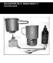
PROPER INSTALLATION OF MEMBRANE HOUSING MOUNTS<br />
1. DO NOT FULLY TIGHTEN SCREW;<br />
ALLOW ¼ INCH SPACE BETWEEN HEAD<br />
OF SCREW AND WASHER<br />
2. HOUSING MOUNT WITH MEMBRANE<br />
HOUSING IN PLACE.<br />
• HOLDS MEMBRANE HOUSING FIRMLY<br />
• ABSORBS PUMP VIBRATION<br />
27
Preventive Maintenance Package<br />
Part # 8012905<br />
Kits & Accessories<br />
An expanded cruise kit which includes all components of the Extended Cruise Kit, plus a Silt<br />
Reduction Kit. This kit is strongly recommended for extended cruising and variable water<br />
conditions.<br />
Silt Reduction Kit<br />
Part # 8012859<br />
This kit is intended to protect the high pressure pump and reverse osmosis membrane from<br />
excessive exposure to silt and other suspended particulates. It should be used in brackish<br />
water, shallow water, inland waterways, areas of glacial runoff and other similar situations. The<br />
Silt Reduction Kit includes a 5-micron prefilter which follows the standard 30-micron filter<br />
supplied with the watermaker. Also included is a 1-amp boost pump to ensure adequate intake<br />
flow to the watermaker.<br />
Extended Cruise Kit (Recommended)<br />
Part # 8012895<br />
Includes items needed for regular care and seasonal maintenance and/or storage. Contains (1)<br />
Repair Seal Kit, (1) container Acid Cleaner, (2) containers Alkaline Cleaner, (1) container of<br />
Membrane Preservative and (6) 30-micron prefilter elements.<br />
Repair Seal Kit (Recommended)<br />
Part # 8012889<br />
A set of all user-serviceable seals and parts for the high pressure pump. This kit also includes<br />
replacement gear oil for the drive assembly. A Repair Seal Kit should be installed after each<br />
approximately 1000 hours of use.<br />
Cleaning & Storage Chemicals<br />
Acid Cleaner (8 oz.) Part # 8013608 (1)<br />
Alkaline Cleaner (8 oz.) Part # 8013615 (1)<br />
Membrane Preservative (8 oz.) Part # 8013609 (1)<br />
Note: You may order parts and kits through our retailers or from <strong>Katadyn</strong>, Inc., directly at 800-<br />
755-6701. If ordering directly, be sure to include detailed shipping instructions as well as credit<br />
card information.<br />
QUESTIONS CALL 800-755-6701 or 763-746-3500<br />
28
Service Log<br />
Date<br />
Preserved<br />
M b<br />
Cleaned<br />
M b<br />
Other Service<br />
29
WARRANTY<br />
LIMITED WARRANTY FOR POWERSURVIVOR <strong>80E</strong> WATERMAKER<br />
THIS LIMITED WARRANTY AND THE REMEDY PROVIDED HEREIN ARE EXCLUSIVE AND<br />
IN LIEU OF ALL OTHER EXPRESS WARRANTIES AND, UNLESS STATED HEREIN, ANY<br />
STATEMENTS OR REPRESENTATIONS MADE BY OTHER PERSON OR FIRM ARE VOID.<br />
THE DURATION OF ANY IMPLIED WARRANTIES OF MERCHANTABILITY OR FITNESS<br />
FOR A PARTICULAR PURPOSE SHALL BE LIMITED TO THE DURATION OF THE<br />
EXPRESS LIMITED WARRANTY. NEITHER KATADYN NORTH AMERICA, INC. (KATADYN)<br />
NOR ITS AFFILIATES SHALL BE LIABLE FOR ANY INCIDENTAL, CONSEQUENTIAL OR<br />
SPECIAL LOSSES OR DAMAGES, RESULTING FROM THE USE OR INABILITY TO USE<br />
THE POWERSURVIVOR <strong>80E</strong> WATERMAKER, WHETHER RESULTING FROM BREACH OF<br />
WARRANTY OR ANY OTHER LEGAL THEORY.<br />
This Limited Warranty gives you specific legal rights, and you may also have other rights which<br />
vary from State to State. Some States do not allow limitations on how long an implied warranty<br />
lasts, or do not allow the exclusion or limitation of incidental or consequential damages, so the<br />
above limitations or exclusions may not apply to you.<br />
What Is Covered: KATADYN warrants to the original purchaser that the <strong>PowerSurvivor</strong> <strong>80E</strong><br />
Watermaker enclosed with this Limited Warranty conforms to the manufacturer’s specifications<br />
and is free from defects in workmanship and material for a period of three years from the date of<br />
original purchase. If the original purchaser transfers the <strong>PowerSurvivor</strong> <strong>80E</strong> Watermaker to<br />
another person, this Limited Warranty will not be enforceable by the person to whom the<br />
product is transferred.<br />
What We Will Do To Correct Problems: Should your <strong>PowerSurvivor</strong> <strong>80E</strong> Watermaker prove<br />
defective during this period, you must notify KATADYN at 6325 Sandburg Rd, Suite 400,<br />
Minneapolis, MN 55427, or an authorized distributor or dealer of KATADYN. You must permit<br />
KATADYN or its representatives to make such investigation, examination and tests as<br />
KATADYN deems appropriate and, if requested to do so, you will return the product to the<br />
factory at the address set forth above. KATADYN’s sole obligation under this Limited Warranty<br />
is, at its option, to repair or replace the defective unit, without charge for parts or labor. Postage,<br />
insurance or shipping costs incurred in presenting your <strong>PowerSurvivor</strong> <strong>80E</strong> Watermaker product<br />
for warranty service are your responsibility.<br />
What Is Not Covered: This Limited Warranty is contingent upon proper use and maintenance<br />
of the product; it does not cover products that have been improperly shipped or improperly<br />
installed, or that have been misused, abused, neglected, or improperly maintained, cleaned or<br />
stored, or that have been serviced other than by an authorized KATADYN distributor or dealer.<br />
The <strong>PowerSurvivor</strong> <strong>80E</strong> Watermaker can be damaged by oil, grease, chlorine and certain other<br />
organic or inorganic substances. It must be cleaned carefully after use, and requires periodic<br />
maintenance. Failure to observe the precautions listed in the User’s <strong>Manual</strong> may constitute<br />
improper use or maintenance of the product and causes this Limited Warranty not to apply. This<br />
Limited Warranty does not cover products from which the KATADYN label or logo or the rating<br />
label or serial number has been removed. This Warranty does not extend to normal wear or to<br />
replacement items, including but not limited to filter cartridges, pump seals and O-rings.<br />
31
<strong>Katadyn</strong> North America<br />
6325 Sandburg Road, Suite 400<br />
Minneapolis MN 55427, USA<br />
Phone: 800-755-6701<br />
Fax: 800-548-0406<br />
www.katadyn.com<br />
marine@katadyn.com<br />
<strong>Katadyn</strong> Products Inc.<br />
Birkenweg 4<br />
8304 Wallisellen<br />
Switzerland<br />
Phone: +41-1-839-2111<br />
Fax: +41-1-830-7942<br />
www.katadyn.ch<br />
info@katadyn.ch<br />
Print No: 8012864/4