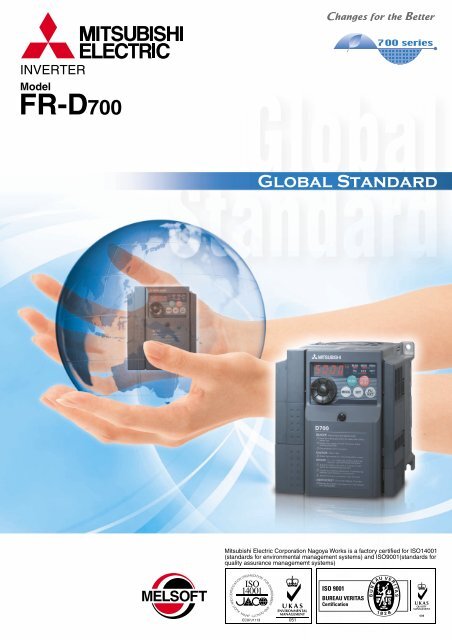
FR-D700 catalog - Mitsubishi Electric Automation (Thailand) Co., Ltd.
FR-D700 catalog - Mitsubishi Electric Automation (Thailand) Co., Ltd.
FR-D700 catalog - Mitsubishi Electric Automation (Thailand) Co., Ltd.

You also want an ePaper? Increase the reach of your titles
YUMPU automatically turns print PDFs into web optimized ePapers that Google loves.
• Features<br />
1<br />
High reliability is realized!<br />
Equipped with small class highest level of function/performance!!<br />
• Standard<br />
specifications<br />
5<br />
Safety stop function<br />
(1) (1)<br />
The <strong>FR</strong>-<strong>D700</strong> series is compliant to the EU<br />
Machinery Directive without the addition of<br />
previously required external devices.<br />
Operation of an external Emergency<br />
Stop device results in a highly reliable<br />
immediate shutoff of the <strong>D700</strong>'s output to<br />
the motor.<br />
This safety stop function conforms to the<br />
following standards.<br />
EN954-1 (ISO13849-1) Category 3<br />
IEC60204-1 Stop Category 0<br />
Provided by the user (present)<br />
Emergency stop<br />
For conventional model...<br />
Two MCs are necessary<br />
•High cost<br />
•Maintenance of two MCs is<br />
necessary<br />
•Installation space is necessary<br />
Safety function<br />
is equipped<br />
•Magnetic contactor (MC)<br />
•Emergency stop wiring<br />
<strong>FR</strong>-<strong>D700</strong><br />
Emergency stop<br />
Only one MC is enough<br />
with safety stop function!<br />
•<strong>Co</strong>st reduction<br />
•Maintenance of one MC<br />
•Installation space is reduced<br />
150%/1Hz high starting torque by general<br />
-purpose magnetic flux vector control<br />
General-purpose magnetic flux vector control and auto<br />
tuning function are available.<br />
It ensures operation that requires high starting torque,<br />
such as transfer machine including conveyer, hoist, lift,<br />
etc., washing machine, and agitators.<br />
•High torque 150%/1Hz and 200%/3Hz are realized<br />
•Auto tuning<br />
Many kinds of motors can be optimally controlled with<br />
<strong>Mitsubishi</strong> original "non-rotation " auto tuning function.<br />
(R1 constants tuning)<br />
(2)<br />
Brake resistor can be connected<br />
A brake transistor is built-in to the 0.4K or more.<br />
<strong>Co</strong>nnecting an optional brake resistor increases<br />
regeneration capability.<br />
It is useful for deceleration time reduction of a machine<br />
with a large inertia, such as fan, and operation of lift, etc.<br />
• Outline<br />
dimension<br />
drawings<br />
• Terminal connection<br />
diagram<br />
• Terminal specification<br />
explanation<br />
• Operation panel<br />
• Parameter unit<br />
• Parameter list<br />
7<br />
11<br />
13<br />
16<br />
(2)<br />
Spring clamp terminal (control circuit terminal)<br />
Highly reliable and easy wiring is realized by the incorporation of spring clamp terminals.*<br />
*: Main circuit terminal is screw terminal.<br />
Long-life design<br />
•The design life of the cooling fan has been extended to 10<br />
years *1 . The life of the fan can be further extended utilizing the<br />
it’s ON/OFF.<br />
•The longevity of the capacitors has been extended to 10<br />
years by the adoption of a capacitor with a specification of<br />
5000 hours and 105˚C surrounding air temperature *1,*2 .<br />
*1: Surrounding air temperature : annual average 40˚C (free from corrosive gas,<br />
flammable gas, oil mist, dust and dirt) Since the design life is a calculated value, it is<br />
not a guaranteed value.<br />
*2: Output current : 80% of the inverter rated current<br />
•Life indication of critical components<br />
<strong>Co</strong>mponents<br />
<strong>Co</strong>oling fan<br />
Main circuit smoothing capacitor<br />
Printed board smoothing capacitor<br />
• Easy wiring<br />
Wiring is completed only<br />
by inserting wires treated<br />
with bar terminal (max,<br />
diameter 1.5mm)<br />
Capable of wiring without<br />
a bar terminal.<br />
(3) (4)<br />
Guideline of the <strong>FR</strong>-<strong>D700</strong> Life<br />
10 years<br />
10 years<br />
10 years<br />
Guideline of JEMA *3<br />
2 to 3 years<br />
5 years<br />
5 years<br />
*3: Excerpts from "Periodic check of the transistorized inverter" of JEMA (Japan <strong>Electric</strong>al<br />
Manufacturerís Association)<br />
• High reliability<br />
Spring structure in terminal contact<br />
section inside prevents contact fault<br />
by vibration.<br />
• Maintenance is unnecessary<br />
Screw retightening is unnecessary.<br />
Most advanced life check<br />
•Degrees of deterioration of main circuit capacitor, control<br />
circuit capacitor, and inrush current limit circuit can be<br />
monitored.<br />
•Trouble can be avoided with the self-diagnostic alarm *4 that is<br />
output when the life span is near.<br />
Password function<br />
Registering 4-digit password can limit<br />
parameter read/write.<br />
It is effective for parameter setting<br />
protection.<br />
(example: hoist)<br />
(example: automobile production line)<br />
*4: If any one of main circuit capacitor, control circuit capacitor, inrush current restriction<br />
circuit or cooling fan reaches the output level, an alarm is output. Capacity of the main<br />
circuit capacitor can be measured by setting parameter at a stop and turning the<br />
power from off to on. Measuring the capacity enables alarm to be output.<br />
The cooling fan outputs alarm by using fan speed detection.<br />
(5)<br />
(3)<br />
(example: conveyer)<br />
Enhanced function<br />
(example:<br />
industrial washing machine)<br />
New functions and useful functions from superior models<br />
support all sorts of applications.<br />
• Regeneration avoidance function<br />
For a pressing machine and<br />
fan rotated faster than the set<br />
speed due to the effect of<br />
another fan, a trip can be<br />
made less likely to occur by<br />
automatically increasing<br />
frequency at regeneration.<br />
• Optimum excitation control<br />
This control enables the motor<br />
efficiency to its optimum. More<br />
energy saving is possible in<br />
applications with variable load<br />
torque characteristic such as<br />
fan and pump.<br />
(example: pressing machine)<br />
(example: air-conditioning fan)<br />
(example: pump)<br />
(example: automated storage)<br />
• Power failure-time deceleration-to-stop function<br />
The motor can be decelerated to a stop when a power<br />
failure or undervoltage occurred to prevent the motor<br />
from coasting.<br />
For fail-safe of machine tool, etc., it is effective to stop<br />
the motor when a power failure has occurred.<br />
• Dancer control<br />
Entering position detection signal of dancer roll to use<br />
PID control enables tension control by dancer roll.<br />
• Traverse function<br />
Traverse function for wind-up drum of spinning<br />
machine and wiredrawing machine prevents<br />
unevenness and deformation at thread winding.<br />
(example: textile machine)<br />
(example: spindle)<br />
(example: wiredrawing machine)<br />
• Protective<br />
functions<br />
• Option and<br />
peripheral devices<br />
• Precautions for<br />
operation/selection<br />
• Precautions for peripheral<br />
device selection<br />
1 2<br />
• <strong>FR</strong>-<strong>D700</strong> Series<br />
Specification<br />
Difference List<br />
• Warranty<br />
• International<br />
FA Center<br />
23<br />
24<br />
27<br />
32<br />
33
Quick setup with the setting dial<br />
Setting is easily done from a personal<br />
computer using the <strong>FR</strong> <strong>Co</strong>nfigurator<br />
(option) (available soon)<br />
<strong>Co</strong>nnecting a personal computer and the inverter via RS-485<br />
communication realizes setting with wizard (interactive) function<br />
of the <strong>FR</strong> <strong>Co</strong>nfigurator (inverter setup software).<br />
In addition, a parameter setting can be converted from the <strong>FR</strong>-<br />
S500 series to the <strong>FR</strong>-<strong>D700</strong> series by "convert" function.<br />
Displays monitor data in waveform. [Graph]<br />
Enclosure surface operation panel<br />
<strong>FR</strong>-PA07 (option)<br />
Optional enclosure surface operation panel (<strong>FR</strong>-PA07) can be<br />
connected. In addition, an operation panel for the <strong>FR</strong>-E500<br />
series can be connected.<br />
The operation panel of the inverter can not be removed.<br />
A parameter unit connection cable (<strong>FR</strong>-CB20 ) is<br />
separately necessary.<br />
Parameter unit <strong>FR</strong>-PU07 (option)<br />
An optional parameter unit (<strong>FR</strong>-PU07) can be connected as well.<br />
A parameter unit connection cable (<strong>FR</strong>-CB20<br />
) is separately necessary.<br />
Enhanced communication function<br />
(5)<br />
• Modbus and <strong>Mitsubishi</strong> inverter protocol<br />
Supports Modbus RTU<br />
<strong>Co</strong>mmunication speed of RS-485 has been improved<br />
(communication at 38.4kbps is available)<br />
"Multi command mode" has been added to <strong>Mitsubishi</strong> inverter protocol<br />
(data processing time of the inverter has been reduced to 1/4)<br />
Easy replacement of cooling fan<br />
(1) (1) (2)<br />
<strong>Mitsubishi</strong> inverter has a setting dial of course.<br />
•The scrolling speed of the dial was made to variable for more<br />
improved operability.<br />
•The nonslip setting dial is easier to turn.<br />
(2) (3)<br />
Setting wizard function (example: acceleration/deceleration time setting)<br />
Acceleration/deceleration<br />
pattern setting<br />
Parameter list display<br />
Acceleration/deceleration<br />
time setting<br />
(4)<br />
•Setting such as direct input method with a numeric<br />
keypad, operation status indication, and help<br />
function are usable.<br />
Eight languages can be displayed.<br />
•Parameter setting values of maximum of three<br />
inverters can be stored.<br />
•A battery pack type (<strong>FR</strong>-PU07BB(-L)) allows<br />
parameter setting and parameter copy without<br />
powering on the inverter. (available soon)<br />
•To use a parameter unit with battery pack (<strong>FR</strong>-PU07BB)<br />
outside Japan, order a “<strong>FR</strong>-PU07BB-L” (parameter unit type<br />
indicated on the package has L at the end).<br />
Since enclosed batteries may conflict with laws in countries to<br />
be used (new EU Directive on batteries and accumulators, etc.),<br />
batteries are not enclosed with an <strong>FR</strong>-PU07BB except Japan.<br />
A cooling fan is provided on top<br />
of the inverter of all capacities<br />
requiring a cooling fan (1.5K or<br />
more).<br />
A cooling fan can be easily<br />
replaced without disconnecting<br />
main circuit wires.<br />
(1)<br />
RoHS Directive compliant<br />
Human and environment-friendly inverter in compliant with<br />
RoHS Directive.<br />
RoHS Directive requires member nations must guarantee that new electrical and electronic<br />
equipment sold in the market after July 1, 2006 do not contain lead, cadmium, mercury,<br />
hexavalent chromium, polybrominated biphenyl (PBB) and polybrominated diphenyl ether<br />
(PBDE) flame retardants<br />
mark indicating RoHS Directive compliance is printed on the package.<br />
<strong>Co</strong>mbed shaped wiring cover<br />
Since a cover can be fitted<br />
after wiring, wiring work is<br />
easily done.<br />
The lineup of EMC filter integrated models.<br />
<strong>Co</strong>mplies with UL, cUL,EN (LVD) standards<br />
The lineup of three phase 200V/400V class goes to 15K.<br />
For the <strong>FR</strong>-<strong>D700</strong> series, North American (NA), EU (EC), and Chinese (CHT) specifications also are supported.<br />
*: This <strong>catalog</strong> explains based on the Japanese specifications.<br />
<strong>Co</strong>nsult our sales office for specifications of each country.<br />
Symbol<br />
1<br />
2<br />
4<br />
Voltage<br />
100V class<br />
200V class<br />
400V class<br />
<strong>FR</strong>-D740<br />
Symbol<br />
None<br />
S<br />
W<br />
Number of Power Phases<br />
Three-phase input<br />
Single-phase input<br />
Single-phase input<br />
(double voltage output)<br />
(3)<br />
(3)<br />
EMC filter integrated model<br />
(to be released)<br />
-0.4K-<br />
Symbol<br />
0.1K to 15K<br />
Inverter Capacity<br />
Indicate capacity<br />
"kW".<br />
Symbol<br />
None<br />
C<br />
Protective Structure<br />
Enclosed-type structure IP20<br />
Totally enclosed structure IP40<br />
Features<br />
Standard<br />
Specifications<br />
Outline<br />
Dimension<br />
Drawings<br />
Terminal <strong>Co</strong>nnection<br />
Diagram<br />
Terminal Specification<br />
Explanation<br />
Operation panel<br />
Parameter unit<br />
Parameter<br />
List<br />
Protective<br />
Functions<br />
Options<br />
Instructions<br />
<strong>FR</strong>-<strong>D700</strong> Series<br />
Specification<br />
Difference List<br />
Warranty<br />
International<br />
FA Center<br />
Easily replaceable compact body<br />
(1) (2)<br />
Installation size is the same as that of the <strong>FR</strong>-S500 series which<br />
is the smallest model of the <strong>Mitsubishi</strong> inverter.<br />
128mm<br />
Side by side installation saves space<br />
Space can be saved by side by side no clearance installation*.<br />
*: Use the inverter at the surrounding air temperature of 40˚C or less.<br />
Power<br />
Supply<br />
Three phase<br />
200V<br />
Three phase<br />
400V<br />
Single phase<br />
200V *<br />
Single phase<br />
100V *<br />
Inverter Type<br />
<strong>FR</strong>-D720-<br />
<strong>FR</strong>-D740-<br />
<strong>FR</strong>-D720S-<br />
<strong>FR</strong>-D710W-<br />
K<br />
K<br />
K<br />
K<br />
Inverter Capacity 0.1 0.2 0.4 0.75 1.5 2.2 3.7 5.5 7.5<br />
Enclosed structure (IP20)<br />
Totally-enclosed structure (IP40)<br />
Enclosed structure (IP20)<br />
Totally-enclosed structure (IP40)<br />
Enclosed structure (IP20)<br />
Enclosed structure (IP20)<br />
11 15<br />
*: Output of the single-phase 200V and single-phase 100V input models is three-phase 200V. :Available models :Models to be released :Not available<br />
<strong>FR</strong>-D740-0.4K<br />
<strong>FR</strong>-S540E-0.4K<br />
3 4
Standard specifications<br />
Rating<br />
• Three-phase 400V power supply<br />
Model <strong>FR</strong>-D740-K(-C)∗6 0.4 0.75 1.5 2.2 3.7 5.5 7.5<br />
Model <strong>FR</strong>-D740--NA 012 022 036 050 080 120 160<br />
Model <strong>FR</strong>-D740--EC 012 022 036 050 080 120 160<br />
Model <strong>FR</strong>-D740-K-CHT 0.4 0.75 1.5 2.2 3.7 5.5 7.5<br />
Applicable motor capacity (kW)∗1 0.4 0.75 1.5 2.2 3.7 5.5 7.5<br />
Rated capacity (kVA)∗2 1.2 2.0 3.0 4.6 7.2 9.1 13.0<br />
Power supply Output<br />
Rated current (A) 1.2 2.2 3.6 5.0 8.0 12.0 16.0<br />
Overload current rating∗3<br />
150% 60s, 200% 0.5s (inverse-time characteristics)<br />
Voltage∗4<br />
Three-phase 380 to 480V<br />
Rated input voltage/frequency<br />
Three-phase 380 to 480V 50Hz/60Hz<br />
Permissible AC voltage fluctuation<br />
325 to 528V 50Hz/60Hz<br />
Permissible frequency fluctuation ±5%<br />
Power supply capacity (kVA)∗5 1.5 2.5 4.5 5.5 9.5 12 17<br />
Protective structure (JEM1030)<br />
Enclosed type (IP20). IP40 for totally enclosed structure series.<br />
<strong>Co</strong>oling system Self-cooling Forced air cooling<br />
Approximate mass (kg) 1.2 1.2 1.3 1.4 1.5 3.1 3.1<br />
∗1 The applicable motor capacity indicated is the maximum capacity applicable for use of the <strong>Mitsubishi</strong> 4-pole standard motor.<br />
∗2 The rated output capacity indicated assumes that the output voltage is 440V.<br />
∗3 The % value of the overload current rating indicated is the ratio of the overload current to the inverter's rated output current. For repeated duty, allow time for<br />
the inverter and motor to return to or below the temperatures under 100% load.<br />
∗4 The maximum output voltage does not exceed the power supply voltage. The maximum output voltage can be changed within the setting range. However,<br />
∗5<br />
∗6<br />
the pulse voltage value of the inverter output side voltage remains unchanged at about 2 that of the power supply.<br />
The power supply capacity varies with the value of the power supply side inverter impedance (including those of the input reactor and cables).<br />
Totally enclosed structure series ends with -C.<br />
• Single-phase 200V power supply<br />
Model <strong>FR</strong>-D720S-K 0.1 0.2 0.4 0.75 1.5 2.2<br />
Model <strong>FR</strong>-D720S--NA 008 014 025 042 070 100<br />
Model <strong>FR</strong>-D720S--EC 008 014 025 042 070 100<br />
Model <strong>FR</strong>-D720S-K-CHT 0.1 0.2 0.4 0.75 1.5 2.2<br />
Applicable motor capacity (kW)∗1 0.1 0.2 0.4 0.75 1.5 2.2<br />
Rated capacity (kVA)∗2 0.3 0.5 1.0 1.6 2.8 3.8<br />
Power supply Output<br />
Rated current (A) 0.8 1.4 2.5 4.2 7.0 10.0<br />
Overload current rating∗3<br />
150% 60s, 200% 0.5s (inverse-time characteristics)<br />
Voltage∗4<br />
Three-phase 200 to 240V<br />
Rated input voltage/frequency<br />
Single-phase 200 to 240V 50Hz/60Hz<br />
Permissible AC voltage fluctuation<br />
170 to 264V 50Hz/60Hz<br />
Permissible frequency fluctuation ±5%<br />
Power supply capacity (kVA)∗5 0.5 0.9 1.5 2.3 4.0 5.2<br />
Protective structure (JEM1030)<br />
Enclosed type (IP20).<br />
<strong>Co</strong>oling system Self-cooling Forced air cooling<br />
Approximate mass (kg) 0.5 0.6 0.9 1.1 1.5 1.9<br />
∗1 The applicable motor capacity indicated is the maximum capacity applicable for use of the <strong>Mitsubishi</strong> 4-pole standard motor.<br />
∗2 The rated output capacity indicated assumes that the output voltage is 230V.<br />
∗3 The % value of the overload current rating indicated is the ratio of the overload current to the inverter's rated output current. For repeated duty, allow time for<br />
the inverter and motor to return to or below the temperatures under 100% load.<br />
∗4 The maximum output voltage does not exceed the power supply voltage. The maximum output voltage can be changed within the setting range. However,<br />
∗5<br />
the pulse voltage value of the inverter output side voltage remains unchanged at about 2 that of the power supply.<br />
The power supply capacity varies with the value of the power supply side inverter impedance (including those of the input reactor and cables).<br />
5
<strong>Co</strong>mmon specifications<br />
<strong>Co</strong>ntrol specifications<br />
Operation specifications<br />
Indication<br />
Soft-PWM control/high carrier frequency PWM control (V/F control, general-purpose magnetic flux vector control,<br />
<strong>Co</strong>ntrol method<br />
optimum excitation control can be selected)<br />
Output frequency range<br />
0.2 to 400Hz<br />
Frequency setting<br />
resolution<br />
Analog input<br />
0.06Hz/60Hz (terminal2, 4: 0 to 10V/10bit)<br />
0.12Hz/60Hz (terminal2, 4: 0 to 5V/9bit)<br />
0.06Hz/60Hz (terminal4: 0 to 20mA/10bit)<br />
Digital input 0.01Hz<br />
Frequency Analog input Within ±1% of the max. output frequency (25°C ±10°C)<br />
accuracy<br />
Digital input Within 0.01% of the set output frequency<br />
Base frequency can be set from 0 to 400Hz<br />
Voltage/frequency characteristics<br />
<strong>Co</strong>nstant torque/variable torque pattern can be selected<br />
Starting torque<br />
150% or more (at 1Hz)...when general-purpose magnetic flux vector control and slip compensation is set<br />
Torque boost<br />
Manual torque boost<br />
0.1 to 3600s (acceleration and deceleration can be set individually), linear or S-pattern acceleration/deceleration<br />
Acceleration/deceleration time setting<br />
mode can be selected.<br />
DC injection brake<br />
Operation frequency (0 to 120Hz), operation time (0 to 10s), operation voltage (0 to 30%) variable<br />
Stall prevention operation level Operation current level can be set (0 to 200% adjustable), whether to use the function or not can be selected<br />
Two points<br />
Frequency setting Analog input Terminal 2: 0 to 10V, 0 to 5V can be selected<br />
signal<br />
Terminal 4: 0 to 10V, 0 to 5V, 4 to 20mA can be selected<br />
Digital input Entered from operation panel and parameter unit. Frequency setting increments is selectable<br />
Start signal<br />
Forward and reverse rotation or start signal automatic self-holding input (3-wire input) can be selected.<br />
Five points<br />
You can select from among multi-speed selection, remote setting, second function selection, terminal 4 input<br />
selection, JOG operation selection, PID control valid terminal, external thermal input, PU-external operation<br />
Input signal<br />
switchover, V/F switchover, output stop, start self-holding selection, traverse function selectiom, forward rotation,<br />
reverse rotation command, inverter reset, PU-NET operation switchover, external-NET operation switchover,<br />
command source switchover, inverter operation enable signal, and PU operation external interlock<br />
Maximum/minimum frequency setting, frequency jump operation, external thermal relay input selection, automatic<br />
restart after instantaneous power failure operation, forward/reverse rotation prevention, remote setting, second<br />
Operational functions<br />
function, multi-speed operation, regeneration avoidance, slip compensation, operation mode selection, offline<br />
auto tuning function, PID control, computer link operation (RS-485), optimum excitation control, power failure<br />
stop, speed smoothing control, Modbus-RTU<br />
Output signal<br />
Output signal<br />
points<br />
Operating status<br />
For meter<br />
Output points<br />
For meter<br />
Operation panel<br />
Parameter unit<br />
(<strong>FR</strong>-PU07)<br />
Additional display<br />
by the parameter<br />
unit (<strong>FR</strong>-PU04/<strong>FR</strong>-<br />
PU07) only<br />
Protective/warning function<br />
Environment<br />
Open collector<br />
output<br />
Relay output<br />
Pulse output<br />
One point<br />
One point<br />
You can select from among inverter operation, up-to-frequency, overload alarm, output frequency detection,<br />
regenerative brake prealarm, electronic thermal relay function prealarm, inverter operation ready, output current<br />
detection, zero current detection, PID lower limit, PID upper limit, PID forward/reverse rotation output, fan<br />
alarm∗2, heatsink overheat pre-alarm, deceleration at an instantaneous power failure, PID control activated, PID<br />
output interruption, during retry, life alarm, current average value monitor, remote output, alarm output, fault<br />
output, fault output 3, and maintenance timer alarm<br />
MAX 2.4kHz: one point<br />
You can select from among output frequency, motor current (steady), output voltage, frequency setting, converter<br />
output voltage, regenerative brake duty, electronic thermal relay function load factor, output current peak value,<br />
converter output voltage peak value, reference voltage output, motor load factor, PID set point, PID measured<br />
value, output power, PID deviation, Motor thermal load factor, Inverter thermal load factor<br />
Pulse train output (1440 pulses/s/full scale)<br />
You can select from among output frequency, motor current (steady), output voltage, frequency setting,<br />
cumulative energization time, actual operation time, converter output voltage, regenerative brake duty, electronic<br />
Operating status thermal relay function load factor, output current peak value, converter output voltage peak value, motor load<br />
factor, PID set point, PID measured value, PID deviation, inverter I/O terminal monitor, output power, cumulative<br />
power, motor thermal load factor, inverter thermal load factor, PTC thermistor resistance.<br />
Fault definition is displayed when the fault occurs and the past 8 fault definitions (output voltage/current/<br />
Fault definition<br />
frequency/cumulative energization time right before the fault occurs) are stored<br />
Operating status Not used<br />
Fault definition Output voltage/current/frequency/cumulative energization time immediately before the fault occurs<br />
Interactive<br />
Function (help) for operation guide<br />
guidance<br />
<br />
Overcurrent during acceleration, overcurrent during constant speed, overcurrent during deceleration, overvoltage<br />
during acceleration, overvoltage during constant speed, overvoltage during deceleration, inverter protection<br />
thermal operation, motor protection thermal operation, heatsink overheat, input phase failure ∗4 ∗5, output side<br />
earth (ground) fault overcurrent at start∗4, output phase failure, external thermal relay operation ∗4, PTC<br />
thermistor operation∗4, parameter error, PU disconnection, retry count excess ∗4, CPU fault, brake transistor<br />
alarm, inrush resistance overheat, analog input error, stall prevention operation, output current detection value<br />
exceeded<br />
<br />
Fan alarm∗2, overcurrent stall prevention, overvoltage stall prevention, PU stop, parameter write error,<br />
regenerative brake prealarm ∗4, electronic thermal relay function prealarm, maintenance output ∗4, undervoltage,<br />
operation panel lock, password locked, inverter reset<br />
-10°C to +50°C (non-freezing) (-10°C to +40°C for totally-enclosed structure feature) ∗3<br />
90%RH maximum (non-condensing)<br />
-20°C to +65°C<br />
Indoors (without corrosive gas, flammable gas, oil mist, dust and dirt etc.)<br />
Maximum 1000m above sea level, 5.9m/s 2 or less<br />
Surrounding air temperature<br />
Ambient humidity<br />
Storage temperature∗1<br />
Atmosphere<br />
Altitude/vibration<br />
∗1 Temperatures applicable for a short time, e.g. in transit.<br />
∗2 As the 0.75K or less is not provided with the cooling fan, this alarm does not function.<br />
∗3 When using the inverters at the surrounding air temperature of 40°C or less, the inverters can be installed closely attached (0cm clearance).<br />
∗4 This protective function does not function in the initial status.<br />
∗5 This protective function is available with the three-phase power input specification model only.<br />
Features<br />
Standard<br />
Specifications<br />
Outline<br />
Dimension<br />
Drawings<br />
Terminal <strong>Co</strong>nnection<br />
Diagram<br />
Terminal Specification<br />
Explanation<br />
Operation panel<br />
Parameter unit<br />
Parameter<br />
List<br />
Protective<br />
Functions<br />
Options<br />
Instructions<br />
<strong>FR</strong>-<strong>D700</strong> Series<br />
Specification<br />
Difference List<br />
Warranty<br />
International<br />
FA Center<br />
6
Outline Dimension Drawings<br />
•<strong>FR</strong>-D720S-0.1K to 0.75K<br />
1-φ5 hole<br />
5<br />
56<br />
68<br />
5 118 5<br />
128<br />
Rating<br />
plate<br />
D<br />
4<br />
D1<br />
Inverter Type D D1<br />
<strong>FR</strong>-D720S-0.1K, 0.2K 80.5 10<br />
<strong>FR</strong>-D720S-0.4K 142.5 42<br />
<strong>FR</strong>-D720S-0.75K 162.5 62<br />
(Unit: mm)<br />
•<strong>FR</strong>-D740-0.4K to 3.7K<br />
•<strong>FR</strong>-D720S-1.5K<br />
2-φ5 hole<br />
5<br />
5 118<br />
5<br />
128<br />
Rating<br />
plate<br />
FAN *<br />
5<br />
96<br />
D1<br />
108<br />
D<br />
∗<br />
<strong>FR</strong>-D740-0.4K, 0.75K are not provided with the cooling fan.<br />
Inverter Type D D1<br />
<strong>FR</strong>-D740-0.4K, 0.75K 129.5 54<br />
<strong>FR</strong>-D740-1.5K 135.5<br />
<strong>FR</strong>-D740-2.2K 155.5<br />
<strong>FR</strong>-D740-3.7K 165.5<br />
60<br />
<strong>FR</strong>-D720S-1.5K 155.5<br />
(Unit: mm)<br />
7
•<strong>FR</strong>-D720S-2.2K<br />
2-φ5 hole<br />
138 6<br />
150<br />
FAN<br />
Features<br />
Standard<br />
Specifications<br />
Rating<br />
plate<br />
Outline<br />
Dimension<br />
Drawings<br />
5<br />
128<br />
140<br />
6<br />
145<br />
60<br />
5<br />
Terminal <strong>Co</strong>nnection<br />
Diagram<br />
Terminal Specification<br />
Explanation<br />
Protective<br />
Functions<br />
Parameter<br />
List<br />
Operation panel<br />
Parameter unit<br />
(Unit: mm)<br />
•<strong>FR</strong>-D740-5.5K, 7.5K<br />
6<br />
Options<br />
2-φ5 hole<br />
FAN<br />
Instructions<br />
138<br />
150<br />
Rating<br />
plate<br />
<strong>FR</strong>-<strong>D700</strong> Series<br />
Specification<br />
Difference List<br />
5<br />
208<br />
6<br />
10<br />
68<br />
Warranty<br />
International<br />
FA Center<br />
220<br />
155<br />
(Unit: mm)<br />
8
•Parameter unit (option) (<strong>FR</strong>-PU07)<br />
<br />
<br />
25.05<br />
83<br />
(14.2)<br />
(11.45)<br />
2.5<br />
40<br />
40<br />
*1<br />
*1<br />
135<br />
*1<br />
*1<br />
50<br />
67 51<br />
56.8<br />
Air-bleeding<br />
hole<br />
57.8<br />
4-R1<br />
26.5<br />
26.5 4-φ4 hole<br />
(Effective depth of the<br />
installation screw hole 5.0)<br />
M3 screw *2<br />
80.3<br />
∗1 When installing the <strong>FR</strong>-PU07 on the enclosure, etc., remove screws or fix the screws to the <strong>FR</strong>-PU07 with M3 nuts.<br />
∗2 Select the installation screw whose length will not exceed the effective depth of the installation screw hole. (Unit: mm)<br />
•Parameter unit (option) (<strong>FR</strong>-PU07BB (-L))<br />
<br />
83<br />
18<br />
8.2 46.7<br />
46.7<br />
135<br />
6<br />
44.7<br />
∗ Select the installation screw whose length will not exceed the effective depth of the installation screw hole.<br />
(Unit: mm)<br />
9
•Parameter unit (option) (<strong>FR</strong>-PU04)<br />
<br />
72 15 10.5<br />
125<br />
21.5<br />
80<br />
<br />
5-M3 screw<br />
Effective<br />
depth of the<br />
installation<br />
screw hole 4.5<br />
40<br />
40<br />
Select the installation screws whose length will not exceed the effective depth of the installation screw hole.<br />
48<br />
24<br />
13<br />
18.5<br />
14.5<br />
20<br />
17<br />
16.5<br />
11.75<br />
23.75<br />
5-φ4 hole<br />
Features<br />
Standard<br />
Specifications<br />
Outline<br />
Dimension<br />
Drawings<br />
Options<br />
Terminal <strong>Co</strong>nnection<br />
Diagram<br />
Terminal Specification<br />
Explanation<br />
•Enclosure surface operation panel (option) (<strong>FR</strong>-PA07)<br />
<br />
<br />
Warranty<br />
International<br />
FA Center<br />
Operation panel<br />
Parameter unit<br />
Parameter<br />
List<br />
Protective<br />
Functions<br />
<strong>FR</strong>-<strong>D700</strong> Series<br />
Specification<br />
Difference List<br />
Instructions<br />
81.5<br />
1.5<br />
13<br />
1.25<br />
1.5<br />
(Unit: mm)<br />
68<br />
22<br />
22<br />
59<br />
2-M3 screw<br />
(Unit: mm)<br />
10
Terminal <strong>Co</strong>nnection Diagram<br />
Source logic<br />
Main circuit terminal<br />
<strong>Co</strong>ntrol circuit terminal<br />
*1. DC reactor (<strong>FR</strong>-HEL)<br />
When connecting a DC reactor, remove the<br />
jumper across P1-P/+<br />
Single-phase power input<br />
MCCB MC<br />
Single-phase<br />
AC power<br />
supply<br />
Three-phase<br />
AC power<br />
supply<br />
MCCB<br />
MC<br />
R/L1<br />
S/L2<br />
Earth<br />
(Ground)<br />
Jumper<br />
R/L1<br />
S/L2<br />
T/L3<br />
P1<br />
*1<br />
P/+<br />
PR<br />
*7<br />
R<br />
*6<br />
N/-<br />
Brake unit<br />
(Option)<br />
U<br />
V<br />
W<br />
*6 A brake transistor is not built-in to the<br />
<strong>FR</strong>-D720S-0.1K and 0.2K.<br />
*7 Brake resistor (<strong>FR</strong>-ABR, MRS)<br />
Install a thermal relay to prevent an<br />
overheat and burnout of the brake resistor.<br />
(The brake resistor can not be connected<br />
to the <strong>FR</strong>-D720S-0.1K and 0.2K.)<br />
Motor<br />
IM<br />
Earth<br />
(Ground)<br />
Main circuit<br />
<strong>Co</strong>ntrol circuit<br />
Earth (Ground)<br />
<strong>Co</strong>ntrol input signals (No voltage input allowed)<br />
Forward<br />
Terminal functions vary rotation start<br />
with the input terminal<br />
Reverse<br />
assignment (Pr. 178 to rotation start<br />
Pr. 182)<br />
High<br />
speed<br />
Multi-speed selection<br />
*2 When using terminals PC-<br />
SD as a 24VDC power<br />
supply, take care not to<br />
short across terminals<br />
PC-SD.<br />
Middle<br />
speed<br />
Low<br />
speed<br />
<strong>Co</strong>ntact input common<br />
24VDC power supply<br />
<strong>Co</strong>ntact input common<br />
(<strong>Co</strong>mmon for external power supply transistor)<br />
STF<br />
STR<br />
RH<br />
RM<br />
RL<br />
SD<br />
PC *2<br />
SOURCE<br />
SINK<br />
C<br />
B<br />
A<br />
RUN<br />
SE<br />
Relay output<br />
(Fault output)<br />
Running<br />
Relay output<br />
Terminal functions vary<br />
by Pr. 192 A,B,C terminal<br />
function selection<br />
Open collector output<br />
Terminal functions vary by<br />
Pr. 190 RUN terminal function<br />
selection<br />
Open collector output common<br />
Sink/source common<br />
Frequency setting signals (Analog)<br />
3<br />
*3 Terminal input specifications Frequency<br />
can be changed by analog setting<br />
input specifications<br />
switchover (Pr. 73). potentiometer<br />
Terminal 10 and terminal 2 1/2W1kΩ<br />
are used as PTC input *5<br />
terminal (Pr. 561).<br />
1<br />
*4 Terminal input<br />
specifications can be<br />
changed by analog input<br />
specifications switchover<br />
(Pr. 267). Set the<br />
voltage/current input<br />
switch in the "V" position<br />
to select voltage input (0<br />
to 5V/0 to10V) and "I"<br />
(initial value) to select<br />
current input (4 to 20mA).<br />
Terminal 4<br />
input (+)<br />
(Current (-)<br />
input)<br />
2<br />
10(+5V)<br />
2 0 to 5VDC *3<br />
(0 to 10VDC)<br />
5(Analog common)<br />
4 4 to 20mADC<br />
0 to 5VDC<br />
0 to 10VDC<br />
*4<br />
V I<br />
Voltage/current<br />
input switch *4<br />
PU<br />
connector<br />
FM<br />
SD<br />
Calibration resistor<br />
*8<br />
+ -<br />
Indicator<br />
(Frequency meter, etc.)<br />
Moving-coil type<br />
1mA full-scale<br />
*8 It is not necessary when<br />
calibrating the indicator<br />
from the operation panel.<br />
*5 It is recommended to use 2W1kΩ<br />
when the frequency setting signal<br />
is changed frequently.<br />
Note<br />
• To prevent a malfunction caused by noise, separate the signal cables more than 10cm from the power cables.<br />
• After wiring, wire offcuts must not be left in the inverter.<br />
Wire offcuts can cause an alarm, failure or malfunction. Always keep the inverter clean. When drilling mounting holes<br />
in an enclosure etc., take care not to allow chips and other foreign matter to enter the inverter.<br />
• To ensure safety, for single-phase power input specification model, connect the power input to the inverter via a<br />
magnetic contactor and earth leakage circuit breaker or moulded case circuit breaker, and use the magnetic<br />
contactor to switch power on-off.<br />
• The output of the single-phase power input specification is three-phase 200V.<br />
11
Terminal Specification Explanation<br />
Type<br />
<strong>Co</strong>ntrol circuit/input signal<br />
Main circuit<br />
Frequency setting<br />
<strong>Co</strong>ntact input<br />
Terminal<br />
Symbol<br />
R/L1, S/L2,<br />
T/L3 ∗<br />
Terminal Name<br />
AC power input<br />
Description<br />
<strong>Co</strong>nnect to the commercial power supply. Keep these terminals open when using the high power<br />
factor converter (<strong>FR</strong>-HC) or power regeneration common converter (<strong>FR</strong>-CV).<br />
∗ When using single-phase power input, terminals are R/L1 and S/L2.<br />
U, V, W Inverter output <strong>Co</strong>nnect a three-phase squirrel-cage motor.<br />
P/+, PR<br />
Brake resistor <strong>Co</strong>nnect a brake transistor (MRS, <strong>FR</strong>-ABR) across terminals P/+-PR.<br />
connection (The brake resistor can not be connected to the <strong>FR</strong>-D720S-0.1K and 0.2K)<br />
P/+, N/- Brake unit connection<br />
P/+, P1 DC reactor connection Remove the jumper across terminals P/+-P1 and connect a DC reactor.<br />
Earth (Ground)<br />
External transistor<br />
common (source)<br />
24VDC power supply<br />
<strong>Co</strong>nnect the brake unit (<strong>FR</strong>-BU2), power regeneration common converter (<strong>FR</strong>-CV) or high power<br />
factor converter (<strong>FR</strong>-HC).<br />
For earthing (grounding) the inverter chassis. Must be earthed (grounded).<br />
STF Forward rotation start Turn on the STF signal to start forward rotation and turn it off to stop. When the STF and STR signals<br />
STR Reverse rotation start Turn on the STR signal to start reverse rotation and turn it off to stop.<br />
are turned on simultaneously,<br />
the stop command is given.<br />
RH, RM, RL Multi-speed selection Multi-speed can be selected according to the combination of RH, RM and RL signals.<br />
<strong>Co</strong>ntact input common<br />
(sink) (initial setting)<br />
<strong>Co</strong>mmon terminal for contact input terminal (sink logic) and terminal FM.<br />
When connecting the transistor output (open collector output), such as a programmable controller,<br />
SD<br />
when source logic is selected, connect the external power supply common for transistor output to this<br />
terminal to prevent a malfunction caused by undesirable currents.<br />
PC<br />
10<br />
2<br />
4<br />
5<br />
common<br />
External transistor<br />
common<br />
(sink) (initial setting)<br />
<strong>Co</strong>mmon output terminal for 24VDC 0.1A power supply (PC terminal).<br />
Isolated from terminals 5 and SE.<br />
When connecting the transistor output (open collector output), such as a programmable controller,<br />
when sink logic is selected, connect the external power supply common for transistor output to this<br />
terminal to prevent a malfunction caused by undesirable currents.<br />
<strong>Co</strong>ntact input common<br />
<strong>Co</strong>mmon terminal for contact input terminal (source logic).<br />
(source)<br />
24VDC power supply Can be used as 24VDC 0.1A power supply.<br />
Frequency setting<br />
power supply<br />
Frequency setting<br />
(voltage)<br />
Frequency setting<br />
(current)<br />
Frequency setting<br />
common<br />
Used as power supply when connecting potentiometer for frequency setting<br />
(speed setting) from outside of the inverter.<br />
Inputting 0 to 5VDC (or 0 to 10V) provides the maximum output<br />
frequency at 5V (10V) and makes input and output proportional.<br />
Use Pr. 73 to switch between input 0 to 5VDC (initial setting) and 0<br />
to 10VDC input.<br />
Inputting 0 to 20mADC (or 0 to 5V / 0 to 10V) provides the<br />
maximum output frequency at 20mA makes input and output<br />
proportional. This input signal is valid only when the AU signal is on<br />
(terminal 2 input is invalid). Use Pr. 267 to switch from among input<br />
4 to 20mA (initial setting), 0 to 5VDC and 0 to 10VDC. Set the<br />
voltage/current input switch in the "V" position to select voltage<br />
input (0 to 5V/0 to 10V).<br />
5VDC<br />
permissible load<br />
current 10mA<br />
Input resistance 10kΩ ± 1kΩ<br />
Permissible maximum voltage<br />
20VDC<br />
Voltage input:<br />
Input resistance 10kΩ ± 1kΩ<br />
Permissible maximum voltage<br />
20VDC<br />
Current input:<br />
Input resistance 233Ω ± 5Ω<br />
Maximum permissible current 30mA.<br />
<strong>Co</strong>mmon terminal for the frequency setting signals (terminals 2 or 4). Do not earth (ground).<br />
Features<br />
Standard<br />
Specifications<br />
Outline<br />
Dimension<br />
Drawings<br />
Terminal <strong>Co</strong>nnection<br />
Diagram<br />
Terminal Specification<br />
Explanation<br />
Operation panel<br />
Parameter unit<br />
Parameter<br />
List<br />
Protective<br />
Functions<br />
Options<br />
PTC<br />
thermistor<br />
<strong>Co</strong>ntrol circuit/output signal<br />
Pulse Open collector Relay<br />
10<br />
2<br />
A, B, C<br />
RUN<br />
SE<br />
FM<br />
PTC thermistor input<br />
Relay output<br />
(fault output)<br />
Inverter running<br />
Open collector<br />
output common<br />
For meter<br />
For connecting PTC thermistor output.<br />
When PTC thermistor protection is valid (Pr. 561 ≠ "9999"), terminal<br />
2 is not available for frequency setting.<br />
Adaptive PTC thermistor<br />
resistance:<br />
100Ω to 30kΩ<br />
1 changeover contact output indicates that the inverter fault occurs.<br />
Fault: discontinuity across B-C (continuity across A-C), Normal: continuity across B-C (discontinuity<br />
across A-C) <strong>Co</strong>ntact capacity 230VAC 0.3A (power factor = 0.4) 30VDC 0.3A<br />
Switched low when the inverter output frequency is equal to or<br />
Permissible load 24VDC<br />
higher than the starting frequency (initial value 0.5Hz). Switched<br />
(Maximum 27VDC) 0.1A<br />
high during stop or DC injection brake operation.<br />
(a voltage drop is 3.4V maximum<br />
(Low indicates that the open collector output transistor is on<br />
when the signal is on)<br />
(conducts). High indicates that the transistor is off (does not conduct))<br />
<strong>Co</strong>mmon terminal of terminal RUN and FU.<br />
Select one e.g. output frequency from monitor items. (Not output<br />
during inverter reset.) The output signal is proportional to the<br />
magnitude of the corresponding monitoring item.<br />
Permissible load current 1mA<br />
1440 pulses/s at 60Hz<br />
Instructions<br />
<strong>FR</strong>-<strong>D700</strong> Series<br />
Specification<br />
Difference List<br />
Warranty<br />
International<br />
FA Center<br />
<strong>Co</strong>mmunication<br />
— PU connector<br />
With the PU connector, RS-485 communication can be made.<br />
· <strong>Co</strong>nforming standard: EIA-485 (RS-485)<br />
· Transmission format: Multi-drop link<br />
· <strong>Co</strong>mmunication speed: 4800 to 38400bps<br />
· Overall extension: 500m<br />
Terminal for inverter<br />
manufacturer setting<br />
S1<br />
S2<br />
SO<br />
SC<br />
Keep these open. Otherwise, the inverter may be damaged.<br />
Do not remove wires for shorting across terminal S1 and SC, across terminal S2 and SC. If one of these wires is removed, the<br />
inverter cannot be operated.<br />
Note<br />
• Set Pr. 267 and a voltage/current input switch correctly, then input an analog signal in accordance with the setting. Applying<br />
a voltage with voltage/current input switch in "I" position (current input is selected) or a current with switch in "V" position<br />
(voltage input is selected) could cause component damage of the inverter or analog circuit of output devices.<br />
• The inverter will be damaged if power is applied to the inverter output terminals (U, V, W). Never perform such wiring.<br />
• indicates that terminal functions can be selected using Pr. 178 to Pr. 182, Pr. 190, Pr. 192 (I/O terminal function selection).<br />
• Terminal names and terminal functions are those of the factory set.<br />
12
Explanation of the Operation Panel<br />
The operation panel cannot be removed from the inverter.<br />
Operation mode indication<br />
PU: Lit to indicate PU operation mode.<br />
EXT: Lit to indicate external operation<br />
mode.<br />
NET: Lit to indicate network operation<br />
mode.<br />
PU, EXT: Lit to indicate external/PU<br />
combined operation mode 1, 2.<br />
Unit indication<br />
Hz: Lit to indicate frequency.<br />
(Flickers when the set frequency<br />
monitor is displayed.)<br />
A: Lit to indicate current.<br />
(Both "Hz" and "A" turn off when other<br />
than the above is displayed.)<br />
Monitor (4-digit LED)<br />
Shows the frequency, parameter number,<br />
etc.<br />
Setting dial<br />
(Setting dial: <strong>Mitsubishi</strong> inverter dial)<br />
Used to change the frequency setting<br />
and parameter values.<br />
Press to display the following.<br />
• Displays the set frequency in the<br />
monitor mode<br />
• Currently set value is displayed during<br />
calibration<br />
• Displays the order in the faults history<br />
mode<br />
Mode switchover<br />
Used to change each setting mode.<br />
Pressing simultaneously changes<br />
the operation mode.<br />
Pressing for a while (2s) can lock<br />
operation.<br />
Determination of each setting<br />
If pressed during operation, monitor<br />
changes as below;<br />
Running frequency<br />
Operating status display<br />
Lit or flicker during inverter operation. ∗<br />
∗ On: Indicates that forward rotation<br />
operation is being performed.<br />
Slow flickering (1.4s cycle):<br />
Reverse rotation operation<br />
Fast flickering (0.2s cycle):<br />
When was pressed or the start<br />
command was given, but the operation<br />
can not be made.<br />
• When the frequency command is less<br />
than the starting frequency.<br />
• When the MRS signal is input.<br />
Parameter setting mode<br />
Lit to indicate parameter setting mode.<br />
Monitor indication<br />
Lit to indicate monitoring mode.<br />
Stop operation<br />
Used to stop Run command.<br />
Fault can be reset when protective<br />
function is activated (fault).<br />
Operation mode switchover<br />
Used to switch between the PU and<br />
external operation mode.<br />
When using the external operation mode<br />
(operation using a separately connected<br />
frequency setting potentiometer and start<br />
signal), press this key to light up the EXT<br />
indication.<br />
(Press simultanesouly (0.5s) or<br />
change Pr. 79 setting to change to combined<br />
mode .)<br />
PU: PU operation mode<br />
EXT: External operation mode<br />
Cancels PU stop also.<br />
Start command<br />
The rotation direction can be selected by<br />
setting Pr. 40.<br />
Output current<br />
Output voltage<br />
13
Basic operation of the operation panel<br />
Operation mode switchover<br />
At powering on (external operation mode)<br />
Features<br />
Standard<br />
Specifications<br />
PU Jog operation mode<br />
Outline<br />
Dimension<br />
Drawings<br />
Faults history Parameter setting<br />
Monitor/frequency setting<br />
PU operation mode<br />
(output frequency monitor)<br />
Parameter setting mode<br />
Parameter clear<br />
Value change<br />
Output current monitor<br />
Value change<br />
STOP<br />
All parameter<br />
clear<br />
[Operation for displaying faults history]<br />
Past eight faults can be displayed.<br />
(The latest fault is ended by ".".)<br />
When no fault history exists,<br />
is displayed.<br />
Output voltage monitor<br />
Display the<br />
current setting<br />
Parameter and a setting value<br />
flicker alternately.<br />
Parameter write is completed!!<br />
Initial value<br />
change list<br />
(Example)<br />
and frequency flicker.<br />
Frequency setting has been<br />
written and completed!!<br />
(Example)<br />
Faults history clear<br />
Terminal <strong>Co</strong>nnection<br />
Diagram<br />
Terminal Specification<br />
Explanation<br />
Operation panel<br />
Parameter unit<br />
Parameter<br />
List<br />
Protective<br />
Functions<br />
Options<br />
Instructions<br />
<strong>FR</strong>-<strong>D700</strong> Series<br />
Specification<br />
Difference List<br />
Warranty<br />
International<br />
FA Center<br />
14
Explanations of Parameter unit<br />
Parameter unit (<strong>FR</strong>-PU07), parameter unit with battery pack (<strong>FR</strong>-PU07BB(-L) (available soon))<br />
• The parameter unit is a convenient tool for inverter setting<br />
such as direct input method with a numeric keypad,<br />
operation status indication, and help function.<br />
Eight languages can be displayed.<br />
• Parameter setting values of maximum of three inverters can<br />
be stored.<br />
• With the <strong>FR</strong>-PU07BB(-L), parameter check and setting<br />
change can be made without connecting a power supply to the<br />
inverter. Use AA nickel hydride batteries, AA alkali batteries, or<br />
AC adapter separately available as power supply.<br />
• To use a parameter unit with battery pack (<strong>FR</strong>-PU07BB)<br />
outside Japan, order a "<strong>FR</strong>-PU07BB-L" (parameter unit type<br />
indicated on the package has L at the end). Since enclosed<br />
batteries may conflict with laws in countries to be used (new<br />
EU Directive on batteries and accumulators, etc.), batteries<br />
are not enclosed with an <strong>FR</strong>-PU07BB except Japan.<br />
• Since the shape is specially designed for portable use, it is<br />
easy to work with the <strong>FR</strong>-PU07BB(-L) in hand.<br />
• The parameter unit connection cable <strong>FR</strong>-CB20 is required<br />
for connecting to the inverter.<br />
POWER lamp<br />
Lit when the power turns on.<br />
Monitor<br />
Liquid crystal display<br />
(16 characters 4 lines with backlight)<br />
Interactive parameter setting<br />
Trouble shooting guidance<br />
Monitor (frequency, current, power, etc.)<br />
<strong>FR</strong>-PU07<br />
ALARM lamp<br />
Lit to indicate an inverter alarm<br />
occurrence.<br />
Operation keys<br />
(Refer to the table on the right)<br />
<strong>FR</strong>-PU07BB(-L)<br />
Key<br />
to<br />
Description<br />
Use for parameter setting<br />
Press to choose the parameter setting mode.<br />
First priority monitor is displayed.<br />
In the initial setting, the output frequency is displayed.<br />
Operation cancel key<br />
Used to display the function menu.<br />
A variety of functions can be used on the function menu.<br />
Used to shift to the next item in the setting or monitoring mode.<br />
Used to enter a frequency, parameter number or set value.<br />
Inverter operates in the external operation mode.<br />
Used to select the PU operation mode to display the frequency<br />
setting screen.<br />
• Used to keep on increasing or decreasing the running<br />
frequency. Hold down to vary the frequency.<br />
• Press either of these keys on the parameter setting mode<br />
screen to change the parameter setting value sequentially.<br />
• On the selecting screen, these keys are used to move the cursor.<br />
• Hold down and press either of these keys to advance<br />
or return the display screen one page.<br />
Forward rotation command key.<br />
Reverse rotation command key.<br />
• Stop command key.<br />
• Used to reset the inverter when an alarm occurs.<br />
• Used to write a set value in the setting mode.<br />
• Used as a clear key in the all parameter clear or alarm history<br />
clear mode.<br />
• Used as a decimal point when entering numerical value.<br />
• Used as a parameter number read key in the setting mode.<br />
• Used as an item select key on the menu screen such as<br />
parameter list or monitoring list.<br />
• Used as an alarm definition display key in the alarm history<br />
display mode.<br />
• Used as a command voltage read key in the calibration mode.<br />
•Monitor: Merely pressing<br />
calls 6 different monitor screens in sequence.<br />
•Parameter setting: When changing 5s to 180s as the Pr. 8 Deceleration time setting<br />
•Pr. List:<br />
Switch power<br />
on or press<br />
•Multiple copies:<br />
READ:List<br />
0.00 Hz<br />
--- STOP EXT<br />
READ:List<br />
0.00 A<br />
--- STOP EXT<br />
READ:List<br />
0.0 V<br />
--- STOP EXT<br />
ALARM HISTORY<br />
Output frequency monitor Output current monitor Output voltage monitor Alarm history<br />
monitor<br />
Freq Set<br />
SET 0.00Hz<br />
0~400Hz<br />
SETTING MODE<br />
0~9:Set Pr.NO.<br />
Select Oper<br />
SETTING MODE<br />
Pr.NO.<br />
8<br />
<br />
8 Dec.T1<br />
5.0S<br />
0~3600<br />
OTHERS<br />
0.00Hz<br />
0.00A<br />
<br />
0.0V<br />
--- STOP EXT<br />
Selective monitor 3-step monitor<br />
(Running speed, motor torque, etc.<br />
from 16 different monitors)<br />
Displays the parameters list.<br />
You can select the parameter from the list to read and write the parameter setting.<br />
1 MONITOR<br />
2 PU Oper<br />
3 Pr.List<br />
4 Pr.Clear<br />
1 MONITOR<br />
2 PU Oper<br />
3 Pr.List<br />
4 Pr.Clear<br />
Using , move the<br />
cursor to "3 Pr. List".<br />
1 Setting Mode<br />
2 Pr.List<br />
3 Set Pr.List<br />
4 Def.Pr.List<br />
<br />
1 Setting Mode<br />
2 Pr.List<br />
3 Set Pr.List<br />
4 Def.Pr.List<br />
Using , move the<br />
cursor to "2 Pr. List".<br />
8 Dec.T1<br />
5.0S<br />
180S<br />
0~3600<br />
0 Trq Bst1<br />
1 Max.F1<br />
2 Min.F1<br />
3 VFbaseF1<br />
8 Dec.T1<br />
180.0S<br />
<strong>Co</strong>mpleted<br />
0 Trq Bst1<br />
6.0%<br />
Top two monitor types of<br />
the first priority monitor,<br />
output frequency, output<br />
current and output voltage<br />
are displayed in line<br />
9 Set THM<br />
2.55A<br />
You can read the parameter settings of the inverter into the <strong>FR</strong>-PU07 and store the settings of maximum<br />
three inverters. You can also copy the stored parameter settings to another inverter of the same series.<br />
1 MONITOR<br />
9 S/W<br />
2 PU Oper<br />
10 Selectop<br />
3 Pr.List<br />
11 Option<br />
4 Pr.Clear 12 PRCpy set<br />
Select "12 PRCpy set".<br />
1 <strong>Co</strong>py area 1<br />
2 <strong>Co</strong>py area 2<br />
3 <strong>Co</strong>py area 3<br />
Select the copy area.<br />
Select the "READ".<br />
<strong>Co</strong>py area 1<br />
1 Read VFD<br />
2 Write VFD<br />
3 Verifing<br />
Read "1 Read VFD".<br />
Select the "WRITE".<br />
<strong>Co</strong>py area 1<br />
1 Read VFD<br />
2 Write VFD<br />
3 Verifing<br />
Select "2 Write VFD".<br />
Select the "Verifying".<br />
<strong>Co</strong>py area 1<br />
1 Read VFD<br />
2 Write VFD<br />
3 Verifing<br />
Select "3 Verifing".<br />
Name:012<br />
:Select Char<br />
READ:Decide Char<br />
WRITE:DecideName<br />
Give a name.<br />
012<br />
Area 1 to VFD<br />
WRITE:Executing<br />
ESC:Cancel<br />
012<br />
Verify Area 1<br />
WRITE:Executing<br />
ESC:Cancel<br />
0~500<br />
0~30<br />
Parameter setting mode<br />
012<br />
Overwrite area 1<br />
WRITE:Executing<br />
ESC:Cancel<br />
Write.<br />
Param <strong>Co</strong>py<br />
Writing<br />
<strong>Co</strong>mpleted<br />
Please Reset<br />
Param <strong>Co</strong>py<br />
Verifying<br />
Please Wait<br />
Param <strong>Co</strong>py<br />
Reading<br />
<strong>Co</strong>mpleted<br />
15
Parameter List<br />
For simple variable-speed operation of the inverter, the initial setting of the parameters may be used as they are. Set the<br />
necessary parameters to meet the load and operational specifications. Parameter setting, change and check can be made<br />
from the operation panel. For details of parameters, refer to the instruction manual.<br />
This <strong>catalog</strong> explains based on the Japanese specifications.<br />
POINT<br />
Only simple mode parameter can be displayed using Pr. 160 Extended function display selection. (All parameters are<br />
displayed with the initial setting. Set Pr. 160 Extended function display selection as required.<br />
• Simple mode parameter<br />
Features<br />
Standard<br />
Specifications<br />
Minimum<br />
Parameter<br />
Setting<br />
Initial<br />
Name<br />
Setting<br />
Number<br />
Range<br />
Value<br />
Increments<br />
0 Torque boost 0 to 30% 0.1% 6%/4%/3%∗<br />
1 Maximum frequency 0 to 120Hz 0.01Hz 120Hz<br />
2 Minimum frequency 0 to 120Hz 0.01Hz 0Hz<br />
3 Base frequency 0 to 400Hz 0.01Hz 60Hz<br />
4<br />
Multi-speed setting<br />
(high speed)<br />
0 to 400Hz 0.01Hz 60Hz<br />
5<br />
Multi-speed setting<br />
(middle speed)<br />
0 to 400Hz 0.01Hz 30Hz<br />
6<br />
Multi-speed setting (low<br />
speed)<br />
0 to 400Hz 0.01Hz 10Hz<br />
7 Acceleration time 0 to 3600s 0.1s 5s/10s∗<br />
8 Deceleration time 0 to 3600s 0.1s 5s/10s∗<br />
9<br />
Rated<br />
Electronic thermal O/L<br />
0 to 500A 0.01A inverter<br />
relay<br />
current<br />
79<br />
Operation mode 0, 1, 2, 3, 4, 6,<br />
selection<br />
7<br />
1 0<br />
125<br />
Terminal 2 frequency<br />
setting gain frequency<br />
0 to 400Hz 0.01Hz 60Hz<br />
126<br />
Terminal 4 frequency<br />
setting gain frequency<br />
0 to 400Hz 0.01Hz 60Hz<br />
160<br />
Extended function<br />
display selection<br />
0, 9999 1 9999<br />
Application<br />
Set when you want to increase a<br />
starting torque or when the motor<br />
with a load will not rotate, resulting in<br />
an alarm [OL] and a trip [OC1].<br />
∗ Initial values differ according to the<br />
inverter capacity. (0.75K or less/1.5K<br />
to 3.7K/5.5K, 7.5K)<br />
Set when the maximum output<br />
frequency need to be limited.<br />
Set when the minimum output<br />
frequency need to be limited.<br />
Set when the rated motor<br />
frequency is 50Hz.<br />
Check the motor rating plate.<br />
Set when changing the preset<br />
speed in the parameter with a<br />
terminal.<br />
Acceleration/deceleration time can<br />
be set.<br />
∗ Initial values differ according to the<br />
inverter capacity. (3.7K or less/5.5K,<br />
7.5K)<br />
The inverter protects the motor<br />
from overheat.<br />
Set the rated motor current.<br />
Select the start command location<br />
and frequency command location.<br />
Frequency for the maximum value<br />
of the potentiometer (5V initial<br />
value) can be changed.<br />
Frequency for the maximum<br />
current input (20mA initial value)<br />
can be changed.<br />
Parameter which can be read from<br />
the operation panel and parameter<br />
unit can be restricted.<br />
Outline<br />
Dimension<br />
Drawings<br />
Terminal <strong>Co</strong>nnection<br />
Diagram<br />
Terminal Specification<br />
Explanation<br />
Operation panel<br />
Parameter unit<br />
Parameter<br />
List<br />
Protective<br />
Functions<br />
Options<br />
Instructions<br />
<strong>FR</strong>-<strong>D700</strong> Series<br />
Specification<br />
Difference List<br />
Warranty<br />
International<br />
FA Center<br />
16
• Extended mode parameter<br />
REMARKS<br />
• indicates simple mode parameters.<br />
• The shaded parameters in the table allow its setting to be changed during operation even if "0" (initial value) is set in Pr. 77<br />
Parameter write selection.<br />
Function<br />
Parameter Name Setting Range<br />
Minimum<br />
Setting<br />
Increments<br />
Initial<br />
Value<br />
Customer<br />
Setting<br />
Basic functions<br />
DC injection<br />
brake<br />
0 Torque boost 0 to 30% 0.1% 6/4/3% ∗1<br />
1 Maximum frequency 0 to 120Hz 0.01Hz 120Hz<br />
2 Minimum frequency 0 to 120Hz 0.01Hz 0Hz<br />
3 Base frequency 0 to 400Hz 0.01Hz 60Hz<br />
4 Multi-speed setting (high speed) 0 to 400Hz 0.01Hz 60Hz<br />
5 Multi-speed setting (middle speed) 0 to 400Hz 0.01Hz 30Hz<br />
6 Multi-speed setting (low speed) 0 to 400Hz 0.01Hz 10Hz<br />
7 Acceleration time 0 to 3600s 0.1s 5/10s ∗2<br />
8 Deceleration time 0 to 3600s 0.1s 5/10s ∗2<br />
9 Electronic thermal O/L relay 0 to 500A 0.01A<br />
Rated<br />
inverter<br />
current<br />
10 DC injection brake operation frequency 0 to 120Hz 0.01Hz 3Hz<br />
11 DC injection brake operation time 0 to 10s 0.1s 0.5s<br />
12 DC injection brake operation voltage 0 to 30% 0.1% 4%<br />
— 13 Starting frequency 0 to 60Hz 0.01Hz 0.5Hz<br />
— 14 Load pattern selection 0 to 3 1 0<br />
JOG<br />
operation<br />
15 Jog frequency 0 to 400Hz 0.01Hz 5Hz<br />
16 Jog acceleration/deceleration time 0 to 3600s 0.1s 0.5s<br />
— 17 MRS input selection 0, 2, 4 1 0<br />
— 18 High speed maximum frequency 120 to 400Hz 0.01Hz 120Hz<br />
— 19 Base frequency voltage 0 to 1000V, 8888, 9999 0.1V 9999<br />
Acceleration/<br />
deceleration time<br />
20<br />
Acceleration/deceleration reference<br />
frequency<br />
1 to 400Hz 0.01Hz 60Hz<br />
Stall<br />
prevention<br />
Multi-speed<br />
setting<br />
22 Stall prevention operation level 0 to 200% 0.1% 150%<br />
23<br />
Stall prevention operation level<br />
compensation factor at double speed<br />
0 to 200%, 9999 0.1% 9999<br />
24 Multi-speed setting (speed 4) 0 to 400Hz, 9999 0.01Hz 9999<br />
25 Multi-speed setting (speed 5) 0 to 400Hz, 9999 0.01Hz 9999<br />
26 Multi-speed setting (speed 6) 0 to 400Hz, 9999 0.01Hz 9999<br />
27 Multi-speed setting (speed 7) 0 to 400Hz, 9999 0.01Hz 9999<br />
— 29<br />
Acceleration/deceleration pattern<br />
selection<br />
0, 1, 2 1 0<br />
— 30 Regenerative function selection 0, 1, 2 1 0<br />
31 Frequency jump 1A 0 to 400Hz, 9999 0.01Hz 9999<br />
32 Frequency jump 1B 0 to 400Hz, 9999 0.01Hz 9999<br />
33 Frequency jump 2A 0 to 400Hz, 9999 0.01Hz 9999<br />
34 Frequency jump 2B 0 to 400Hz, 9999 0.01Hz 9999<br />
35 Frequency jump 3A 0 to 400Hz, 9999 0.01Hz 9999<br />
36 Frequency jump 3B 0 to 400Hz, 9999 0.01Hz 9999<br />
— 37 Speed display 0, 0.01 to 9998 0.001 0<br />
— 40 RUN key rotation direction selection 0, 1 1 0<br />
41 Up-to-frequency sensitivity 0 to 100% 0.1% 10%<br />
42 Output frequency detection 0 to 400Hz 0.01Hz 6Hz<br />
43<br />
Output frequency detection for reverse<br />
rotation<br />
0 to 400Hz, 9999 0.01Hz 9999<br />
Frequency jump<br />
Frequency<br />
detection<br />
17
Function<br />
Second functions<br />
Monitor functions<br />
Parameter Name Setting Range<br />
Minimum<br />
Setting<br />
Increments<br />
Initial<br />
Value<br />
44 Second acceleration/deceleration time 0 to 3600s 0.1s 5/10s ∗2<br />
45 Second deceleration time 0 to 3600s, 9999 0.1s 9999<br />
46 Second torque boost 0 to 30%, 9999 0.1% 9999<br />
47 Second V/F (base frequency) 0 to 400Hz, 9999 0.01Hz 9999<br />
48<br />
Second stall prevention operation<br />
current<br />
0 to 200%, 9999 0.1% 9999<br />
51 Second electronic thermal O/L relay 0 to 500A, 9999 0.01A 9999<br />
0, 5, 8 to 12, 14, 20,<br />
52 DU/PU main display data selection 23 to 25, 52 to 55, 61,<br />
1 0<br />
62, 64, 100<br />
54 FM terminal function selection<br />
1 to 3, 5, 8 to 12, 14, 21,<br />
24, 52, 53, 61, 62<br />
1 1<br />
55 Frequency monitoring reference 0 to 400Hz 0.01Hz 60Hz<br />
Rated<br />
56 Current monitoring reference 0 to 500A 0.01A inverter<br />
current<br />
Customer<br />
Setting<br />
Features<br />
Standard<br />
Specifications<br />
Outline<br />
Dimension<br />
Drawings<br />
Terminal <strong>Co</strong>nnection<br />
Diagram<br />
Terminal Specification<br />
Explanation<br />
Automatic<br />
restart<br />
functions<br />
57 Restart coasting time 0, 0.1 to 5s, 9999 0.1s 9999<br />
58 Restart cushion time 0 to 60s 0.1s 1s<br />
— 59 Remote function selection 0, 1, 2, 3 1 0<br />
— 60 Energy saving control selection 0, 9 1 0<br />
— 65 Retry selection 0 to 5 1 0<br />
— 66<br />
Stall prevention operation reduction<br />
starting frequency<br />
0 to 400Hz 0.01Hz 60Hz<br />
67 Number of retries at fault occurrence 0 to 10, 101 to 110 1 0<br />
68 Retry waiting time 0.1 to 600s 0.1s 1s<br />
69 Retry count display erase 0 1 0<br />
— 70 Special regenerative brake duty 0 to 30% 0.1% 0%<br />
— 71 Applied motor<br />
0, 1, 3, 13, 23, 40, 43,<br />
50, 53<br />
1 0<br />
— 72 PWM frequency selection 0 to 15 1 1<br />
— 73 Analog input selection 0, 1, 10, 11 1 1<br />
— 74 Input filter time constant 0 to 8 1 1<br />
— 75<br />
Reset selection/disconnected PU<br />
detection/PU stop selection<br />
0 to 3, 14 to 17 1 14<br />
— 77 Parameter write selection 0, 1, 2 1 0<br />
— 78 Reverse rotation prevention selection 0, 1, 2 1 0<br />
— 79 Operation mode selection 0, 1, 2, 3, 4, 6, 7 1 0<br />
80 Motor capacity 0.1 to 7.5kW, 9999 0.01kW 9999<br />
82 Motor excitation current 0 to 500A, 9999 0.01A 9999<br />
83 Motor rated voltage 0 to 1000V 0.1V<br />
200V/<br />
400V∗6<br />
84 Rated motor frequency 10 to 120Hz 0.01Hz 60Hz<br />
90 Motor constant (R1) 0 to 50Ω , 9999 0.001Ω 9999<br />
96 Auto tuning setting/status 0, 11, 21 1 0<br />
117 PU communication station number 0 to 31 (0 to 247) 1 0<br />
118 PU communication speed 48, 96, 192, 384 1 192<br />
119 PU communication stop bit length 0, 1, 10, 11 1 1<br />
120 PU communication parity check 0, 1, 2 1 2<br />
121 Number of PU communication retries 0 to 10, 9999 1 1<br />
122 PU communication check time interval 0, 0.1 to 999.8s, 9999 0.1s 0<br />
123 PU communication waiting time setting 0 to 150ms, 9999 1 9999<br />
Retry<br />
Motor constants<br />
PU connector communication<br />
— 125<br />
— 126<br />
124 PU communication CR/LF selection 0, 1, 2 1 1<br />
Terminal 2 frequency setting gain<br />
frequency<br />
Terminal 4 frequency setting gain<br />
frequency<br />
0 to 400Hz 0.01Hz 60Hz<br />
0 to 400Hz 0.01Hz 60Hz<br />
Operation panel<br />
Parameter unit<br />
Parameter<br />
List<br />
Protective<br />
Functions<br />
Options<br />
Instructions<br />
<strong>FR</strong>-<strong>D700</strong> Series<br />
Specification<br />
Difference List<br />
Warranty<br />
International<br />
FA Center<br />
18
Function<br />
PID operation<br />
PU<br />
127<br />
PID control automatic switchover<br />
frequency<br />
0 to 400Hz, 9999 0.01Hz 9999<br />
128 PID action selection 0, 20, 21, 40 to 43 1 0<br />
129 PID proportional band 0.1 to 1000%, 9999 0.1% 100%<br />
130 PID integral time 0.1 to 3600s, 9999 0.1s 1s<br />
131 PID upper limit 0 to 100%, 9999 0.1% 9999<br />
132 PID lower limit 0 to 100%, 9999 0.1% 9999<br />
133 PID action set point 0 to 100%, 9999 0.01% 9999<br />
134 PID differential time 0.01 to 10.00s, 9999 0.01s 9999<br />
145 PU display language selection 0 to 7 1 0<br />
— 146 ∗5 Built-in potentiometer switching 0, 1 1 1<br />
150 Output current detection level 0 to 200% 0.1% 150%<br />
151<br />
Output current detection signal delay<br />
time<br />
0 to 10s 0.1s 0s<br />
152 Zero current detection level 0 to 200% 0.1% 5%<br />
153 Zero current detection time 0 to 1s 0.01s 0.5s<br />
— 156 Stall prevention operation selection 0 to 31, 100, 101 1 0<br />
— 157 OL signal output timer 0 to 25s, 9999 0.1s 0s<br />
— 160 Extended function display selection 0, 9999 1 9999<br />
— 161<br />
Frequency setting/key lock operation<br />
selection<br />
0, 1, 10, 11 1 0<br />
Current<br />
detection<br />
Parameter Name Setting Range<br />
Minimum<br />
Setting<br />
Increments<br />
Initial<br />
Value<br />
Customer<br />
Setting<br />
Automatic restart<br />
functions<br />
162<br />
165<br />
Automatic restart after instantaneous<br />
power failure selection<br />
Stall prevention operation level for<br />
restart<br />
0, 1, 10, 11 1 1<br />
0 to 200% 0.1% 150%<br />
Current detection<br />
166<br />
167<br />
— 168<br />
— 169<br />
Output current detection signal<br />
retention time<br />
Output current detection operation<br />
selection<br />
Parameter for manufacturer setting. Do not set.<br />
0 to 10s, 9999 0.1s 0.1s<br />
0, 1 1 0<br />
Cumulative<br />
monitor clear<br />
Input terminal function<br />
assignment<br />
170 Watt-hour meter clear 0, 10, 9999 1 9999<br />
171 Operation hour meter clear 0, 9999 1 9999<br />
178 STF terminal function selection<br />
0 to 5, 7, 8, 10, 12,<br />
14, 16, 18, 24, 25,<br />
1 60<br />
60, 62, 65 to 67, 9999<br />
179 STR terminal function selection<br />
0 to 5, 7, 8, 10, 12,<br />
14, 16, 18, 24, 25,<br />
1 61<br />
61, 62, 65 to 67, 9999<br />
180 RL terminal function selection 0 to 5, 7, 8, 10, 12,<br />
1 0<br />
181 RM terminal function selection 14, 16, 18, 24, 25,<br />
1 1<br />
182 RH terminal function selection 62, 65 to 67, 9999<br />
1 2<br />
19
Function<br />
190 RUN terminal function selection<br />
0, 1, 3, 4, 7, 8, 11 to 16,<br />
25, 26, 46, 47, 64, 70,<br />
90, 91, 93, 95, 96, 98,<br />
99, 100, 101, 103,<br />
104, 107, 108,<br />
1 0<br />
111 to 116, 125, 126,<br />
146, 147, 164, 170,<br />
190, 191, 193, 195,<br />
196, 198, 199, 9999<br />
192 A,B,C terminal function selection<br />
0, 1, 3, 4, 7, 8, 11 to 16,<br />
25, 26, 46, 47, 64, 70,<br />
90, 91, 95, 96, 98, 99,<br />
100, 101, 103, 104,<br />
107, 108, 111 to 116,<br />
125, 126, 146, 147, 164,<br />
170, 190, 191, 195, 196,<br />
198, 199, 9999<br />
1 99<br />
232 Multi-speed setting (speed 8) 0 to 400Hz, 9999 0.01Hz 9999<br />
233 Multi-speed setting (speed 9) 0 to 400Hz, 9999 0.01Hz 9999<br />
234 Multi-speed setting (speed 10) 0 to 400Hz, 9999 0.01Hz 9999<br />
235 Multi-speed setting (speed 11) 0 to 400Hz, 9999 0.01Hz 9999<br />
236 Multi-speed setting (speed 12) 0 to 400Hz, 9999 0.01Hz 9999<br />
237 Multi-speed setting (speed 13) 0 to 400Hz, 9999 0.01Hz 9999<br />
238 Multi-speed setting (speed 14) 0 to 400Hz, 9999 0.01Hz 9999<br />
239 Multi-speed setting (speed 15) 0 to 400Hz, 9999 0.01Hz 9999<br />
— 240 Soft-PWM operation selection 0, 1 1 1<br />
— 241 Analog input display unit switchover 0, 1 1 0<br />
— 244 <strong>Co</strong>oling fan operation selection 0, 1 1 1<br />
Output terminal function assignment<br />
Multi-speed setting<br />
Slip<br />
compensation<br />
245 Rated slip 0 to 50%, 9999 0.01% 9999<br />
246 Slip compensation time constant 0.01 to 10s 0.01s 0.5s<br />
247<br />
<strong>Co</strong>nstant-power range slip<br />
compensation selection<br />
0, 9999 1 9999<br />
— 249 Earth (ground) fault detection at start 0, 1 1 0<br />
— 250 Stop selection<br />
0 to 100s,<br />
1000 to 1100s,<br />
0.1s 9999<br />
8888, 9999<br />
— 251 Output phase loss protection selection 0, 1 1 1<br />
255 Life alarm status display (0 to 15) 1 0<br />
256 Inrush current limit circuit life display (0 to 100%) 1% 100%<br />
257 <strong>Co</strong>ntrol circuit capacitor life display (0 to 100%) 1% 100%<br />
258 Main circuit capacitor life display (0 to 100%) 1% 100%<br />
Life diagnosis<br />
259 Main circuit capacitor life measuring 0, 1 (2, 3, 8, 9) 1 0<br />
— 260 PWM frequency automatic switchover 0, 1 1 0<br />
Power failure<br />
stop<br />
261 Power failure stop selection 0, 1, 2 1 0<br />
— 267 Terminal 4 input selection 0, 1, 2 1 0<br />
— 268 Monitor decimal digits selection 0, 1, 9999 1 9999<br />
— 269 Parameter for manufacturer setting. Do not set.<br />
— 295 Magnitude of frequency change setting<br />
0, 0.01, 0.10, 1.00,<br />
10.00<br />
0.01 0<br />
Password<br />
function<br />
Parameter Name Setting Range<br />
296 Password lock level 1 to 6, 101 to 106, 9999 1 9999<br />
297 Password lock/unlock<br />
1000 to 9999 (0 to 5,<br />
9999)<br />
Minimum<br />
Setting<br />
Increments<br />
Initial<br />
Value<br />
1 9999<br />
— 298 Frequency search gain 0 to 32767, 9999 1 9999<br />
— 299<br />
Rotation direction detection selection<br />
at restarting<br />
0, 1, 9999 1 0<br />
Customer<br />
Setting<br />
Features<br />
Standard<br />
Specifications<br />
Outline<br />
Dimension<br />
Drawings<br />
Terminal <strong>Co</strong>nnection<br />
Diagram<br />
Terminal Specification<br />
Explanation<br />
Operation panel<br />
Parameter unit<br />
Parameter<br />
List<br />
Protective<br />
Functions<br />
Options<br />
Instructions<br />
<strong>FR</strong>-<strong>D700</strong> Series<br />
Specification<br />
Difference List<br />
Warranty<br />
International<br />
FA Center<br />
20
Function<br />
RS-485 communication<br />
Parameter Name Setting Range<br />
Minimum<br />
Setting<br />
Increments<br />
338<br />
<strong>Co</strong>mmunication operation command<br />
source<br />
0, 1 1 0<br />
339<br />
<strong>Co</strong>mmunication speed command<br />
source<br />
0, 1, 2 1 0<br />
340 <strong>Co</strong>mmunication startup mode selection 0, 1, 10 1 0<br />
342<br />
<strong>Co</strong>mmunication EEPROM write<br />
selection<br />
0, 1 1 0<br />
343 <strong>Co</strong>mmunication error count — 1 0<br />
Initial<br />
Value<br />
Customer<br />
Setting<br />
Second motor<br />
constant<br />
450 Second applied motor 0, 1, 9999 1 9999<br />
Remote<br />
Output<br />
— 502<br />
495 Remote output selection 0, 1, 10, 11 1 0<br />
496 Remote output data 1 0 to 4095 1 0<br />
Stop mode selection at communication<br />
error<br />
0, 1, 2 1 0<br />
Maintenance<br />
<strong>Co</strong>mmunication<br />
503 Maintenance timer 0 (1 to 9998) 1 0<br />
504<br />
Maintenance timer alarm output set<br />
time<br />
0 to 9998, 9999 1 9999<br />
549 Protocol selection 0, 1 1 0<br />
551<br />
PU mode operation command source<br />
selection<br />
2, 4, 9999 1 9999<br />
Current average<br />
time monitor<br />
555 Current average time 0.1 to 1s 0.1s 1s<br />
556 Data output mask time 0 to 20s 0.1s 0s<br />
557<br />
Current average value monitor signal<br />
output reference current<br />
0 to 500A 0.01A<br />
Rated<br />
inverter<br />
current<br />
— 561 PTC thermistor protection level 0.5 to 30kΩ , 9999 0.01Ω 9999<br />
— 563 Energization time carrying-over times (0 to 65535) 1 0<br />
— 564 Operating time carrying-over times (0 to 65535) 1 0<br />
— 571 Holding time at a start 0 to 10s, 9999 0.1s 9999<br />
575 Output interruption detection time 0 to 3600s, 9999 0.1s 1s<br />
PID<br />
operation<br />
576 Output interruption detection level 0 to 400Hz 0.01Hz 0Hz<br />
577 Output interruption cancel level 900 to 1100% 0.1% 1000%<br />
— 611 Acceleration time at a restart 0 to 3600s, 9999 0.1s 9999<br />
— 653 Speed smoothing control 0 to 200% 0.1% 0<br />
— 665<br />
Regeneration avoidance frequency<br />
gain<br />
0 to 200% 0.1% 100<br />
Protective<br />
functions<br />
Regeneration avoidance<br />
function<br />
872 ∗7 Input phase loss protection selection 0, 1 1 0<br />
882<br />
883<br />
885<br />
Regeneration avoidance operation<br />
selection<br />
Regeneration avoidance operation<br />
level<br />
Regeneration avoidance compensation<br />
frequency limit value<br />
0, 1, 2 1 0<br />
300 to 800V 0.1V<br />
400VDC/<br />
780VDC ∗6<br />
0 to 10Hz, 9999 0.01Hz 6Hz<br />
886 Regeneration avoidance voltage gain 0 to 200% 0.1% 100%<br />
21
Function<br />
Free<br />
parameter<br />
— 891<br />
Calibration parameters<br />
PU<br />
Clear parameters<br />
Initial value change list<br />
Parameter Name Setting Range<br />
888 Free parameter 1 0 to 9999 1 9999<br />
889 Free parameter 2 0 to 9999 1 9999<br />
C0<br />
(900) ∗5<br />
C2<br />
(902) ∗5<br />
C3<br />
(902) ∗5<br />
125<br />
(903) ∗5<br />
C4<br />
(903) ∗5<br />
C5<br />
(904) ∗5<br />
C6<br />
(904) ∗5<br />
126<br />
(905) ∗5<br />
C7<br />
(905) ∗5<br />
C22<br />
(922) ∗4∗5<br />
C23<br />
(922) ∗4∗5<br />
C24<br />
(923) ∗4∗5<br />
C25<br />
(923) ∗4∗5<br />
Cumulative power monitor digit shifted<br />
times<br />
0 to 4, 9999 1 9999<br />
FM terminal calibration — — —<br />
Terminal 2 frequency setting bias<br />
frequency<br />
0 to 400Hz 0.01Hz 0Hz<br />
Terminal 2 frequency setting bias 0 to 300% 0.1% 0%<br />
Terminal 2 frequency setting gain<br />
frequency<br />
0 to 400Hz 0.01Hz 60Hz<br />
Terminal 2 frequency setting gain 0 to 300% 0.1% 100%<br />
Terminal 4 frequency setting bias<br />
frequency<br />
0 to 400Hz 0.01Hz 0Hz<br />
Terminal 4 frequency setting bias 0 to 300% 0.1% 20%<br />
Terminal 4 frequency setting gain<br />
frequency<br />
0 to 400Hz 0.01Hz 60Hz<br />
Terminal 4 frequency setting gain 0 to 300% 0.1% 100%<br />
Frequency setting voltage bias<br />
frequency (built-in potentiometer)<br />
Frequency setting voltage bias (built-in<br />
potentiometer)<br />
Frequency setting voltage gain<br />
frequency (built-in potentiometer)<br />
Frequency setting voltage gain (built-in<br />
potentiometer)<br />
Minimum<br />
Setting<br />
Increments<br />
0 to 400Hz 0.01Hz 0<br />
0 to 300% 0.1% 0<br />
0 to 400Hz 0.01Hz 60Hz<br />
0 to 300% 0.1% 100%<br />
990 PU buzzer control 0, 1 1 1<br />
991 PU contrast adjustment 0 to 63 1 58<br />
Pr.CL Parameter clear 0, 1 1 0<br />
ALLC All parameter clear 0, 1 1 0<br />
Er.CL Faults history clear 0, 1 1 0<br />
Pr.CH Initial value change list — — —<br />
Initial<br />
Value<br />
Customer<br />
Setting<br />
Features<br />
Standard<br />
Specifications<br />
Outline<br />
Dimension<br />
Drawings<br />
Terminal <strong>Co</strong>nnection<br />
Diagram<br />
Terminal Specification<br />
Explanation<br />
Operation panel<br />
Parameter unit<br />
Parameter<br />
List<br />
Protective<br />
Functions<br />
Options<br />
Instructions<br />
<strong>FR</strong>-<strong>D700</strong> Series<br />
Specification<br />
Difference List<br />
∗1<br />
∗2<br />
∗3<br />
∗4<br />
∗5<br />
∗6<br />
∗7<br />
Differ according to capacities.<br />
6%: 0.75K or less<br />
4%: 1.5K to 3.7K<br />
3%: 5.5K, 7.5K<br />
Differ according to capacities.<br />
5s: 3.7K or less<br />
10s: 5.5K, 7.5K<br />
Differ according to capacities.<br />
6%: 0.1K, 0.2K<br />
4%: 0.4K to 7.5K<br />
Set this parameter when calibrating the operation panel built-in potentiometer for the <strong>FR</strong>-E500 series operation panel (PA02) connected with<br />
cable.<br />
The parameter number in parentheses is the one for use with the operation panel (PA02) for the <strong>FR</strong>-E500 series or parameter unit (<strong>FR</strong>-PU04/<br />
<strong>FR</strong>-PU07).<br />
The initial value differs according to the voltage class. (200V class, 400V class)<br />
Available only for the three-phase power input specification model.<br />
Warranty<br />
International<br />
FA Center<br />
22
Protective Functions<br />
When a fault occurs, the inverter trips and the PU display automatically changes to any of the following fault or alarm indications.<br />
Error message<br />
∗2<br />
Function Name Description Display<br />
Operation panel lock<br />
Password locked<br />
Parameter write error<br />
Inverter reset<br />
Appears when operation was tried during operation panel lock.<br />
Appears when a password restricted parameter is read/written.<br />
Appears when an error occurred during parameter writing.<br />
Appears when the RES signal is on.<br />
to<br />
Stall prevention (overcurrent)<br />
Appears during overcurrent stall prevention.<br />
Warnings<br />
∗3<br />
Stall prevention (overvoltage)<br />
Regenerative brake prealarm ∗7<br />
Electronic thermal relay function prealarm<br />
Appears during overvoltage stall prevention. Appears while the regeneration avoidance function is activated.<br />
Appears if the regenerative brake duty reaches or exceeds 85% of the Pr. 70 Special regenerative brake duty<br />
value. If the regenerative brake duty reaches 100%, a regenerative overvoltage (E. OV_) occurs.<br />
Appears when the electronic thermal O/L relay has reached 85% of the specified value.<br />
PU stop Appears when on the operation panel was pressed during external operation.<br />
Maintenance signal output ∗7<br />
Undervoltage<br />
Appears when the cumulative energization time has exceeded the maintenance output timer set value.<br />
Appears when the main circuit power became low voltage.<br />
Alarms<br />
∗4<br />
Fan fault<br />
Appears when the cooling fan remains stopped when operation is required or when the speed has<br />
decreased.<br />
Overcurrent trip during acceleration<br />
Appears when an overcurrent occurred during acceleration.<br />
Fault<br />
∗5<br />
Overcurrent trip during constant speed<br />
Overcurrent trip during deceleration<br />
or stop<br />
Regenerative overvoltage trip during<br />
acceleration<br />
Regenerative overvoltage trip during<br />
constant speed<br />
Regenerative overvoltage trip during<br />
deceleration or stop<br />
Inverter overload trip<br />
(electronic thermal relay function)<br />
Motor overload trip<br />
(electronic thermal relay function) ∗1<br />
Fin overheat<br />
Input phase loss ∗7 ∗8<br />
Stall prevention<br />
Brake transistor alarm detection<br />
Output side earth (ground) fault<br />
overcurrent at start ∗7<br />
Output phase loss<br />
Appears when an overcurrent occurred during constant speed operation.<br />
Appears when an overcurrent occurred during deceleration and at a stop.<br />
Appears when an overvoltage occurred during acceleration.<br />
Appears when an overvoltage occurred during constant speed operation.<br />
Appears when an overvoltage occurred during deceleration and at a stop.<br />
Appears when the electronic thermal relay function for inverter element protection was activated.<br />
Appears when the electronic thermal relay function for motor protection was activated.<br />
Appears when the heatsink overheated.<br />
Appears if one of the three phases on the inverter input side opened. It may function if phase-tophase<br />
voltage of the three-phase power input becomes largely unbalanced.<br />
Appears when the output frequency drops to 1Hz as a result of deceleration due to the excess motor load.<br />
This function stops the inverter output if an alarm occurs in the brake circuit, e.g. damaged brake<br />
transistors. In this case, the inverter must be powered off immediately.<br />
Appears when an earth (ground) fault occurred on the inverter's output side. (detects only at a start)<br />
Appears if one of the three phases on the inverter output side opened.<br />
External thermal relay operation∗6 ∗7 Appears when the external thermal relay connected to the OH signal was activated.<br />
Appears when resistance of PTC thermistor connected between terminal 2 and terminal 10 is more<br />
PTC thermistor operation ∗7<br />
than the value set in Pr. 561 PTC thermistor protection level.<br />
Parameter storage device fault Appears when operation of the element where parameters stored became abnormal. (control board)<br />
Appears when a communication error between the PU and inverter occurred, the communication<br />
PU disconnection<br />
interval exceeded the permissible time during the RS-485 communication with the PU connector, or<br />
communication errors exceeded the number of retries during the RS-485 communication.<br />
Retry count excess ∗7<br />
Appears when the operation was not restarted within the set number of retries.<br />
CPU fault<br />
Output current detection value<br />
exceeded ∗7<br />
Inrush current limit circuit fault<br />
Analog input fault<br />
Appears during the CPU and peripheral circuit errors occurred.<br />
Appears when output current exceeded the output current detection level set by the parameter.<br />
Appears when the resistor of the inrush current limit circuit overheated.<br />
Appears when voltage is input (7.3V or more for 5s or more) with the terminal 4 set to current input.<br />
∗1 Resetting the inverter initializes the internal thermal integrated data of the electronic thermal relay function.<br />
∗2 The error message shows an operational error. The inverter output is not shut off.<br />
∗3 Warnings are messages given before fault occur. The inverter output is not shut off.<br />
∗4 Alarms warn the operator of failures with output signals. The inverter output is not shut off.<br />
∗5 When faults occur, the protective functions are activated to inverter trip and output the fault signals.<br />
∗6 The external thermal operates only when the OH signal is set in Pr. 178 to Pr. 182 (input terminal function selection).<br />
∗7 This protective function does not function in the initial status.<br />
∗8 This protective function is available with the three-phase power input specification model only.<br />
23
Option and Peripheral Devices<br />
Option list<br />
By fitting the following options to the inverter, the inverter is provided with more functions.<br />
Stand-alone shared<br />
<strong>FR</strong> series manual controller/<br />
speed controller<br />
Others<br />
Name Type Applications, Specifications, etc.<br />
Parameter unit (8 languages)<br />
Parameter unit with battery pack<br />
<strong>FR</strong>-PU07<br />
<strong>FR</strong>-PU04<br />
<strong>FR</strong>-PU07BB(-L)<br />
Interactive parameter unit with LCD display<br />
This parameter unit enables parameter setting without connecting the inverter<br />
to power supply.<br />
Enclosure surface operation panel <strong>FR</strong>-PA07<br />
This operation panel enables inverter operation and monitoring of frequency,<br />
etc. from the enclosure surface<br />
Parameter unit connection cable <strong>FR</strong>-CB20<br />
Cable for connection of operation panel or parameter unit<br />
indicates a cable length. (1m, 3m, 5m)<br />
AC reactor<br />
<strong>FR</strong>-HAL<br />
For harmonic current reduction and inverter input power factor improvement<br />
(total power factor approx. 88%)<br />
DC reactor<br />
<strong>FR</strong>-HEL<br />
For harmonic current reduction and inverter input power factor improvement<br />
(total power factor approx. 93%)<br />
Radio noise filter <strong>FR</strong>-BIF(H) For radio noise reduction (connect to the input side)<br />
Line noise filter<br />
<strong>FR</strong>- BSF01<br />
<strong>FR</strong>- BLF<br />
For line noise reduction<br />
Brake resistor MRS type For increasing the regenerative braking capability (permissible duty 3%ED)<br />
High-duty brake resistor<br />
<strong>FR</strong>-ABR<br />
For increasing the regenerative braking capability (permissible duty 10%/<br />
6%ED)<br />
Brake unit<br />
Resistor unit<br />
Discharging resistor<br />
Power regeneration common<br />
converter<br />
Stand-alone reactor dedicated for<br />
the <strong>FR</strong>-CV<br />
High power factor converter<br />
Surge voltage suppression filter<br />
<strong>FR</strong>-BU2<br />
<strong>FR</strong>-BR<br />
GZG, GRZG type<br />
<strong>FR</strong>-CV<br />
<strong>FR</strong>-CVL<br />
<strong>FR</strong>-HC<br />
<strong>FR</strong>-ASF<br />
<strong>FR</strong>-BMF<br />
For increasing the braking capability of the inverter (for high-inertia load or<br />
negative load)<br />
Brake unit, electrical-discharge resistor and resistor unit are used in<br />
combination<br />
Unit which can return motor-generated braking energy back to the power<br />
supply in common converter system<br />
The high power factor converter switches the converter section on/off to<br />
reshape an input current waveform into a sine wave, greatly suppressing<br />
harmonics. (Used in combination with the standard accessory.)<br />
Filter for suppressing surge voltage on motor<br />
DIN rail attachment <strong>FR</strong>-UDA01 to 03 Attachment for installation on DIN rail<br />
Manual controller<br />
<strong>FR</strong>-AX<br />
For independent operation. With frequency meter, frequency potentiometer and<br />
start switch.<br />
DC tach. follower <strong>FR</strong>-AL For synchronous operation (1.5VA) by external signal (0 to 5V, 0 to 10V DC)∗<br />
Three speed selector<br />
<strong>FR</strong>-AT<br />
For three speed switching, among high, middle and low speed operation<br />
(1.5VA)∗<br />
Motorized speed setter<br />
<strong>FR</strong>-FK<br />
For remote operation. Allows operation to be controlled from several places<br />
(5VA)∗<br />
Ratio setter <strong>FR</strong>-FH For ratio operation. The ratios of five inverters can be set (3VA)∗<br />
Speed detector <strong>FR</strong>-FP For tracking operation by a pilot generator (PG) signal (3VA)∗<br />
Master controller<br />
<strong>FR</strong>-FG<br />
Master controller (5VA) for parallel operation of multiple (maximum 35)<br />
inverters.∗<br />
Soft starter<br />
<strong>FR</strong>-FC<br />
For soft start and stop. Enables acceleration/deceleration in parallel operation<br />
(3VA)∗<br />
Deviation detector<br />
<strong>FR</strong>-FD<br />
For continuous speed control operation. Used in combination with a deviation<br />
sensor or synchro (5VA)∗<br />
Preamplifier <strong>FR</strong>-FA Used as an A/V converter or arithmetic amplifier (3VA)∗<br />
Pilot generator QVAH-10 For tracking operation. 70V/35VAC 500Hz (at 2500r/min)<br />
Deviation sensor YVGC-500W-NS<br />
For continuous speed control operation (mechanical deviation detection)<br />
Output 90VAC/90ºC<br />
Frequency setting potentiometer WA2W 1kΩ For frequency setting. Wire-wound 2W 1kΩ type B characteristic<br />
Analog frequency meter<br />
(64mm × 60mm)<br />
YM206NRI 1mA<br />
Dedicated frequency meter (graduated to 120Hz). Moving-coil type DC<br />
ammeter<br />
Calibration resistor RV24YN 10kΩ For frequency meter calibration. Carbon film type B characteristic<br />
<strong>FR</strong> <strong>Co</strong>nfigurator SW3(VFD setup<br />
software)<br />
<strong>FR</strong>-SW3-SETUP-<br />
WE<br />
Supports an inverter startup to maintenance.<br />
Applicable<br />
Inverter<br />
Shared among<br />
all models<br />
Shared among<br />
all models<br />
(Available soon)<br />
Shared among<br />
all models<br />
According to<br />
capacities<br />
Shared among<br />
all models<br />
For the 0.4K or<br />
more<br />
According to<br />
capacities<br />
400V: According<br />
to capacities<br />
400V: For the<br />
5.5K or more<br />
<strong>Co</strong>mpatible with<br />
the 3.7K or less<br />
Shared among<br />
all models<br />
Shared among<br />
all models<br />
(Available soon)<br />
Features<br />
Standard<br />
Specifications<br />
Outline<br />
Dimension<br />
Drawings<br />
Terminal <strong>Co</strong>nnection<br />
Diagram<br />
Terminal Specification<br />
Explanation<br />
Operation panel<br />
Parameter unit<br />
Parameter<br />
List<br />
Protective<br />
Functions<br />
Options<br />
Instructions<br />
<strong>FR</strong>-<strong>D700</strong> Series<br />
Specification<br />
Difference List<br />
Warranty<br />
International<br />
FA Center<br />
∗ Rated power consumption. The power supply specifications of the <strong>FR</strong> series manual controllers and speed controllers are 200VAC 50Hz, 220V/220VAC 60Hz,<br />
and 115VAC 60Hz.<br />
24
Peripheral devices/cable size list<br />
Single-phase 200V Three-phase 400V<br />
∗1<br />
∗2<br />
∗3<br />
∗4<br />
Inverter type<br />
Motor<br />
Output<br />
(kW)<br />
Moulded Case Circuit Breaker (MCCB)∗1<br />
or Earth Leakage Current Breaker (ELB)∗2<br />
Reactor connection<br />
Magnetic<br />
<strong>Co</strong>ntactor (MC)∗3<br />
Reactor connection<br />
Without With Without With<br />
HIV Cables, etc.<br />
(mm 2 )<br />
R/L1,<br />
S/L2,<br />
T/L3∗4<br />
<strong>FR</strong>-D740-0.4K 0.4 30AF 5A 30AF 5A S-N10 S-N10 2 2<br />
<strong>FR</strong>-D740-0.75K 0.75 30AF 5A 30AF 5A S-N10 S-N10 2 2<br />
<strong>FR</strong>-D740-1.5K 1.5 30AF 10A 30AF 10A S-N10 S-N10 2 2<br />
<strong>FR</strong>-D740-2.2K 2.2 30AF 15A 30AF 10A S-N10 S-N10 2 2<br />
<strong>FR</strong>-D740-3.7K 3.7 30AF 20A 30AF 15A S-N10 S-N10 2 2<br />
<strong>FR</strong>-D740-5.5K 5.5 30AF 30A 30AF 20A S-N20 S-N11, S-N12 3.5 2<br />
<strong>FR</strong>-D740-7.5K 7.5 30AF 30A 30AF 30A S-N20 S-N20 3.5 3.5<br />
<strong>FR</strong>-D720S-0.1K 0.1 30AF 5A 30AF 5A S-N10 S-N10 2 2<br />
<strong>FR</strong>-D720S-0.2K 0.2 30AF 5A 30AF 5A S-N10 S-N10 2 2<br />
<strong>FR</strong>-D720S-0.4K 0.4 30AF 10A 30AF 5A S-N10 S-N10 2 2<br />
<strong>FR</strong>-D720S-0.75K 0.75 30AF 15A 30AF 10A S-N10 S-N10 2 2<br />
<strong>FR</strong>-D720S-1.5K 1.5 30AF 30A 30AF 15A S-N10 S-N10 2 2<br />
<strong>FR</strong>-D720S-2.2K 2.2 30AF 40A 30AF 30A S-N20, S-N21 S-N10 3.5 2<br />
Select an MCCB according to the inverter power supply capacity.<br />
Install one MCCB per inverter.<br />
For installations in the United States or Canada, use the class T type fuse certified by the UL and cUL.<br />
Magnetic contactor is selected based on the AC-1 class. The electrical durability of magnetic contactor is 500,000 times. When the magnetic contactor is<br />
used for emergency stop during motor driving, the electrical durability is 25 times.<br />
When using the MC for emergency stop during motor driving or using on the motor side during commercial-power supply operation, select the MC with<br />
class AC-3 rated current for the motor rated current.<br />
When using single-phase power input, terminals are R/L1 and S/L2.<br />
MCCB<br />
MCCB<br />
INV<br />
INV<br />
U, V, W<br />
IM<br />
IM<br />
Note<br />
• When the inverter capacity is larger than the motor capacity, select an MCCB and a magnetic contactor according to<br />
the inverter type and cable and reactor according to the motor output.<br />
• When the breaker on the inverter primary side trips, check for the wiring fault (short circuit), damage to internal parts<br />
of the inverter, etc. Identify the cause of the trip, then remove the cause and power on the breaker.<br />
25
Selecting the rated sensitivity current for the earth leakage current breaker<br />
When using the earth leakage current breaker with the<br />
inverter circuit, select its rated sensitivity current as follows,<br />
independently of the PWM carrier frequency.<br />
• Breaker designed for harmonic and surge suppression<br />
Rated sensitivity current I∆n≥10×(Ig1+Ign+Igi+Ig2+Igm)<br />
• Standard breaker<br />
Rated sensitivity current I∆n≥10×{Ig1+Ign+Igi+3X(Ig2+Igm)}<br />
Ig1, Ig2: Leakage currents in wire path during commercial power supply<br />
operation<br />
Ign : Leakage current of inverter input side noise filter<br />
Igm : Leakage current of motor during commercial power supply operation<br />
Igi : Leakage current of inverter unit<br />
Example of leakage current of<br />
cable path per 1km during the<br />
commercial power supply operation<br />
when the CV cable is routed in<br />
metal conduit<br />
(200V 60Hz)<br />
Leakage currents (mA)<br />
120<br />
100<br />
80<br />
60<br />
40<br />
20<br />
0<br />
120<br />
100<br />
80<br />
60<br />
40<br />
20<br />
2 3.5 8142238<br />
80150<br />
5.5 3060100<br />
Cable size (mm 2 )<br />
Leakage currents (mA)<br />
Example of leakage current per 1km during<br />
the commercial power supply operation<br />
when the CV cable is routed in metal conduit<br />
(Three-phase three-wire delta<br />
connection 400V60Hz)<br />
leakage currents (mA)<br />
Example of leakage current<br />
of three-phase induction motor<br />
during the commercial<br />
power supply operation<br />
(200V 60Hz)<br />
1.0<br />
0.7<br />
0.5<br />
0.3<br />
0.2<br />
0.1<br />
0.07<br />
0.05<br />
0.03<br />
0.02<br />
0.1 0.2 0.75 2.2 5.5 11 20<br />
0.4 1.5 3.7 7.5 15<br />
Motor capacity (kW)<br />
Example of leakage current of threephase<br />
induction motor during the<br />
commercial power supply operation<br />
(Totally-enclosed fan-cooled<br />
type motor 400V60Hz)<br />
1. 0<br />
0. 7<br />
0. 5<br />
0. 3<br />
0. 2<br />
0<br />
0. 1<br />
2 3.5 8142238<br />
80150<br />
1.5 3.7 7.5 15<br />
5.5 3060100<br />
2.2 5.5 11 20<br />
Cable size (mm 2 )<br />
Motor capacity (kW)<br />
For " " connection, the amount of leakage current is appox.1/3 of the above value.<br />
leakage currents (mA)<br />
2. 0<br />
Example<br />
ELB<br />
5.5mm 2 × 5m<br />
Ig1<br />
Noise<br />
filter<br />
(Note) 1 Install the earth leakage breaker (ELB) on the input side of the inverter.<br />
2 In the connection earthed-neutral system, the sensitivity current is blunt<br />
against an earth (ground) fault in the inverter output side. Earthing (Grounding)<br />
must conform to the requirements of national and local safety regulations and<br />
electrical codes. (NEC section 250, IEC 536 class 1 and other applicable<br />
standards)<br />
•Selection example<br />
(in the case of the above figure (400V class<br />
Leakage current<br />
Ig1 (mA)<br />
Leakage current<br />
Ign (mA)<br />
Leakage current Igi<br />
(mA)<br />
Leakage current<br />
Ig2 (mA)<br />
Motor leakage<br />
current Igm (mA)<br />
Total leakage<br />
current (mA)<br />
Rated sensitivity<br />
current (mA) (≥ Ig ×<br />
10)<br />
Inverter<br />
Ign<br />
Igi<br />
5.5mm 2 × 60m<br />
Ig2<br />
IM<br />
Breaker Designed for<br />
Harmonic and Surge<br />
Suppression<br />
1<br />
3<br />
× 66 ×<br />
1<br />
× 66 ×<br />
3<br />
3φ<br />
400V<br />
2.2kW<br />
Igm<br />
5m<br />
1000m<br />
0 (without noise filter)<br />
1<br />
60m<br />
1000m<br />
0.36<br />
Standard Breaker<br />
= 0.11<br />
= 1.32<br />
2.79 6.15<br />
30 100<br />
connection))<br />
Warranty<br />
International<br />
FA Center<br />
Features<br />
Standard<br />
Specifications<br />
Outline<br />
Dimension<br />
Drawings<br />
Terminal <strong>Co</strong>nnection<br />
Diagram<br />
Terminal Specification<br />
Explanation<br />
Operation panel<br />
Parameter unit<br />
Parameter<br />
List<br />
Protective<br />
Functions<br />
Options<br />
Instructions<br />
<strong>FR</strong>-<strong>D700</strong> Series<br />
Specification<br />
Difference List<br />
26
Precautions for Operation/Selection<br />
Precautions for use of the inverter<br />
Safety Precautions<br />
• To operate the inverter correctly and safely, be sure to read the<br />
"instruction manual" before starting operation.<br />
• This product has not been designed or manufactured for use<br />
with any equipment or system operated under life-threatening<br />
conditions.<br />
• Please contact our sales office when you are considering using<br />
this product in special applications such as passenger mobile,<br />
medical, aerospace, nuclear, power or undersea relay<br />
equipment or system.<br />
• Although this product is manufactured under strict quality<br />
control, safety devices should be installed when a serious<br />
accident or loss is expected by a failure of this product.<br />
• The load used should be a three-phase induction motor only.<br />
Operation<br />
• A magnetic contactor (MC) provided on the input side should<br />
not be used to make frequent starts and stops. It could cause<br />
the inverter to fail.<br />
• However, at this time, the motor cannot be brought to a sudden<br />
stop. Hence, provide a mechanical stopping/holding mechanism<br />
for the machine/equipment which requires an emergency stop.<br />
• It will take time for the capacitor to discharge after shutoff of the<br />
inverter power supply. When accessing the inverter for<br />
inspection, wait for at least 10 minutes after the power supply<br />
has been switched off, and check to make sure that there are no<br />
residual voltage using a tester or the like.<br />
Installation<br />
• Avoid hostile environment where oil mist, fluff, dust particles,<br />
etc. are suspended in the air, and install the inverter in a clean<br />
place or put it in an ingress-protected "enclosed" enclosure.<br />
When placing the inverter in an enclosure, determine the<br />
cooling system and panel dimensions so that the surrounding<br />
air temperature of the inverter is within the permissble value.<br />
(refer to page 6 for the specified value)<br />
• Do not install the inverter on wood or other combustible material<br />
as it will be hot partly.<br />
• Install the inverter in the vertical orientation.<br />
Setting<br />
• The inverter can be operated as fast as a maximum of 400Hz by<br />
parameter setting. Therefore, incorrect setting can cause a<br />
danger. Set the upper limit using the maximum frequency limit<br />
setting function.<br />
• A setting higher than the initial value of DC injection brake<br />
operation voltage or operation time can cause motor overheat<br />
(electronic thermal relay error).<br />
• Do not set Pr. 70 Special regenerative brake duty except for using<br />
the optional brake resistor. This function is used to protect the<br />
brake resistor from overheating. Do not set the value exceeding<br />
permissible duty of the brake resistor.<br />
Wiring<br />
• Application of power to the output terminals (U, V, W) of the<br />
inverter will damage the inverter. Therefore, fully check the<br />
wiring and sequence to ensure that wiring is correct, etc. before<br />
powering on.<br />
• The terminals P/+, PR, P1, N/- are provided for connection of a<br />
dedicated option. <strong>Co</strong>nnect only a dedicated option. Do not short<br />
the frequency setting power supply terminal 10 and common<br />
terminal 5 or the terminal PC and terminal SD.<br />
Power supply<br />
• When the inverter is connected<br />
under a large-capacity power<br />
1500<br />
transformer (500kVA or more<br />
Range<br />
Power<br />
requiring<br />
supply<br />
transformer) or when a power system 1000 installation<br />
capacity<br />
of the reactor<br />
capacitor is to be switched over, (kVA)<br />
500<br />
an excessive peak current may<br />
0<br />
flow in the power input circuit,<br />
Wiring length (m) 10<br />
damaging the inverter.<br />
To prevent this, always install an optional AC reactor (<strong>FR</strong>-HAL).<br />
• If a surge voltage occurs in the power supply system, this surge<br />
energy may flow into the inverter, causing the inverter to display<br />
overvoltage protection (E.OV) and come to an inverter trip. To<br />
prevent this, always install an optional AC reactor (<strong>FR</strong>-HAL).<br />
27
Precautions for selection<br />
Inverter capacity selection<br />
• When operating a special motor or more than one motor in<br />
parallel with a single inverter, select the inverter capacity so that<br />
1.1 times the total rated motor current is less than the rated<br />
output current of the inverter.<br />
Starting torque of the motor<br />
• The start and acceleration characteristics of the motor driven by<br />
the inverter are restricted by the overload current rating of that<br />
inverter. Generally the torque characteristic is less than when<br />
the motor is started by a commercial power supply. If torque<br />
boost adjustment or general-purpose magnetic flux vector<br />
control cannot provide enough torque when a large starting<br />
torque is necessary, select the inverter of one rank higher<br />
capacity or increase the capacities of both the motor and<br />
inverter.<br />
Acceleration/deceleration times<br />
• The acceleration/deceleration time of the motor depends on the<br />
motor-generated torque, load torque and moment of inertia of<br />
the load (J).<br />
• When the stall prevention function is activated during<br />
acceleration/deceleration, increase the acceleration/<br />
deceleration time as the actual time may become longer.<br />
• To decrease the acceleration/deceleration time, increase the<br />
torque boost value (setting of a too large value may activate the<br />
stall prevention function at a start, longer the acceleration time),<br />
use the general-purpose magnetic flux vector control or<br />
increase the inverter and motor capacities. To decrease the<br />
deceleration time, it is necessary to add optional brake resistor<br />
<strong>FR</strong>-ABR (for the 0.4K or more), the brake unit (<strong>FR</strong>-BU2), power<br />
regeneration common converter (<strong>FR</strong>-CV), or a similar device to<br />
absorb braking energy.<br />
Power transfer mechanism<br />
(reduction gear, belt, chain, etc.)<br />
• When an oil-lubricated gear box, speed change/reduction gear<br />
or similar device is used in the power transfer system, note that<br />
continuous operation at low speed only may deteriorate oil<br />
lubrication, causing seizure. When performing fast operation at<br />
higher than 60Hz, fully note that such operation will cause<br />
strength shortage due to the noise, life or centrifugal force of the<br />
power transfer mechanism.<br />
Instructions for overload operation<br />
• When performing operation of frequent start/stop of the inverter,<br />
rise/fall in the temperature of the transistor element of the<br />
inverter will repeat due to a repeated flow of large current,<br />
shortening the life from thermal fatigue. Since thermal fatigue is<br />
related to the amount of current, the life can be increased by<br />
reducing current at locked condition, starting current, etc.<br />
Decreasing current may increase the life. However, decreasing<br />
current will result in insufficient torque and the inverter may not<br />
start. Therefore, choose the inverter which has enough<br />
allowance for current.<br />
Features<br />
Standard<br />
Specifications<br />
Outline<br />
Dimension<br />
Drawings<br />
Terminal <strong>Co</strong>nnection<br />
Diagram<br />
Terminal Specification<br />
Explanation<br />
Operation panel<br />
Parameter unit<br />
Parameter<br />
List<br />
Protective<br />
Functions<br />
Options<br />
Instructions<br />
Warranty<br />
International<br />
FA Center<br />
<strong>FR</strong>-<strong>D700</strong> Series<br />
Specification<br />
Difference List<br />
28
Precautions for Peripheral Device Selection<br />
Installation and selection of moulded<br />
case circuit breaker<br />
Install a moulded case circuit breaker (MCCB) on the power<br />
receiving side to protect the wiring of the inverter input side. For<br />
MCCB selection, refer to page 25 since it depends on the inverter<br />
power supply side power factor (which changes depending on the<br />
power supply voltage, output frequency and load). Especially for a<br />
completely electromagnetic MCCB, one of a slightly large capacity<br />
must be selected since its operation characteristic varies with<br />
harmonic currents. (Check it in the data of the corresponding<br />
breaker.) As an earth leakage current breaker, use the <strong>Mitsubishi</strong><br />
earth leakage current breaker designed for harmonics and surge<br />
suppression. (Refer to page 26)<br />
When installing a moulded case circuit breaker on the output side<br />
of the inverter, contact each manufacturer for selection of the<br />
moulded case circuit breaker.<br />
Handling of the inverter input side<br />
magnetic contactor<br />
• For operation via external terminal (terminal STF or STR used),<br />
provide an input side MC to prevent an accident caused by a<br />
natural restart at power recovery after a power failure, such as<br />
an instantaneous power failure, and to ensure safety for<br />
maintenance work. Do not use this magnetic contactor to make<br />
frequent starts and stops. (The switching life of the inverter input<br />
circuit is about 1,000,000 times.) For parameter unit operation,<br />
an automatic restart after power failure is not made and the MC<br />
cannot be used to make a start. Note that the primary side MC<br />
may be used to make a stop but the regenerative brake specific<br />
to the inverter does not operate and the motor is coasted to a<br />
stop.<br />
• Installation of a magnetic contactor on the primary side is<br />
recommended. Since when cycle operation or heavy-duty<br />
operation is performed with an optional brake resistor<br />
connected, overheat and burnout of the electrical-discharge<br />
resistor can be prevented if a regenerative brake transistor is<br />
damaged due to insufficient heat capacity of the electricaldischarge<br />
resistor and excess regenerative brake duty. In this<br />
case, shut-off the magnetic contactor when fault occurs and<br />
inverter trips.<br />
Handling of the inverter output side<br />
magnetic contactor<br />
Switch the magnetic contactor between the inverter and motor<br />
only when both the inverter and motor are at a stop. When the<br />
magnetic contactor is turned on while the inverter is operating,<br />
overcurrent protection of the inverter and such will activate. When<br />
an MC is provided for switching to the commercial power supply,<br />
for example, switch it on/off after the inverter and motor have<br />
stopped.<br />
Thermal relay installation<br />
The inverter has an electronic thermal relay function to protect the<br />
motor from overheating. However, when running multiple motors<br />
with one inverter or operating a multi-pole motor, provide a thermal<br />
relay (OCR) between the inverter and motor. In this case, set the<br />
electronic thermal relay function of the inverter to 0A. And for the<br />
setting of the thermal relay, add the line-to line leakage current<br />
(refer to page 30) to the current value on the motor rating plate.<br />
For low-speed operation where the cooling capability of the motor<br />
reduces, it is recommended to use a thermal relay protector<br />
incorporated motor.<br />
Measuring instrument on the output side<br />
When the inverter-to-motor wiring length is large, especially in the<br />
400V class, small-capacity models, the meters and CTs may<br />
generate heat due to line-to-line leakage current. Therefore,<br />
choose the equipment which has enough allowance for the current<br />
rating.<br />
Disuse of power factor improving<br />
capacitor (power capacitor)<br />
The power factor improving capacitor and surge suppressor on the<br />
inverter output side may be overheated or damaged by the<br />
harmonic components of the inverter output. Also, since an<br />
excessive current flows in the inverter to activate overcurrent<br />
protection, do not install a capacitor or surge suppressor. For<br />
power factor improvement, use a DC reactor.<br />
Wire thickness and wiring distance<br />
When the wiring length between the inverter and motor is long,<br />
use thick wires so that the voltage drop of the main circuit cable is<br />
2% or less especially at low frequency output. (A selection<br />
example for the wiring distance of 20m is shown on page 25)<br />
Especially at a long wiring distance, the maximum wiring length<br />
should be within the length in the table below since the overcurrent<br />
protection function may be misactivated by the influence of a<br />
charging current due to the stray capacitances of the wiring.<br />
(The overall wiring length for connection of multiple motors should<br />
be within the value in the table below.)<br />
Pr. 72 Setting<br />
3.7K or<br />
0.1K 0.2K 0.4K 0.75K 1.5K 2.2K<br />
(carrier frequency)<br />
more<br />
200V 200m 200m 300m 500m 500m 500m —<br />
1 or less<br />
400V — — 200m 200m 300m 500m 500m<br />
200V 30m 100m 200m 300m 500m 500m —<br />
2 to 15<br />
400V — — 30m 100m 200m 300m 500m<br />
When using the automatic restart after instantaneous power failure<br />
function with wiring length exceeding below, select "without<br />
frequency search" (Pr.162 = "1, 11").<br />
Motor Capacity 0.1K 0.2K 0.4K or more<br />
Wiring Length 20m 50m 100m<br />
Use the recommended connection cable when connecting the<br />
parameter unit.<br />
For remote operation via analog signal, wire the control cable<br />
between the operation box or operation signal and inverter within<br />
30m and away from the power circuits (main circuit and relay<br />
sequence circuit) to prevent induction from other devices.<br />
When using the external potentiometer instead of the parameter<br />
unit to set the frequency, use a shielded or twisted cable, and do<br />
not earth (ground) the shield, but connect it to terminal 5 as shown<br />
below.<br />
(3)<br />
(2)<br />
(1)<br />
Frequency setting<br />
potentiometer<br />
Twisted<br />
cable<br />
10<br />
2<br />
5<br />
(3)<br />
(2)<br />
(1)<br />
Shielded cable<br />
Frequency setting<br />
potentiometer<br />
10<br />
2<br />
5<br />
29
Earth (Ground)<br />
When the inverter is run in the low acoustic noise mode, more<br />
leakage currents occur than in the non-low acoustic noise mode<br />
due to high-speed switching operation. Be sure to earth (ground)<br />
the inverter and motor before use. In addition, always use the<br />
earth (ground) terminal of the inverter to earth (ground) the<br />
inverter. (Do not use the case and chassis)<br />
Noise<br />
Noise reduction examples<br />
<strong>FR</strong>- BLF<br />
Install common mode filter<br />
<strong>FR</strong>- BSF01<br />
on inverter input side.<br />
Inverter<br />
power<br />
supply<br />
Install capacitor type <strong>FR</strong>-BIF filter<br />
on inverter input side.<br />
Separate inverter and power<br />
line by more than 30cm (at<br />
least 10cm) from sensor circuit.<br />
<strong>Co</strong>ntrol<br />
power<br />
supply<br />
Enclosure<br />
When performing low-noise operation at higher carrier frequency,<br />
electromagnetic noise tends to increase. Therefore, refer to the<br />
following measure example and consider taking the measures.<br />
Depending on the installation condition, the inverter may be<br />
affected by noise in a non-low noise (initial) status.<br />
• The noise level can be reduced by decreasing the carrier<br />
frequency (Pr. 72).<br />
• As measures against AM radio broadcasting noise, radio noise<br />
filter <strong>FR</strong>-BIF produces an effect.<br />
• As measures against sensor malfunction, line noise filter <strong>FR</strong>-<br />
BSF01, <strong>FR</strong>-BLF produces an effect.<br />
• As measures against induction noise from the power cable of<br />
the inverter, an effect is produced by putting a distance of 30cm<br />
(at least 10cm) or more and using a twisted pair shielded cable<br />
as a signal cable. Do not earth (ground) shield but connect it to<br />
signal common cable.<br />
<strong>FR</strong>-<br />
BSF01<br />
<strong>FR</strong>-<br />
BIF<br />
Power<br />
supply<br />
for sensor<br />
Do not earth (ground)<br />
enclosure directly.<br />
Do not earth (ground) control cable.<br />
Decrease<br />
carrier frequency<br />
Inverter<br />
<strong>FR</strong>-<br />
BSF01<br />
<strong>FR</strong>- BLF<br />
Install common mode filter<br />
<strong>FR</strong>- BSF01<br />
on inverter output side.<br />
IM Motor<br />
Use 4-core cable for motor<br />
power cable and use one<br />
cable as earth (ground) cable.<br />
Use a twisted pair shielded cable<br />
Sensor<br />
Do not earth (ground) shield but<br />
connect it to signal common cable.<br />
Leakage currents<br />
Capacitances exist between the inverter I/O cables, other cables<br />
and earth and in the motor, through which a leakage current flows.<br />
Since its value depends on the static capacitances, carrier<br />
frequency, etc., low acoustic noise operation at the increased<br />
carrier frequency of the inverter will increase the leakage current.<br />
Therefore, take the following measures. Select the earth leakage<br />
current breaker according to its rated sensitivity current,<br />
independently of the carrier frequency setting. (Refer to page 26)<br />
To-earth (ground) leakage currents<br />
Type<br />
Influence and<br />
measures<br />
Undesirable<br />
current path<br />
Influence and Measures<br />
• Leakage currents may flow not only into the inverter's<br />
own line but also into the other line through the earth<br />
(ground) cable, etc. These leakage currents may<br />
operate earth (ground) leakage circuit breakers and<br />
earth leakage relays unnecessarily.<br />
• <strong>Co</strong>untermeasures<br />
• If the carrier frequency setting is high, decrease the Pr.<br />
72 PWM frequency selection setting.<br />
Note that motor noise increases. Select Pr. 240 Soft-<br />
PWM operation selection to make the sound inoffensive.<br />
• By using earth leakage circuit breakers designed for<br />
harmonic and surge suppression in the inverter's own<br />
line and other line, operation can be performed with the<br />
carrier frequency kept high (with low noise).<br />
Line leakage current<br />
Type<br />
Influence and Measures<br />
Influence and<br />
measures<br />
Power<br />
supply<br />
NV1<br />
Leakage<br />
breaker<br />
NV2<br />
Leakage<br />
breaker<br />
Inverter<br />
• This leakage current flows via a static capacitance<br />
between the inverter output cables.<br />
• The external thermal relay may be operated<br />
unnecessarily by the harmonics of the leakage current.<br />
When the wiring length is long (50m or more) for the<br />
400V class model, the external thermal relay is likely to<br />
operate unnecessarily because the ratio of the leakage<br />
current to the rated motor current increases.<br />
• <strong>Co</strong>untermeasures<br />
• Use Pr.9 Electronic thermal O/L relay.<br />
• If the carrier frequency setting is high, decrease the Pr.<br />
72 PWM frequency selection setting.<br />
Note that motor noise increases. Select Pr. 240 Soft-PWM<br />
operation selection to make the sound inoffensive.<br />
To ensure that the motor is protected against line-toline<br />
leakage currents, it is recommended to use a<br />
temperature sensor to directly detect motor<br />
temperature.<br />
C<br />
C<br />
C<br />
Motor<br />
Motor<br />
Features<br />
Standard<br />
Specifications<br />
Outline<br />
Dimension<br />
Drawings<br />
Terminal <strong>Co</strong>nnection<br />
Diagram<br />
Terminal Specification<br />
Explanation<br />
Operation panel<br />
Parameter unit<br />
Parameter<br />
List<br />
Protective<br />
Functions<br />
Options<br />
Instructions<br />
<strong>FR</strong>-<strong>D700</strong> Series<br />
Specification<br />
Difference List<br />
Warranty<br />
International<br />
FA Center<br />
Undesirable<br />
current path<br />
Power<br />
supply<br />
MCCB<br />
MC<br />
Inverter<br />
Thermal relay<br />
Line-to-line static<br />
capacitances<br />
Motor<br />
IM<br />
Line-to-line leakage currents path<br />
30
•Harmonic suppression guideline<br />
Harmonic currents flow from the inverter to a power receiving point<br />
via a power transformer. The harmonic suppression guideline was<br />
established to protect other consumers from these outgoing<br />
harmonic currents.<br />
The three-phase 200V input specifications 3.7kW or less are<br />
previously covered by "Harmonic suppression guideline for<br />
household appliances and general-purpose products" and other<br />
models are covered by "Harmonic suppression guideline for<br />
consumers who receive high voltage or special high voltage".<br />
However, the transistorized inverter has been excluded from the<br />
target products covered by "Harmonic suppression guideline for<br />
household appliances and general-purpose products" in January<br />
2004 and "Harmonic suppression guideline for household<br />
appliances and general-purpose products" was repealed on<br />
September 6, 2004.<br />
All capacity and all models of general-purpose inverter used by<br />
specific consumers are covered by "Harmonic suppression<br />
guideline for consumers who receive high voltage or special high<br />
voltage".<br />
• "Harmonic suppression guideline for consumers who receive high<br />
voltage or special high voltage"<br />
This guideline sets forth the maximum values of harmonic currents<br />
outgoing from a high-voltage or especially high-voltage consumer<br />
who will install, add or renew harmonic generating equipment. If any<br />
of the maximum values is exceeded, this guideline requires that<br />
consumer to take certain suppression measures.<br />
Users who use models other than the target models are not covered<br />
by the guideline. However, we ask to connect an AC reactor or a DC<br />
reactor as before to the users who are not covered by the guideline.<br />
For compliance to the harmonic suppression guideline for<br />
consumers who receive high voltage or special high voltage<br />
•Calculation of outgoing harmonic current<br />
Outgoing harmonic current = fundamental wave current (value converted<br />
from received power voltage) × operation ratio × harmonic content<br />
•Operation ratio: Operation ratio = actual load factor operation<br />
time ratio during 30 minutes<br />
•Harmonic content: Found in Table.<br />
Table 1: Harmonic <strong>Co</strong>ntents (Values at the fundamental current of 100%)<br />
Reactor 5th 7th 11th 13th 17th 19th 23rd 25th<br />
Not used 65 41 8.5 7.7 4.3 3.1 2.6 1.8<br />
Used (AC side) 38 14.5 7.4 3.4 3.2 1.9 1.7 1.3<br />
Used (DC side) 30 13 8.4 5.0 4.7 3.2 3.0 2.2<br />
Used (AC, DC sides) 28 9.1 7.2 4.1 3.2 2.4 1.6 1.4<br />
Table 2: Rated Capacities and Outgoing Harmonic Currents for Inverter Drive<br />
Applied<br />
Motor kW<br />
Rated<br />
Current [A]<br />
Fundamental Wave Current<br />
<strong>Co</strong>nverted from 6.6kV (mA)<br />
Rated Capacity (kVA)<br />
Outgoing Harmonic Current <strong>Co</strong>nverted from<br />
6.6kV (mA)<br />
(No reactor, 100% operation ratio)<br />
400V 5th 7th 11th 13th 17th 19th 23rd 25th<br />
0.4 0.81 49 0.57 31.85 20.09 4.165 3.773 2.107 1.519 1.274 0.882<br />
0.75 1.37 83 0.97 53.95 34.03 7.055 6.391 3.569 2.573 2.158 1.494<br />
1.5 2.75 167 1.95 108.6 68.47 14.20 12.86 7.181 5.177 4.342 3.006<br />
2.2 3.96 240 2.81 156.0 98.40 20.40 18.48 10.32 7.440 6.240 4.320<br />
3.7 6.50 394 4.61 257.1 161.5 33.49 30.34 16.94 12.21 10.24 7.092<br />
5.5 9.55 579 6.77 376.1 237.4 49.22 44.58 24.90 17.95 15.05 10.42<br />
7.5 12.8 776 9.07 504.4 318.2 65.96 59.75 33.37 24.06 20.18 13.97<br />
Input<br />
Power<br />
Supply<br />
Three-phase<br />
400V<br />
Target<br />
Capacity<br />
All<br />
capacities<br />
<strong>Co</strong>untermeasures<br />
Make a judgment based on "Harmonic<br />
suppression guideline for consumers who<br />
receive high voltage or special high voltage"<br />
issued by the Japanese Ministry of Economy,<br />
Trade and Industry (formerly Ministry of<br />
International Trade and Industry) in<br />
September 1994 and take measures if<br />
necessary. For calculation method of power<br />
supply harmonics, refer to materials below.<br />
Reference materials<br />
• "Harmonic suppression measures of the<br />
inverter"<br />
Jan. 2004 Japan <strong>Electric</strong>al Manufacturer's<br />
Association<br />
• "Calculation method of harmonic current of<br />
the general-purpose inverter used by<br />
specific consumers"<br />
JEM-TR201 (revised in Dec. 2003): Japan<br />
<strong>Electric</strong>al Manufacturer's Association<br />
Japan <strong>Electric</strong>al Manufacturer's Association<br />
31
<strong>FR</strong>-<strong>D700</strong> Series Specification Difference List<br />
Item Japanese Specification NA Specification EC Specification CHT Specification<br />
Applicable Capacity<br />
<strong>FR</strong>-D740-0.4K to 7.5K <strong>FR</strong>-D740-012 to 160-NA <strong>FR</strong>-D740-012 to 160-EC <strong>FR</strong>-D740-0.4K to 7.5K-CHT<br />
<strong>FR</strong>-D720S-0.1K to 2.2K <strong>FR</strong>-D720S-008 to 100-NA <strong>FR</strong>-D720S-008 to 100-EC <strong>FR</strong>-D720S-0.1K to 2.2K-CHT<br />
Type<br />
Type : Rated capacity (kW) Type : Rated current value Type : Rated current value Type : Rated capacity (kW)<br />
Main Circuit Terminal<br />
Name<br />
AC Power Input<br />
R, S, T L1, L2, L3<br />
Three-phase Input<br />
Single-phase Input R, S L1, N<br />
Brake Unit<br />
<strong>Co</strong>nnection<br />
P, N +, -<br />
<strong>Co</strong>ntrol Terminal Logic<br />
Initial Setting<br />
Sink logic Sink logic Source logic Sink logic<br />
<strong>Co</strong>ntrol Terminal<br />
<strong>Co</strong>ntact Input <strong>Co</strong>mmon<br />
Terminal<br />
SD SD PC SD<br />
Initial Setting<br />
Monitor Output<br />
Terminal For Indicator<br />
FM (Digital output) AM (Analog output) AM (Analog output) AM (Analog output)<br />
Parameter<br />
Pr.3, Pr.4, Pr.20,<br />
Pr.55, Pr.66, Pr.84,<br />
Pr.125, Pr.126, Pr.903,<br />
Pr.905, Pr.923<br />
Initial Value<br />
Pr.19 Initial Value<br />
60Hz<br />
9999<br />
60Hz<br />
9999<br />
50Hz<br />
8888<br />
50Hz<br />
9999<br />
Pr.145 Initial Value 0 1 1 1<br />
Pr.160 Initial Value 9999 0 9999 9999<br />
Pr.249 Initial Value 0 0 1 1<br />
Indicator Output<br />
Terminal Function<br />
Traverse Function<br />
Pr.592 to Pr.597<br />
Pr.54 FM terminal function<br />
selection,<br />
Pr.900 FM terminal<br />
calibration<br />
Pr.158 AM terminal function<br />
selection,<br />
Pr.901 AM terminal<br />
calibration<br />
Pr.158 AM terminal function<br />
selection,<br />
Pr.901 AM terminal<br />
calibration<br />
Pr.158 AM terminal function<br />
selection,<br />
Pr.901 AM terminal<br />
calibration<br />
Without Without With With<br />
Features<br />
Standard<br />
Specifications<br />
Outline<br />
Dimension<br />
Drawings<br />
Terminal <strong>Co</strong>nnection<br />
Diagram<br />
Terminal Specification<br />
Explanation<br />
Operation panel<br />
Parameter unit<br />
Parameter<br />
List<br />
Protective<br />
Functions<br />
Options<br />
Warranty<br />
International<br />
FA Center<br />
<strong>FR</strong>-<strong>D700</strong> Series<br />
Specification<br />
Difference List<br />
Instructions<br />
32
Warranty<br />
1. Gratis warranty period and coverage<br />
[Gratis warranty period]<br />
Note that an installation period of less than one year after installation in your company or your customer's premises or a<br />
period of less than18 months (counted from the date of production) after shipment from our company, whichever is shorter,<br />
is selected.<br />
[<strong>Co</strong>verage]<br />
(1) Diagnosis of failure<br />
As a general rule, diagnosis of failure is done on site by the customer.<br />
However, <strong>Mitsubishi</strong> or <strong>Mitsubishi</strong> service network can perform this service for an agreed upon fee upon the customer's<br />
request.<br />
There will be no charges if the cause of the breakdown is found to be the fault of <strong>Mitsubishi</strong>.<br />
(2) Breakdown repairs<br />
There will be a charge for breakdown repairs, exchange replacements and on site visits for the following four conditions,<br />
otherwise there will be a charge.<br />
1)Breakdowns due to improper storage, handling, careless accident, software or hardware design by the customer.<br />
2)Breakdowns due to modifications of the product without the consent of the manufacturer.<br />
3)Breakdowns resulting from using the product outside the specified specifications of the product.<br />
4)Breakdowns that are outside the terms of warranty.<br />
Since the above services are limited to Japan, diagnosis of failures, etc. are not performed abroad.<br />
If you desire the after service abroad, please register with <strong>Mitsubishi</strong>. For details, consult us in advance.<br />
2. Exclusion of opportunity loss from warranty liability<br />
Regardless of the gratis warranty term, compensation to opportunity losses incurred to your company or your customers by<br />
failures of <strong>Mitsubishi</strong> products and compensation for damages to products other than <strong>Mitsubishi</strong> products and other<br />
services are not covered under warranty.<br />
3. Repair period after production is discontinued<br />
<strong>Mitsubishi</strong> shall accept product repairs for seven years after production of the product is discontinued.<br />
4. Terms of delivery<br />
In regard to the standard product, <strong>Mitsubishi</strong> shall deliver the standard product without application settings or adjustments<br />
to the customer and <strong>Mitsubishi</strong> is not liable for on site adjustment or test run of the product.<br />
33
International FA Center<br />
Standard<br />
Specifications<br />
Parameter<br />
List<br />
Operation panel<br />
Parameter unit<br />
Features<br />
UK FA Center<br />
European FA Center<br />
Central and Eastern Europe<br />
FA Center<br />
Beijing FA Center<br />
Tianjin FA Center<br />
Shanghai FA Center<br />
Guangzhou FA Center<br />
Hong Kong FA Center<br />
Korean<br />
FA Center<br />
Taiwan FA Center<br />
North American FA Center<br />
Outline<br />
Dimension<br />
Drawings<br />
ASEAN FA Center<br />
<strong>Thailand</strong> FA Center<br />
Terminal <strong>Co</strong>nnection<br />
Diagram<br />
Terminal Specification<br />
Explanation<br />
•North American FA Center<br />
MITSUBISHI ELECTRIC AUTOMATION, INC.<br />
500 <strong>Co</strong>rporate Woods Parkway, Vernon Hills, IL60061 U.S.A<br />
TEL. +1-847-478-2100 FAX. +1-847-478-0327<br />
•Taiwan FA Center<br />
SETSUYO ENTERPRISE CO., LTD.<br />
6F No.105, Wu Kung 3rd RD, Wu-Ku Hsiang Taipei Hsien,<br />
248, Taiwan<br />
TEL. +886-2-2299-2499 FAX. +886-2-2299-2509<br />
•Korean FA Center<br />
MITSUBISHI ELECTRIC AUTOMATION KOREA CO., LTD.<br />
B1F,2F, 1480-6, Gayang-Dong, Gangseo-Gu, Seoul, 157-200,<br />
Korea<br />
TEL. +82-2-3660-9607 FAX. +82-2-3664-0475<br />
•Beijing FA Center<br />
MITSUBISHI ELECTRIC AUTOMATION (SHANGHAI) LTD.<br />
BEIJING OFFICE<br />
9F Office Tower 1, Henderson Center, 18 Jianguomennei<br />
Avenue, Dongcheng District, Beijing, China 100005<br />
TEL. +86-10-6518-8830 FAX. +86-10-6518-8030<br />
•Tianjin FA Center<br />
MITSUBISHI ELECTRIC AUTOMATION (SHANGHAI) LTD.<br />
TIANJIN OFFICE<br />
B-2 801/802, Youyi Building, No.50 Youyi Road, Hexi District,<br />
Tianjin, China 300061<br />
TEL +86-22-2813-1015 FAX. +86-22-2813-1017<br />
•Shanghai FA Center<br />
MITSUBISHI ELECTRIC AUTOMATION (SHANGHAI) LTD.<br />
4/F Zhi Fu Plazz, No.80 Xin Chang Road, Shanghai, China<br />
200003<br />
TEL. +86-21-6121-2460 FAX. +86-21-6121-2424<br />
•ASEAN FA Center<br />
MITSUBISHI ELECTRIC ASIA PTE, LTD.<br />
307 Alexandra Road #05-01/02, <strong>Mitsubishi</strong> <strong>Electric</strong> Building,<br />
Singapore 159943<br />
TEL. +65-6470-2480 FAX. +65-6476-7439<br />
•Hong Kong FA Center<br />
MITSUBISHI ELECTRIC AUTOMATION (Hong Kong) LTD.<br />
10th Floor, Manulife Tower, 169 <strong>Electric</strong> Road, North Point, Hong Kong<br />
TEL.+852-2887-8870 FAX. +852-2887-7984<br />
•European FA Center<br />
MITSUBISHI ELECTRIC EUROPE B. V. GERMAN BRANCH<br />
Gothaer Strasse 8, D-40880 Ratingen, Germany<br />
TEL. +49-2102-486-0 FAX. +49-2102-486-1120<br />
•UK FA Center<br />
MITSUBISHI ELECTRIC EUROPE B. V. UK BRANCH<br />
Travellers Lane, Hatfield, Hertfordshire, AL10 8XB, UK.<br />
TEL. +44-1707-276100 FAX. +44-1707-278695<br />
•<strong>Thailand</strong> FA Center<br />
MITSUBISHI ELECTRIC AUTOMATION (THAILAND) CO., LTD.<br />
Bang-Chan Industrial Estate No.111, Soi Serithai 54,<br />
T.Kannayao, A.Kannayao, Bangkok 10230<br />
TEL. +66-2-906-3238 FAX. +66-2-906-3239<br />
•Guangzhou FA Center<br />
MITSUBISHI ELECTRIC AUTOMATION (SHANGHAI) LTD.<br />
GUANGZHOU OFFICE<br />
Rm.1609, North Tower, The Hub Center, No.1068, Xing Gang<br />
East Road, Haizhu District, Guangzhou, China 510335<br />
TEL. +86-20-8923-6713 FAX. +86-20-8923-6715<br />
•Central and Eastern Europe FA Center<br />
MITSUBISHI ELECTRIC EUROPE B.V. CZECH BRANCH<br />
Avenir Business Park, Radlicka 714/113a,158 00 Praha 5, Czech<br />
Republic<br />
TEL. +420-251-551-470 FAX. +420-251-551-471<br />
Protective<br />
Functions<br />
Options<br />
Instructions<br />
<strong>FR</strong>-<strong>D700</strong> Series<br />
Specification<br />
Difference List<br />
Warranty<br />
International<br />
FA Center<br />
34